Upgrade to Pro — share decks privately, control downloads, hide ads and more …

Caterpillar_Cat_980H_WHEEL_LOADER__Prefix_A8J__...

dcfv
May 20, 2024
4

 Caterpillar_Cat_980H_WHEEL_LOADER__Prefix_A8J__Service_Repair_Manual__SN_A8J00001-03999_.pdf

dcfv

May 20, 2024
Tweet

More Decks by dcfv

Transcript

  1. Shutdown SIS Previous Screen Product: WHEEL LOADER Model: 980H WHEEL

    LOADER A8J Configuration: 980H WHEEL LOADER A8J00001-03999 (MACHINE) POWERED BY C15 ENGINE Disassembly and Assembly 980H Wheel Loader Power Train Media Number -RENR8667-08 Publication Date -01/09/2018 Date Updated -04/09/2018 i05903427 Torque Converter (Freewheel Stator) - Assemble SMCS - 3101-016 Assembly Procedure Table 1 Required Tools Tool Part Number Part Description Qty A 138-7573 Link Bracket 3 G 8T-5096 Dial Indicator Test Group 1 5P-2390 Gauge Tool Group 1 H 1P-0520 Driver Group 1 J - Guide Pin (3/8 - 16 by 8 in) 2 K - Guide Pin (1/2 - 13 by 3 in) 3 L 2P-8312 Retaining Ring Pliers 1 Note: Cleanliness is an important factor. Before assembly, thoroughly cleaned in cleaning fluid. Allow the parts to air dry. Wiping cloths or rags should not be used to dry parts. Lint may be deposited on the parts which may cause later trouble. Inspect all parts. If any parts are worn or damaged, use new parts for replacement. Note: Apply oil to all of the bearings before assembly.
  2. Illustration 1 g01112937 1. Use Tooling (H) to install sleeve

    bearing (62) in cover assembly (60) . Sleeve bearing (62) must be even with the outside surface of cover assembly (60) . Illustration 2 g03337064 2. Install ring seal (61) to rotating housing (36) . 3. Install cover assembly (60) to rotating housing (36) . 4. Install bolts (59) and the washers to cover assembly (60) . Tighten the bolts to a torque of 30 ± 5 N·m (22 ± 4 lb ft).
  3. Illustration 3 g00870744 5. Install races (57) and thrust bearing

    (58) to cover assembly (60) . Illustration 4 g00870748 6. Install retaining ring (56) in turbine hub (54) . Illustration 5 g00870755 7. Install turbine (53) on hub (54) .
  4. Illustration 6 g00870757 8. Install bolts (55) and the washers

    to turbine (53) . Tighten the bolts to a torque of 50 ± 7 N·m (37 ± 5 lb ft). Illustration 7 g00870759 9. Install hub (54) and turbine (53) as a unit to rotating housing (36) .
  5. https://www.aservicemanualpdf.com/ My Dear Friend! Thank you very much for visiting.

    Full manual if required, please enter the following URL into your browser. https://www.aservicemanualpdf.com/
  6. Illustration 8 g00870760 10. Install thrust bearing race (52) and

    the bearing to the turbine hub (54) . Illustration 9 g01112941 11. Use Tooling (H) and a hydraulic press in order to install sleeve bearing (51) to carrier assembly (41) . Install thrust bearing (50) to carrier assembly (41) . Illustration 10 g01112915
  7. Illustration 11 g01112913 12. Use Tooling (H) and a hydraulic

    press in order to install freewheel cam (47) to stator (42) . 13. Install plate (49) to stator (42) . Install retaining ring (48) to stator (42) . Note: If necessary, heat stator (42) to a maximum temperature of 135 °C (275 °F). Install the cam with the IMPELLER SIDE facing downward. Continue with the installation until freewheel cam (47) contacts the retaining ring (not shown). 14. Install stator (42) to carrier assembly (41) . Install freewheel springs (46) and freewheel rollers (45) to freewheel cam (47) . Always install new freewheel springs (46) and freewheel rollers (45) . Install freewheel springs (46) with the maximum number of loops in freewheel springs (46) to the outside of freewheel cam (47) . Use the orientation of stator (42) in Illustration 11 in reference to the following statement: Stator (42) should turn freely in the clockwise direction. Stator (42) should not turn freely in the counterclockwise direction. Illustration 12 g00870421 15. Install plate (44) to stator (42) . Install snap ring (43) to stator (42) .
  8. Illustration 13 g00870422 16. Install carrier assembly (41) and stator

    (42) as a unit to rotating housing (36) . Illustration 14 g00870762 17. Install thrust bearing (40) and race (40A) (not shown) to the carrier assembly (41) . Illustration 15 g00870994 18. Position impeller hub (39) on a wood block.
  9. 19. Install impeller (38) on impeller hub (39) . Illustration

    16 g00870995 20. Install drive flange (35) on impeller (38) . Illustration 17 g00871000 21. Install bolts (37) on drive flange (35) . Tighten the bolts to a torque of 80 ± 10 N·m (60 ± 7 lb ft).
  10. Illustration 18 g00871001 22. Install drive flange (35) on rotating

    housing (36) . The weight of drive flange (35) is approximately 23 kg (51 lb). 23. Install bolts (34) and the washers to drive flange (35) . Tighten the bolts to a torque of 30 ± 5 N·m (22 ± 4 lb ft). Illustration 19 g00871003 24. Install retaining ring (33) in the groove of drive gear (32) .
  11. Illustration 20 g00870829 25. Use the proper equipment to handle

    outer bearing race (32A) . Lower the temperature of outer bearing race (32A) . 26. Install outer bearing race (32A) in drive gear (32) . Make sure that outer bearing race (32A) contact retaining ring (33) . Illustration 21 g00870763 27. Install drive gear (32) on drive flange (35) . 28. Install bolts (31) and the washers on drive gear (32) . Tighten the bolts to a torque of 50 ± 7 N·m (37 ± 5 lb ft). Illustration 22 g00871006 29. Use the proper equipment to handle inner bearing (30) . Heat inner bearing (30) to a maximum temperature of 135 °C (275 °F). Install inner bearing (30) on bearing carrier (25) .
  12. Illustration 23 g00871007 30. Install retaining ring (29) in the

    groove of bearing carrier (25) . Illustration 24 g00871009 31. Use the proper equipment to handle ring carrier (28) . Heat ring carrier (28) to a maximum temperature of 135 °C (275 °F). Install ring carrier (28) on bearing carrier (25) . Illustration 25 g00871012
  13. 32. Install seal ring (27) on ring carrier (28) .

    33. Install O-ring seal (26) on bearing carrier (25) . Illustration 26 g00871014 34. Install bearing carrier (25) in drive flange (35) . Illustration 27 g00871015 35. Install retaining ring (24) and bearing carrier (25) on carrier assembly (28) .
  14. Illustration 28 g00872709 36. Install studs (23) in torque converter

    housing assembly (2) . Tighten the studs to a torque of 100 ± 15 N·m (74 ± 11 lb ft). Illustration 29 g00872711 37. Install retaining ring (21) in the groove of idler gear (13) . Illustration 30 g00872713
  15. 38. Use the proper equipment to handle bearing cup (22)

    . Lower the temperature of bearing cup (22) . Install bearing cup (22) in idler gear (13) . Illustration 31 g00872715 39. Flip idler gear (13) to the opposite side. Install bearing cup spacer (20) in idler gear (13) . The notch in bearing cup spacer (20) must be aligned with retaining ring (21) . Illustration 32 g00872716 40. Use the proper equipment to handle bearing cup (19) . Lower the temperature of bearing cup (19) . Install bearing cup (19) in idler gear (13) .
  16. Illustration 33 g00872718 41. Install bearing cone (16) , bearing

    cone spacer (17) , and bearing cone (18) in idler gear (13) . Illustration 34 g01112903 42. Apply clean hydraulic oil on O-ring seal (15) . Install O-ring seal (15) on shaft assembly (14) . Illustration 35 g01112954
  17. 43. Install Tooling (K) in shaft assembly (14) . 44.

    Hold idler gear (13) in position in torque converter housing assembly (2) . Install shaft assembly (15) . 45. Remove Tooling (K) from shaft assembly (14) . Illustration 36 g01112970 46. Install bolt (12) that holds shaft assembly (14) in place in torque converter housing assembly (2) . Tighten the bolt to a torque of 120 ± 20 N·m (90 ± 15 lb ft). Illustration 37 g00872724 47. Use the proper equipment to handle bearing cones (10) . Heat bearing cones to a maximum temperature of 135 °C (275 °F). Install a bearing cone (10) on each side of pump drive gear (9) .
  18. Illustration 38 g00872801 48. Use the proper equipment to handle

    bearing cup (11) . Lower the temperature of bearing cup (11) . Install bearing cup (11) in torque converter housing assembly (2) . Illustration 39 g00872727 49. Install pump drive gear (9) in torque converter housing assembly (2) . Illustration 40 g00872729
  19. 50. Use the proper equipment to handle bearing cup (6)

    . Lower the temperature of bearing cup (6) . Illustration 41 g00871319 51. Apply clean hydraulic oil on O-ring seal (8) . 52. Install bearing cup (6) , O-ring seal (8) , and shims (7) on pump adapter (5) . Illustration 42 g01112978 53. Install Tooling (J) in torque converter housing assembly (2) . 54. Install pump adapter (5) on torque converter housing assembly (2) .
  20. Illustration 43 g01112982 55. Install bolts (4) and the washers

    on pump adapter (5) and torque converter housing assembly (2) . 56. Use Tooling (G) to check bearing end play. The bearing end play must be 0.15 ± 0.05 mm (0.006 ± 0.002 inch). Add or remove shims in order to get the correct bearing end play. Note: If end play is less than 0.10 mm (0.004 inch) add additional shims. If end play is greater than 0.20 mm (0.008 inch) remove shims. Illustration 44 g00872732 57. Apply clean hydraulic oil on O-ring seal (3) . Install O-ring seal (3) on torque converter housing assembly (2) .
  21. Illustration 45 g01112984 58. Install Tooling (J) in the carrier

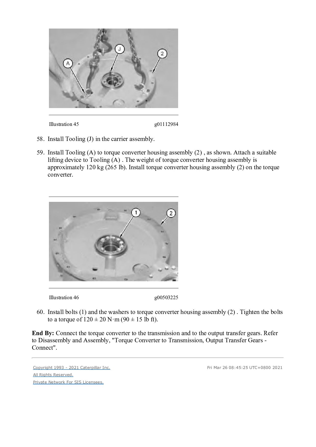
    assembly. 59. Install Tooling (A) to torque converter housing assembly (2) , as shown. Attach a suitable lifting device to Tooling (A) . The weight of torque converter housing assembly is approximately 120 kg (265 lb). Install torque converter housing assembly (2) on the torque converter. Illustration 46 g00503225 60. Install bolts (1) and the washers to torque converter housing assembly (2) . Tighten the bolts to a torque of 120 ± 20 N·m (90 ± 15 lb ft). End By: Connect the torque converter to the transmission and to the output transfer gears. Refer to Disassembly and Assembly, "Torque Converter to Transmission, Output Transfer Gears - Connect". Copyright 1993 - 2021 Caterpillar Inc. All Rights Reserved. Private Network For SIS Licensees. Fri Mar 26 08:45:25 UTC+0800 2021
  22. Shutdown SIS Previous Screen Product: WHEEL LOADER Model: 980H WHEEL

    LOADER A8J Configuration: 980H WHEEL LOADER A8J00001-03999 (MACHINE) POWERED BY C15 ENGINE Disassembly and Assembly 980H Wheel Loader Power Train Media Number -RENR8667-08 Publication Date -01/09/2018 Date Updated -04/09/2018 i02187020 Transmission from Output Transfer Gears - Separate SMCS - 3002-076 Separation Procedure Table 1 Required Tools Tool Part Number Part Description Qty A 1U-9200 Lever Puller Hoist 1 B 138-7575 Link Bracket 1 C 138-7575 Link Bracket 3 Start By: a. Separate the torque converter from the transmission. Refer to Disassembly and Assembly, "Torque Converter from Transmission, Output Transfer Gears - Separate".
  23. Illustration 1 g01105945 Illustration 2 g01105953 1. Use Tooling (A),

    Tooling (B) and a suitable lifting device in order to reposition the transmission and output transfer gears (1) onto suitable cribbing. The weight of the transmission and output transfer gears (1) is approximately 1406 kg (3100 lb). Illustration 3 g01105947
  24. 2. Disconnect harness assemblies (2). Illustration 4 g01105969 3. Remove

    bolts (4) and tube assembly (3). Illustration 5 g01105973 4. Remove O-ring seal (5).
  25. Illustration 6 g01105978 5. Attach Tooling (C) and a suitable

    lifting device to transmission (6). The weight of transmission (6) is approximately 726 kg (1600 lb). Remove bolts (7). Do not remove the two smaller bolts (8). Illustration 7 g01105986 6. Use the suitable lifting device in order to remove transmission (6). Copyright 1993 - 2021 Caterpillar Inc. All Rights Reserved. Private Network For SIS Licensees. Fri Mar 26 08:46:21 UTC+0800 2021
  26. Shutdown SIS Previous Screen Product: WHEEL LOADER Model: 980H WHEEL

    LOADER A8J Configuration: 980H WHEEL LOADER A8J00001-03999 (MACHINE) POWERED BY C15 ENGINE Disassembly and Assembly 980H Wheel Loader Power Train Media Number -RENR8667-08 Publication Date -01/09/2018 Date Updated -04/09/2018 i03416443 Output Transfer Gears - Disassemble SMCS - 3075-015-OJ Disassembly Procedure Table 1 Required Tools Tool Part Number Part Description Qty A 1P-0520 Driver Group 1 B 8B-7548 Push-puller 1 8B-7551 Bearing Puller Assembly 1 9S-9154 Step Plate 1 C 138-7575 Link Bracket 2 D - 3/8" - 16 Forcing Screw 2 Start By: a. Remove the transmission from the output transfer gears. Refer to Disassembly and Assembly, "Transmission from Output Transfer Gears - Separate".
  27. Illustration 1 g01108584 1. Remove speed sensors (1). Illustration 2

    g01108586 2. Remove hose assembly (2). Illustration 3 g01108605 3. Remove bolt (3) and retainer (4) from the input side of the output transfer gear case.
  28. Illustration 4 g01108617 4. Remove O-ring seal (5). Illustration 5

    g01108628 5. Remove yoke (6). Illustration 6 g01108630 6. Remove bolts (7) and the washers from bearing cage (8).
  29. Illustration 7 g01108631 7. Use Tooling (D) in order to

    remove bearing cage (8). Illustration 8 g01108635 8. Use Tooling (A) (not shown) to remove lip seal (9) and outer bearing race (10) from bearing cage (8). Illustration 9 g01108639 9. Remove O-ring seal (11) from bearing cage (8).
  30. Illustration 10 g01108665 10. Remove spacer (12) from transfer shaft

    (12). Illustration 11 g01108680 11. Position the transfer case with the output side upward, as shown. The weight of the output transfer gear group is 525 kg (1160 lb). 12. Mark bolts (14) for installation purposes. Remove bolts (14) and the washers from bearing cage (15). 13. Use Tooling (D) in order to loosen bearing cage (15) from the transfer case. Remove bearing cage (15).
  31. Illustration 12 g01108700 14. Place bearing cage (15) in a

    suitable press, as shown. Press transfer shaft (13) out of bearing cage (15). The weight of transfer shaft (13) is approximately 27 kg (60 lb). Note: Place a suitable block (not shown) under transfer shaft (12) in order to prevent transfer shaft (12) from falling to the ground. Illustration 13 g01108710 15. Use two people to remove bearing cage (15) from output gear (16). The weight of bearing cage (14) is approximately 33 kg (73 lb). Illustration 14 g01108772 16. Remove spacer (17) from output gear (16).
  32. Illustration 15 g01108776 17. Use Tooling (B) to push out

    transfer shaft (13) from bearing (18). Illustration 16 g01108777 18. Remove O-ring seal (21), bolts (19), the washers and retainer (20) from bearing cage (15). Illustration 17 g01108778
  33. Illustration 18 g01108779 19. Use Tooling (A) and a suitable

    press to remove two bearing cones (22) and two bearing cups (23) from bearing cage (15). 20. Remove lip seal (24) from bearing cage (15). Illustration 19 g01771754 21. Mark bolts (25) for installation purposes. Remove nine bolts (25) and the washers. 22. Remove cover assembly (26) with O-ring seal (27).
  34. Illustration 20 g01771954 23. Remove shaft (26A). Illustration 21 g01771836

    24. Remove bolt (26E). Remove the speed sensor and O-ring seal (26D). Remove bolts (26B). Remove cage assembly (26C).
  35. Thank you very much for your reading. Please Click Here.

    Then Get COMPLETE MANUAL. NO WAITING NOTE: If there is no response to click on the link above, please download the PDF document first and then click on it.
  36. Illustration 22 g01771938 25. Remove bolts (26F). Remove cage (26G).

    Illustration 23 g01778734 26. Remove retaining ring (26K). Remove bearing (26H). Remove rotor (26J).
  37. Illustration 24 g01108784 27. Mark the position of input bearing

    cage (28) for installation purposes. Remove bolts (29), the washers and input bearing cage (28). Illustration 25 g01108788 28. Remove shim pack (30). Illustration 26 g01108790 29. Use Tooling (A) (not shown) to remove bearing cup (31) from input bearing cage (28).
  38. Illustration 27 g01108861 30. Remove nuts (32) and the washers.

    Remove cover (33). Illustration 28 g01108865 31. Remove O-ring seal (34). 32. Mark the position of idler bearing cage (35) for installation purposes. Remove bolts (36) and the washers. Illustration 29 g01108871
  39. https://www.aservicemanualpdf.com/ My Dear Friend! Thank you very much for visiting.

    Full manual if required, please enter the following URL into your browser. https://www.aservicemanualpdf.com/