Upgrade to Pro — share decks privately, control downloads, hide ads and more …

Caterpillar_Cat_D6K2_TRACK-TYPE_TRACTOR__Prefix...

dcfv
May 21, 2024
9

 Caterpillar_Cat_D6K2_TRACK-TYPE_TRACTOR__Prefix_EL7__Service_Repair_Manual__EL700001_and_up_.pdf

dcfv

May 21, 2024
Tweet

More Decks by dcfv

Transcript

  1. Shutdown SIS Previous Screen Product: TRACK-TYPE TRACTOR Model: D6K2 TRACK-TYPE

    TRACTOR EL7 Configuration: D6K2 LGP, XL TRACK-TYPE TRACTOR EL700001-UP (MACHINE) POWERED BY C4.4 ENGINE Disassembly and Assembly D6K Track Type Tractor Power Train Media Number -M0066522-04 Publication Date -01/07/2018 Date Updated -25/07/2018 i06830154 Piston Pump (Hydrostatic) - Disassemble SMCS - 3203-015; 4306-015 Disassembly Procedure Table 1 Required Tools Tool Part Number Part Description Qty A 437-3776 Fixture As. 1 1U-9129(1) Adapter Plate 1 1U-5750 Engine Stand 1 B FT-1409 Spacer 4 C 422-5472 Lifting Eye Assembly 2 D 1P-0510 Driver Gp 1 E 136-1452 Retaining Ring Pliers As 1 F 8H-0663 Bearing Puller Gp 1 G 1U-7600 Slide Hammer Puller Gp 1 (1) Part of the Hydraulic Test Bench Tooling. Start By: a. Remove the piston pump. Note: Cleanliness is an important factor. Before the disassembly procedure, clean the exterior of the component.
  2. Illustration 1 g06133100 Illustration 2 g06133092 Personal injury can result

    from being struck by parts propelled by a released spring force. Make sure to wear all necessary protective equipment. Follow the recommended procedure and use all recommended tooling to release the spring force. 1. Use Tooling (B) to secure the piston pump to Tooling (A) or a suitable fixture. 2. Attach Tooling (C) and a suitable lifting device to pump housing (1). Remove bolts (2) and pump housing (1).
  3. Illustration 3 g06133924 3. Remove port plate (3) from pump

    housing (1). Illustration 4 g06133926 4. Remove O-ring seal (5). Use nylon string to remove rotating assembly (4).
  4. Illustration 5 g06133950 5. Remove piston assemblies (6) and retainer

    plate (7) from barrel assembly (8). Illustration 6 g06133954 6. Remove ball joint (9) from barrel assembly (8). Illustration 7 g06134090 7. Remove shim (10) and spring assembly (11) from barrel assembly (8). Illustration 8 g06134094
  5. Illustration 9 g06134096 Personal injury can result from being struck

    by parts propelled by a released spring force. Make sure to wear all necessary protective equipment. Follow the recommended procedure and use all recommended tooling to release the spring force. 8. Use Tooling (D) and a suitable press to compress spring (14). Remove retaining ring (12). 9. Remove washers (13) and spring (14) from barrel assembly (8). Illustration 10 g06134099 Note: Note the orientation of slide (16) for assembly purposes. 10. Remove swashplate assembly (15).
  6. https://www.aservicemanualpdf.com/ My Dear Friend! Thank you very much for visiting.

    Full manual if required, please enter the following URL into your browser. https://www.aservicemanualpdf.com/
  7. Illustration 11 g06134102 11. Remove slide (16) and bearing assemblies

    (17) from swashplate assembly (15). Illustration 12 g06134104 12. Remove bearing liners (18). Illustration 13 g06134105 13. Use Tooling (E) to remove retaining ring (19) from front mounting flange (21). 14. Use Tooling (G) to remove lip seal (20) from front mounting flange (21).
  8. Illustration 14 g06134136 15. Use Tooling (E) to remove retaining

    ring (22) from front mounting flange (21). Illustration 15 g06134179 16. Use a suitable press to remove shaft (23) from front mounting flange (21). Illustration 16 g06134180 17. Remove retaining ring (24). Use Tooling (F) and a suitable press to remove bearing (25) from shaft (23).
  9. Illustration 17 g06134183 Personal injury can result from being struck

    by parts propelled by a released spring force. Make sure to wear all necessary protective equipment. Follow the recommended procedure and use all recommended tooling to release the spring force. 18. Reattach pump housing (1) to Tooling (A) with rear mounting flange assembly (27) facing down. 19. Remove bolts (26). Use a suitable lifting device to remove pump housing (1) from rear mounting flange assembly (27).
  10. Illustration 18 g06134236 20. Remove port plate (28) from pump

    housing (1). Illustration 19 g06134249 21. Remove O-ring seal (30). Use a nylon string to remove rotating assembly (29). Illustration 20 g06134254 22. Remove piston assemblies (31) and retainer plate (32) from barrel assembly (33). Illustration 21 g06134258
  11. 23. Remove ball joint (34) from barrel assembly (33). Illustration

    22 g06134262 24. Remove shim (35) and spring assembly (36) from barrel assembly (33). Illustration 23 g06134265 Illustration 24 g06134268
  12. Personal injury can result from being struck by parts propelled

    by a released spring force. Make sure to wear all necessary protective equipment. Follow the recommended procedure and use all recommended tooling to release the spring force. 25. Use Tooling (D) and a suitable press to compress spring (39). Remove retaining ring (37). 26. Remove washers (38) and spring (39) from barrel assembly (33). Illustration 25 g06134276 Note: Note the orientation of slide (41) for assembly purposes. 27. Remove swashplate assembly (40). Illustration 26 g06134480 28. Remove bearing liners (42).
  13. Illustration 27 g06134580 29. Remove bolts (44) and rear mounting

    flange (43) from rear mounting flange assembly (27). 30. Remove plate (45) and the O-ring seal. Illustration 28 g06134589 31. Remove plate (46) and O-ring seal (48) from rear mounting flange assembly (27). Use Tooling (E) to remove retaining ring (47). Illustration 29 g06134598
  14. 32. Use a suitable press to remove shaft assembly (49)

    from rear mounting flange assembly (27). Illustration 30 g06134633 33. Remove retaining ring (50). Use Tooling (F) and a suitable press to remove bearing (50) from shaft assembly (49). Illustration 31 g06134643 34. Remove plugs (51) and the O-ring seals from pump housing (1). Illustration 32 g06135182
  15. 35. Remove valve assemblies (55). Remove bolts (52), cap (53),

    and O-ring seal (54) from the pump housing. Repeat for the opposite side. Illustration 33 g06134898 36. Remove O-ring seal (56) from valve assembly (55). Repeat for other valves. Illustration 34 g06134900 37. Remove solenoid assemblies (57) from pump housing (1). Illustration 35 g06134903
  16. 38. Remove nuts (58), O-ring seals (59), coil assemblies (60),

    cartridges (61), and O-ring seals (62). Illustration 36 g06134909 Illustration 37 g06134912 39. Remove plugs (63) and the O-ring seals. Remove bolts (65), cover (66), and valve group (64) from the pump housing. Remove gasket (67). Repeat for the opposite side. Illustration 38 g06134925 40. Remove nuts (68), O-ring seals (69), coil assemblies (70), cartridges (71), and O-ring seals (72) from control block (64).
  17. Illustration 39 g06134931 41. Remove bolt (73), retainer (74), and

    eccentric pin (75) from control block (64). Illustration 40 g06134936 42. Remove O-ring seal (76) and spring (77) from eccentric pin (75).
  18. Illustration 41 g06134940 43. Remove levers (78), spring (79), washer

    (80), reaction arm (81), and spool (82) from control block (64). Repeat for opposite side. Illustration 42 g06135001 Illustration 43 g06134994 44. Remove nut (84) and bolts (83) from cover (85). 45. Use a soft faced hammer to tap adjustment screw (86) from the back side of the pump housing until the O-ring seal on cover (85) clears the pump housing. 46. Unscrew cover (86) from adjustment screw (86). Note: Count the number of revolutions required for removal for installation purposes. 47. Remove control piston (86) from pump housing (1). Repeat for opposite side.
  19. Illustration 44 g06135008 48. Remove ring (87) and guide ring

    (88) from pump housing (1). Copyright 1993 - 2021 Caterpillar Inc. All Rights Reserved. Private Network For SIS Licensees. Tue Aug 31 08:13:26 UTC+0800 2021
  20. Shutdown SIS Previous Screen Product: TRACK-TYPE TRACTOR Model: D6K2 TRACK-TYPE

    TRACTOR EL7 Configuration: D6K2 LGP, XL TRACK-TYPE TRACTOR EL700001-UP (MACHINE) POWERED BY C4.4 ENGINE Disassembly and Assembly D6K Track Type Tractor Power Train Media Number -M0066522-04 Publication Date -01/07/2018 Date Updated -25/07/2018 i06830157 Piston Pump (Hydrostatic) - Assemble SMCS - 3203-016; 4306-016 Assembly Procedure Table 1 Required Tools Tool Part Number Part Description Qty A 437-3776 Fixture As. 1 1U-9129(1) Adapter Plate 1 1U-5750 Engine Stand 1 B FT-1409 Spacer 4 C 422-5472 Lifting Eye Assembly 2 D 1P-0510 Driver Gp 1 E 136-1452 Retaining Ring Pliers As 1 F 8H-0663 Bearing Puller Gp 1 G 1U-7600 Slide Hammer Puller Gp 1 H 6V-2055 Grease 1 (1) Part of the Hydraulic Test Bench Tooling. Note: Cleanliness is an important factor. Before assembly, thoroughly clean all parts in cleaning fluid. Allow the parts to air dry. Do not use wiping cloths or rags to dry parts. Lint may be deposited on the parts which may cause trouble. Inspect all parts. If any parts are worn or damaged, use new parts for replacement. Dirt and other contaminants can damage the precision component. Perform assembly procedures on a clean work surface. Always keep components covered and protected .
  21. Note: Check the O-ring seals, the gaskets, and the seals

    for wear or for damage. Replace the components, if necessary. Illustration 1 g06135231 1. Install guide ring (88) and ring (87) into pump housing (1). Repeat for the opposite side. Illustration 2 g06135233 Illustration 3 g06135235 2. Install control piston (87) into pump housing (1).
  22. 3. Install the O-ring seal and cover (85) onto adjustment

    screw (86). Note: Install cover (85) to a depth of 22 revolutions if original depth is unknown. 4. Install bolts (83) onto cover (85). Tighten bolts (83) to a torque of 130 ± 13 N·m (95 ± 10 lb ft). 5. Install nut (84) onto adjustment screw (86). Tighten nut (84) to a torque of 180 ± 18 N·m (133 ± 13 lb ft). Repeat for opposite side. Illustration 4 g06134940 6. Install spool (82), reaction arm (81), washer (80), spring (79), and levers (78) into control block (64). Repeat for opposite side. Illustration 5 g06134936 7. Install spring (77) and O-ring seal (78) onto eccentric pin (75).
  23. Illustration 6 g06134931 8. Install eccentric pin (75), retainer (74),

    and bolt (73) into control block (64). Illustration 7 g06134925 9. Install O-ring seals (72), cartridges (71), coil assemblies (70), O-ring seals (69), and nuts (68) from control block (64).
  24. Illustration 8 g06134912 Illustration 9 g06134909 10. Install gasket (67).

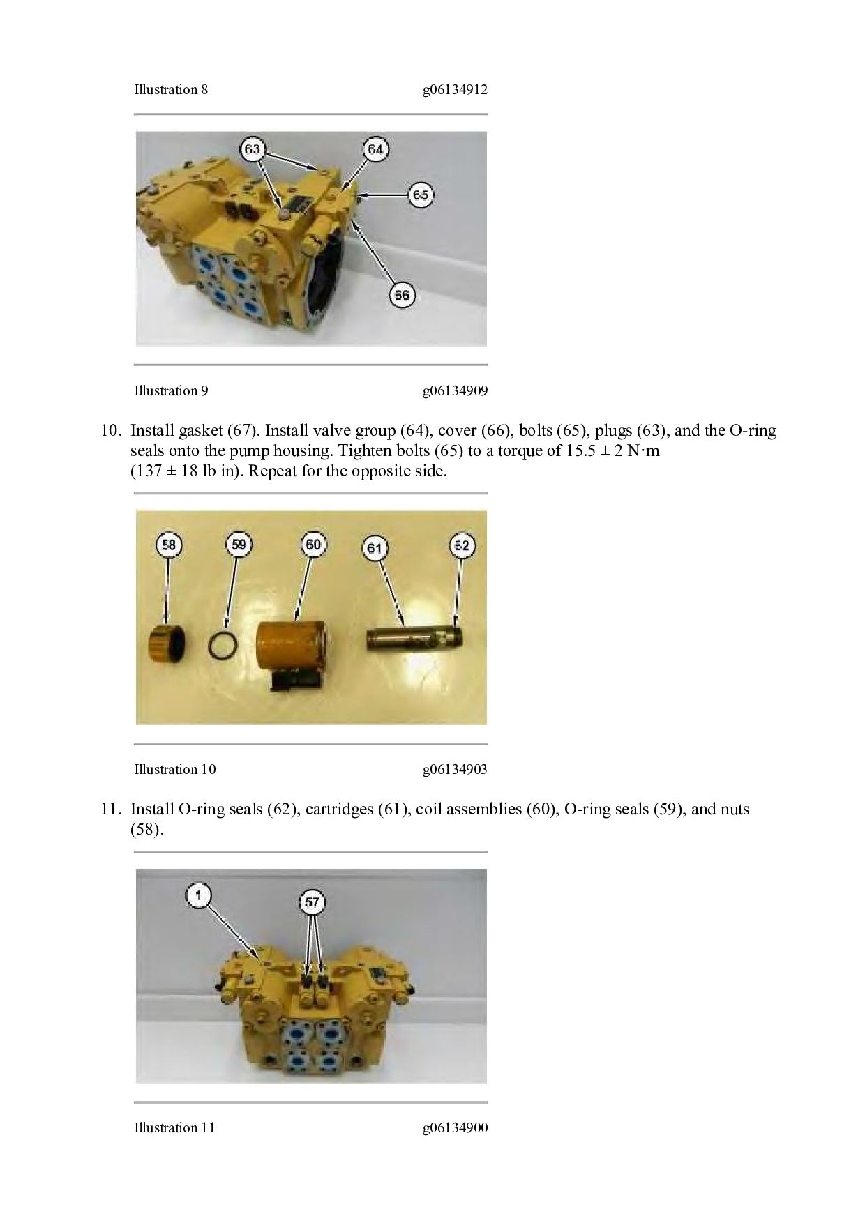
    Install valve group (64), cover (66), bolts (65), plugs (63), and the O-ring seals onto the pump housing. Tighten bolts (65) to a torque of 15.5 ± 2 N·m (137 ± 18 lb in). Repeat for the opposite side. Illustration 10 g06134903 11. Install O-ring seals (62), cartridges (61), coil assemblies (60), O-ring seals (59), and nuts (58). Illustration 11 g06134900
  25. 12. Install solenoid assemblies (57) into pump housing (1). Illustration

    12 g06134898 13. Install O-ring seal (56) onto valve assembly (55). Repeat for other valves. Illustration 13 g06135182 14. Install O-ring seal (54), cap (53), and bolts (52) into the pump housing. Tighten bolts (52) to a torque of 130 ± 13 N·m (96 ± 10 lb ft). Install valves (55). Tighten valves (55) to a torque of 250 N·m (184 lb ft). Repeat for the opposite side. Illustration 14 g06134643
  26. 15. Install plugs (51) and the O-ring seals into pump

    housing (1). Illustration 15 g06135459 Illustration 16 g06135455 16. Use Tooling (F) and a suitable press to install bearing (51) onto shaft assembly (49). Install retaining ring (50) onto shaft assembly (49). Illustration 17 g06136089 17. Use a suitable press to install shaft assembly (49) into rear mounting flange assembly (27). Use Tooling (E) to install retaining ring (47). Install plate (46) and O-ring seal (48) into rear mounting flange assembly (27).
  27. Illustration 18 g06134580 18. Install plate (45) and the O-ring

    seal. 19. Position rear mounting flange (43) onto rear mounting flange (27). Install bolts (44). Illustration 19 g06134480 20. Install bearing liners (42). Illustration 20 g06134276 21. Install swashplate assembly (40). Use Tooling (H) to hold slide (41) in the upright position.
  28. Please write to us. Our email: [email protected] Please go to

    the homepage to get the full manual, or other brand PDF manuals. Home Site: aservicemanualpdf.com
  29. Thank you very much for your reading. Please Click Here.

    Then Get COMPLETE MANUAL. NO WAITING NOTE: If there is no response to click on the link above, please download the PDF document first and then click on it.
  30. Illustration 21 g06134268 Illustration 22 g06134265 Improper assembly of parts

    that are spring loaded can cause bodily injury. To prevent possible injury, follow the established assembly procedure and wear protective equipment. 22. Install spring (39) and washers (38) into barrel assembly (33). 23. Use Tooling (D) and a suitable press to compress spring (39). Install retaining ring (37).
  31. Illustration 23 g06134262 24. Install spring assembly (36) and shim

    (35) into barrel assembly (33). Illustration 24 g06134258 25. Install ball joint (34) onto barrel assembly (33). Illustration 25 g06134254 26. Install retainer plate (32) and piston assemblies (31) onto barrel assembly (33).
  32. Illustration 26 g06135808 27. Attach rear mounting flange (27) to

    Tooling (A). Use a nylon string to install rotating assembly (29). Install O-ring seal (30). Illustration 27 g06134236 28. Use Tooling (H) to hold port plate (28) in place. Install port plate (28) into pump housing (1).
  33. https://www.aservicemanualpdf.com/ My Dear Friend! Thank you very much for visiting.

    Full manual if required, please enter the following URL into your browser. https://www.aservicemanualpdf.com/