Upgrade to Pro — share decks privately, control downloads, hide ads and more …

Caterpillar_Cat_980C_Wheel_Loader__Prefix_63X__Service_Repair_Manual__63X06575_and_up_.pdf

dcfv
May 20, 2024
3

 Caterpillar_Cat_980C_Wheel_Loader__Prefix_63X__Service_Repair_Manual__63X06575_and_up_.pdf

dcfv

May 20, 2024
Tweet

More Decks by dcfv

Transcript

  1. Shutdown SIS Previous Screen Product: WHEEL LOADER Model: 980C WHEEL

    LOADER 63X Configuration: 980C Wheel Loader 63X06575-UP (MACHINE) POWERED BY 3406 Engine Disassembly and Assembly 980C WHEEL LOADER POWER TRAIN Media Number -SENR7757-02 Publication Date -01/04/1984 Date Updated -02/10/2009 SENR77570008 Front Drive Shaft SMCS - 3253-11; 3253-12 Remove Front Drive Shaft 1. Remove four bolts (1) that hold the center drive shaft to the yoke. Pull drive shaft (2) clear of the yoke. 2. Remove six bolts and nuts (3) that hold the bearing cage and retainer to the frame.
  2. 3. Remove bolt (7) and retainer (6). Remove yoke (4)

    from the drive shaft. 4. Remove two bolts (8), and remove retainer (5) from the bearing cage. 5. Remove lip seal (9) from the retainer. 6. Install two 3/8"-16 NC forcing screws (11) in the bearing cage. Remove bearing cage (10) and bearing from the machine. 7. Remove O-ring seal (12) from the bearing cage.
  3. 8. Use tooling (A) and a press to remove the

    bearing from the cage. 9. Remove four bolts and nuts (13) that hold the universal joint to the yoke. 10. Remove front drive shaft (15) from the machine. The weight of the front drive shaft is 29 kg (64 lb.). 11. Remove universal joint (14) from the drive shaft. Install Front Drive Shaft 1. Install universal joint (1) on the front drive shaft. Tighten the bolts to a torque of 135 ± 15 N·m (100 ± 11 lb.ft.). 2. Put front drive shaft (2) in position on the yoke of the front differential. 3. Install the bolts that hold the universal joint to the yoke. Tighten the bolts to a torque of 135 ± 15 N·m (100 ± 11 lb.ft.).
  4. 4. Use tooling (A) and a press to install the

    bearing in the cage. 5. Install O-ring seal (3) on the bearing cage. Put a small amount of 1P808 General Purpose Lubricant on the O-ring seal. 6. Put bearing cage (4) in position in the frame. Make sure the opening (slot) (5) in the bearing cage is toward the top as shown. 7. Install the lip seal in the retainer with tooling (A). Install the seal with the lip toward the front of the retainer. Put a small amount of 1P808 General Purpose Lubricant on the lip of the seal.
  5. 8. Install retainer (7) on the bearing cage. Make sure

    grease fitting (6) is in alignment with the opening (slot) in the bearing cage. 9. Put yoke (9) in position on the drive shaft. 10. Put a small amount of 1P808 General Purpose Lubricant on the O-ring seal. Install seal (8), retainer (10) and the bolt. Tighten the bolt to a torque of 470 ± 50 N·m (347 ± 37 lb.ft.). 11. Install the center drive shaft on the yoke. Tighten the bolts to a torque of 135 ± 15 N·m (100 ± 11 lb.ft.). Remove Center Drive Shaft 1. Remove four bolts (3). Disconnect center drive shaft (2) and universal joint (1) from the yoke.
  6. https://www.aservicemanualpdf.com/ My Dear Friend! Thank you very much for visiting.

    Full manual if required, please enter the following URL into your browser. https://www.aservicemanualpdf.com/
  7. 2. Remove four bolts (4). Remove center drive shaft group

    (2) from the machine. The weight of the center drive shaft group is 32 kg (71 lb.). 3. Remove universal joints (1) and (5) from the center drive shaft group. Install Center Drive Shaft Group 1. Install universal joints (1) on the center drive shaft group. Tighten the bolts to a torque of 135 ± 15 N·m (100 ± 11 lb.ft.). 2. Put center drive shaft group (2) in position on the transfer gear yoke. Install the bolts that hold it. Tighten the bolts to a torque of 135 ± 15 N·m (100 ± 11 lb.ft.). 3. Connect center drive shaft group (2) to the yoke of the front drive shaft. Install the bolts that hold it. Tighten the bolts to a torque of 135 ± 15 N·m (100 ± 11 lb.ft.). Copyright 1993 - 2022 Caterpillar Inc. All Rights Reserved. Private Network For SIS Licensees. Thu Jan 6 02:15:01 UTC+0800 2022
  8. Shutdown SIS Previous Screen Product: WHEEL LOADER Model: 980C WHEEL

    LOADER 63X Configuration: 980C Wheel Loader 63X06575-UP (MACHINE) POWERED BY 3406 Engine Disassembly and Assembly 980C WHEEL LOADER POWER TRAIN Media Number -SENR7757-02 Publication Date -01/04/1984 Date Updated -02/10/2009 SENR77570009 Rear Drive Shaft SMCS - 3253-11; 3253-12 Remove Rear Drive Shaft START BY: a. remove power train guard 1. Remove eight bolts and nuts (1). Remove rear drive shaft (3) from the machine. 2. Remove universal joints (2) from the drive shaft. Install Rear Drive Shaft
  9. 1. Install universal joints (2) on the drive shaft. Tighten

    the bolts to a torque of 135 ± 15 N·m (100 ± 11 lb.ft.). 2. Put rear drive shaft (1) in position between the transfer gears and the rear differential. Install the bolts that hold it. Tighten the bolts to a torque of 135 ± 15 N·m (100 ± 11 lb.ft.). END BY: a. install power train guard Copyright 1993 - 2022 Caterpillar Inc. All Rights Reserved. Private Network For SIS Licensees. Thu Jan 6 02:15:58 UTC+0800 2022
  10. Shutdown SIS Previous Screen Product: WHEEL LOADER Model: 980C WHEEL

    LOADER 63X Configuration: 980C Wheel Loader 63X06575-UP (MACHINE) POWERED BY 3406 Engine Disassembly and Assembly 980C WHEEL LOADER POWER TRAIN Media Number -SENR7757-02 Publication Date -01/04/1984 Date Updated -02/10/2009 SENR77570010 Front Axle Housing SMCS - 3260-11; 3260-12 Remove Front Axle Housing START BY: a. remove front tires and rims b. remove front drive shaft 1. Disconnect hose assembly (1) from the block assembly. 2. Fasten a hoist to each wheel brake assembly as shown.
  11. 3. Remove eight nuts (2) and the washers that hold

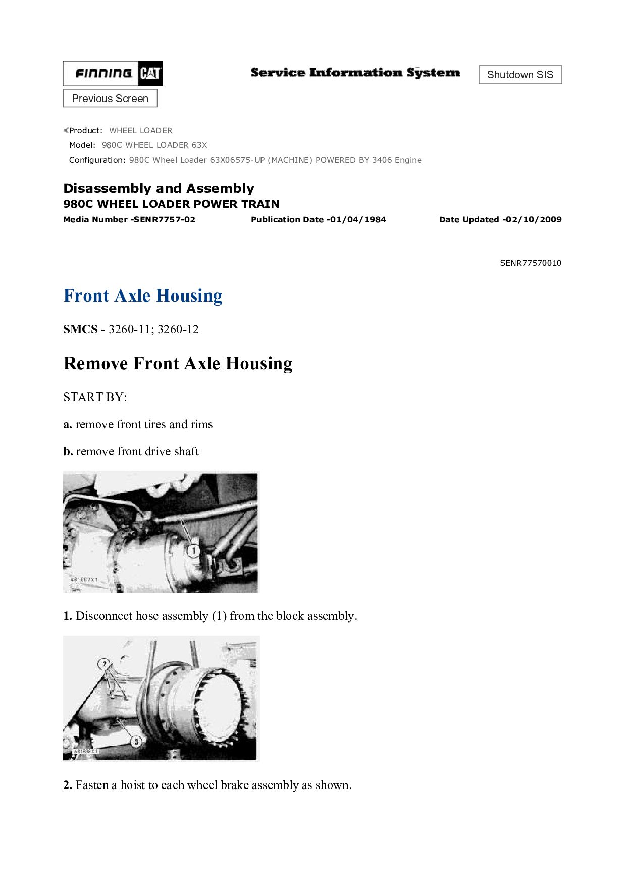
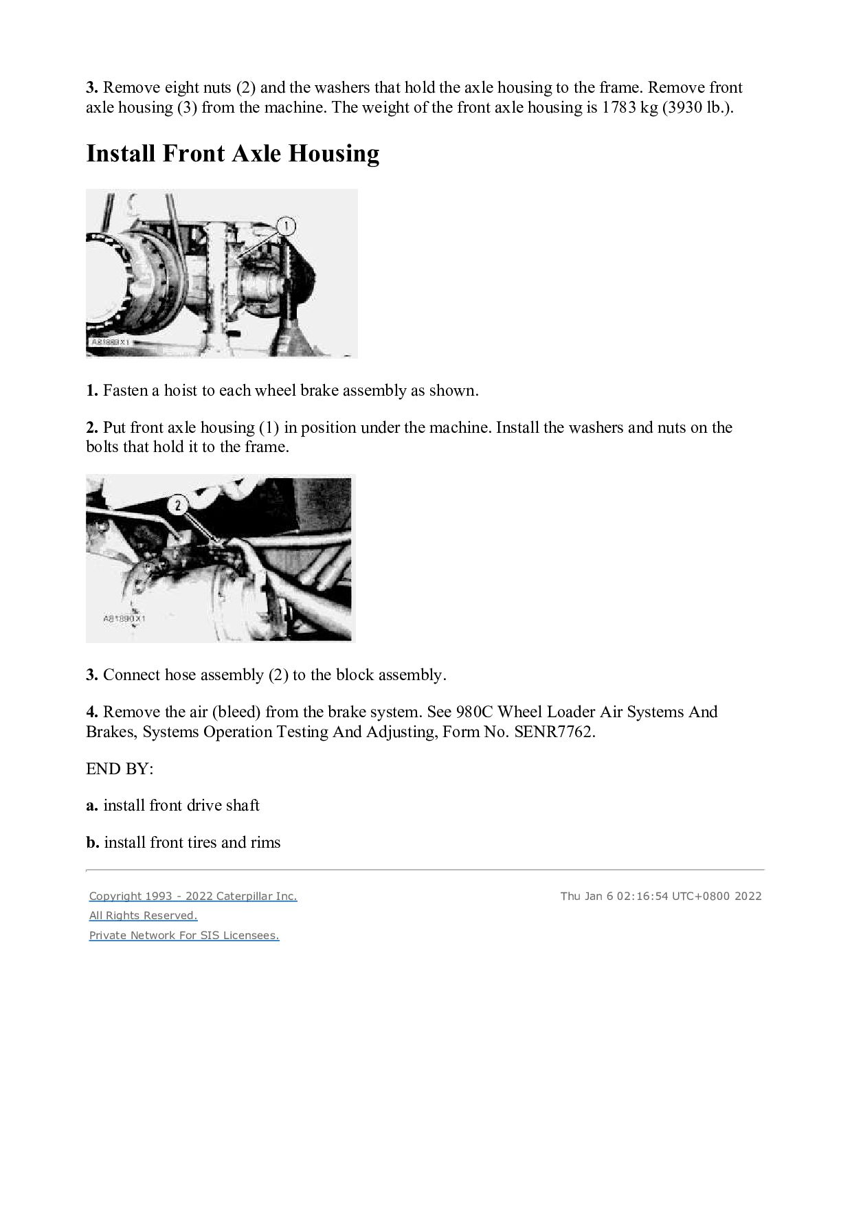
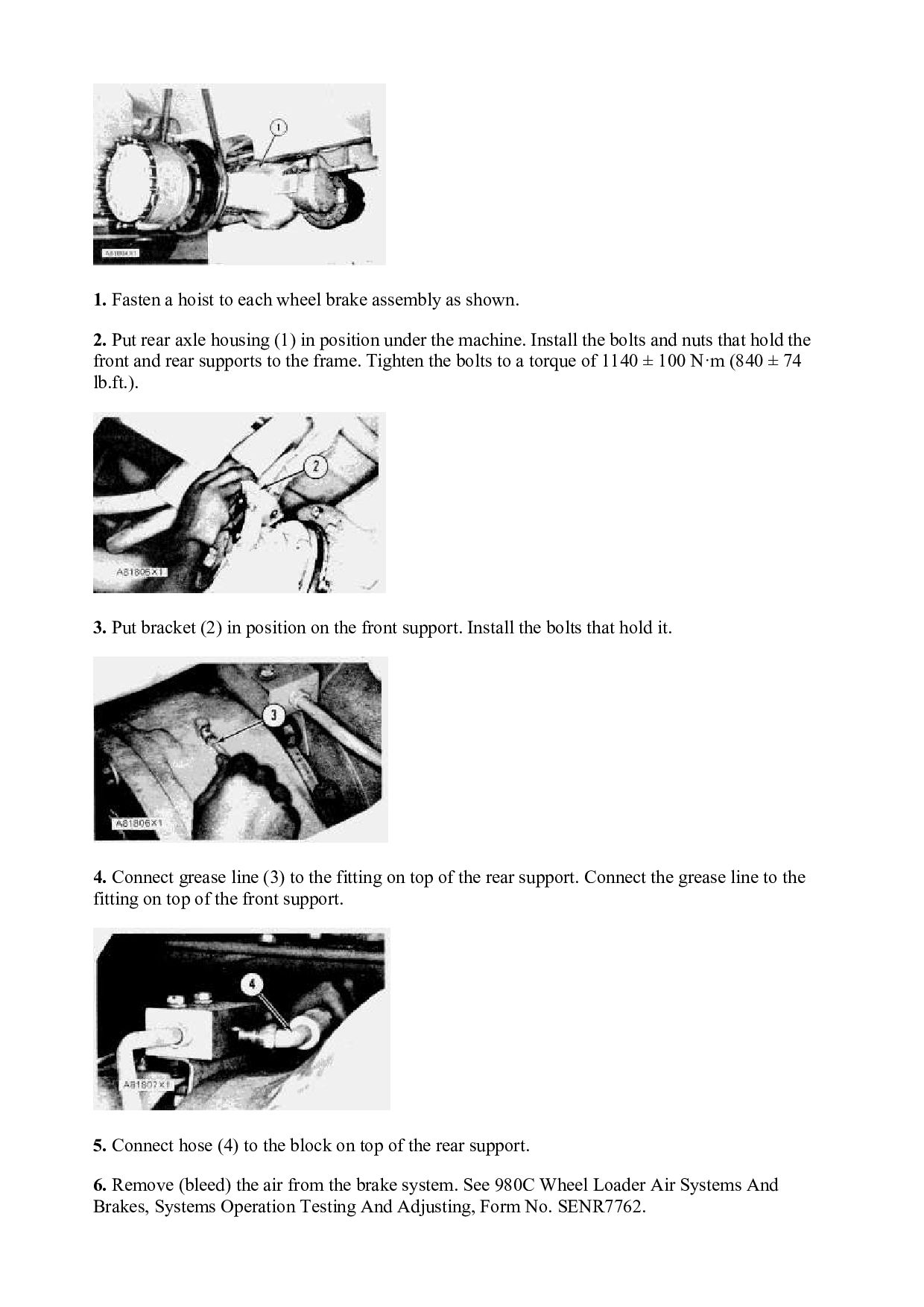
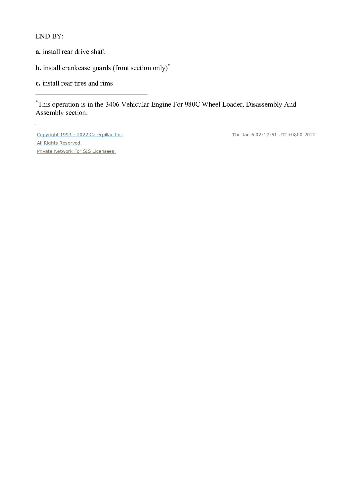
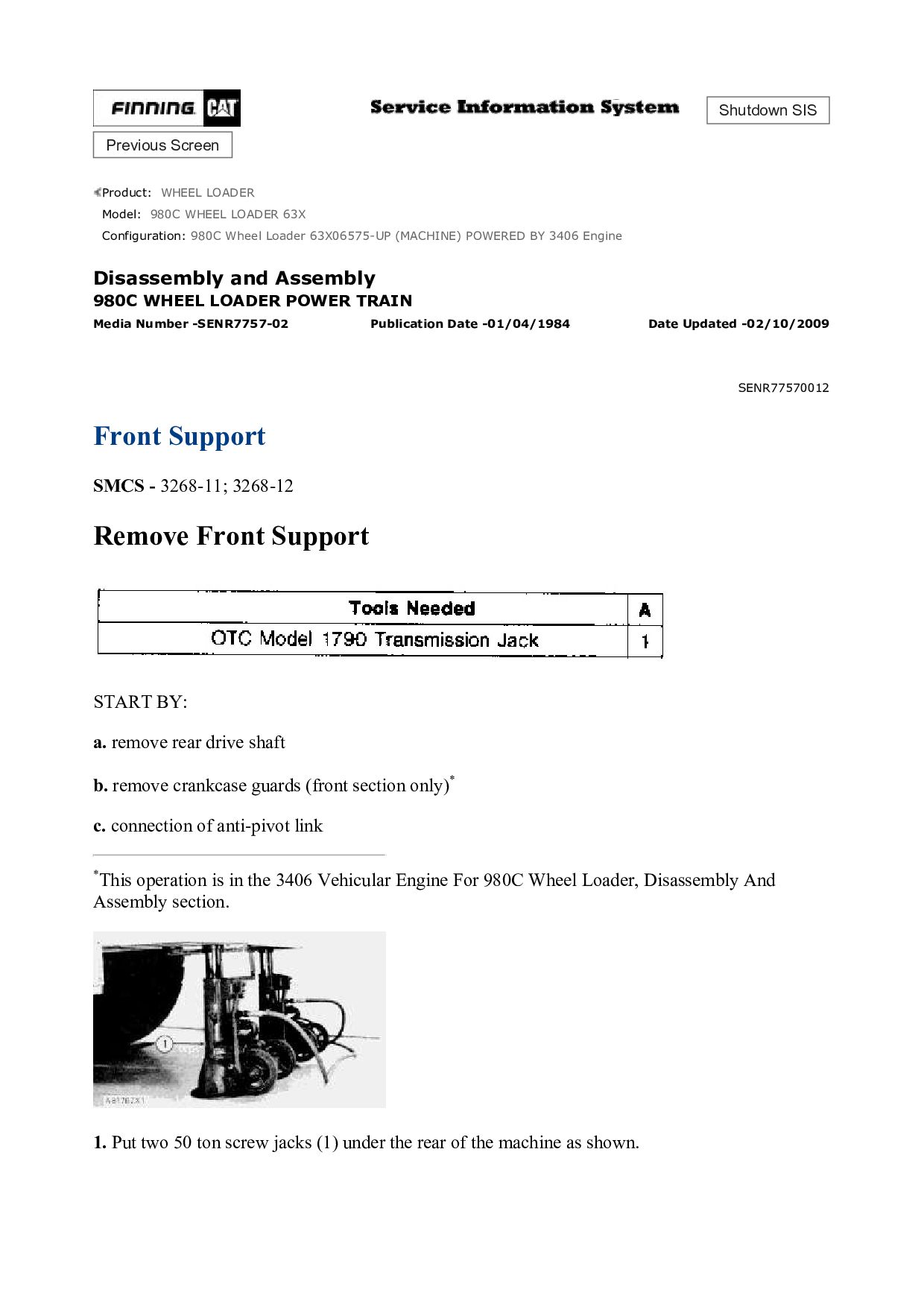
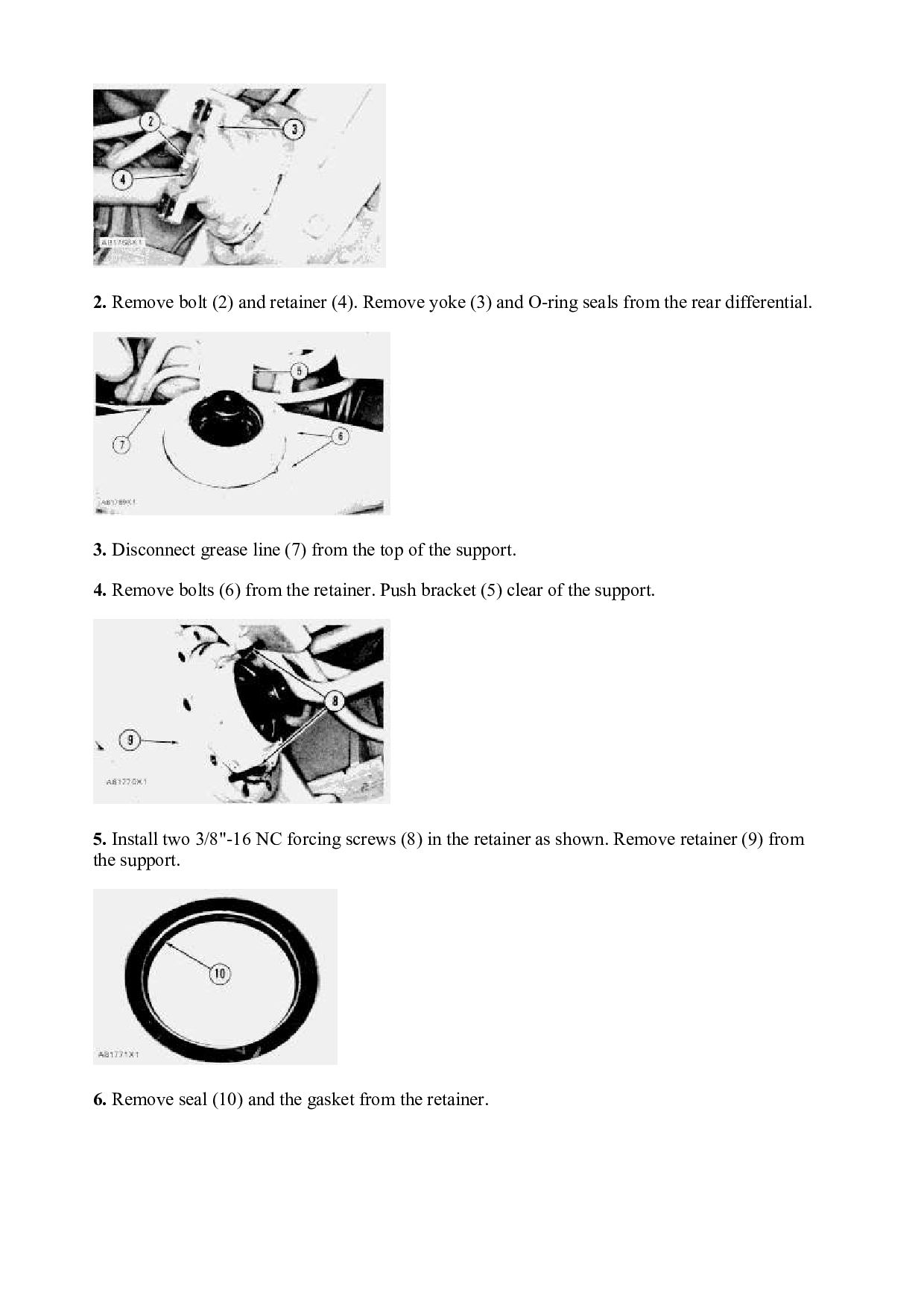
    the axle housing to the frame. Remove front axle housing (3) from the machine. The weight of the front axle housing is 1783 kg (3930 lb.). Install Front Axle Housing 1. Fasten a hoist to each wheel brake assembly as shown. 2. Put front axle housing (1) in position under the machine. Install the washers and nuts on the bolts that hold it to the frame. 3. Connect hose assembly (2) to the block assembly. 4. Remove the air (bleed) from the brake system. See 980C Wheel Loader Air Systems And Brakes, Systems Operation Testing And Adjusting, Form No. SENR7762. END BY: a. install front drive shaft b. install front tires and rims Copyright 1993 - 2022 Caterpillar Inc. All Rights Reserved. Private Network For SIS Licensees. Thu Jan 6 02:16:54 UTC+0800 2022
  12. Shutdown SIS Previous Screen Product: WHEEL LOADER Model: 980C WHEEL

    LOADER 63X Configuration: 980C Wheel Loader 63X06575-UP (MACHINE) POWERED BY 3406 Engine Disassembly and Assembly 980C WHEEL LOADER POWER TRAIN Media Number -SENR7757-02 Publication Date -01/04/1984 Date Updated -02/10/2009 SENR77570011 Rear Axle Housing SMCS - 3260-11; 3260-12 Remove Rear Axle Housing START BY: a. remove rear tires and rims b. remove crankcase guards (front section only)* c. remove rear drive shaft *This operation is in the 3406 Vehicular Engine For 980C Wheel Loader, Disassembly And Assembly section. 1. Disconnect hose (1) from the block on top of the axle housing.
  13. 2. Disconnect grease line (2) from the top of the

    rear support. Disconnect the grease line from the top of the front support. 3. Remove two bolts (3) that hold bracket (4) to the front support. Push the bracket and hoses clear of the support. 4. Fasten a hoist to each wheel brake assembly as shown. 5. Remove eight bolts and nuts (5) that hold the front and rear supports to the frame. Remove rear axle housing (6) from the machine. The weight of the rear axle housing is 1980 kg (4365 lb.). Install Rear Axle Housing
  14. 1. Fasten a hoist to each wheel brake assembly as

    shown. 2. Put rear axle housing (1) in position under the machine. Install the bolts and nuts that hold the front and rear supports to the frame. Tighten the bolts to a torque of 1140 ± 100 N·m (840 ± 74 lb.ft.). 3. Put bracket (2) in position on the front support. Install the bolts that hold it. 4. Connect grease line (3) to the fitting on top of the rear support. Connect the grease line to the fitting on top of the front support. 5. Connect hose (4) to the block on top of the rear support. 6. Remove (bleed) the air from the brake system. See 980C Wheel Loader Air Systems And Brakes, Systems Operation Testing And Adjusting, Form No. SENR7762.
  15. END BY: a. install rear drive shaft b. install crankcase

    guards (front section only)* c. install rear tires and rims *This operation is in the 3406 Vehicular Engine For 980C Wheel Loader, Disassembly And Assembly section. Copyright 1993 - 2022 Caterpillar Inc. All Rights Reserved. Private Network For SIS Licensees. Thu Jan 6 02:17:51 UTC+0800 2022
  16. Shutdown SIS Previous Screen Product: WHEEL LOADER Model: 980C WHEEL

    LOADER 63X Configuration: 980C Wheel Loader 63X06575-UP (MACHINE) POWERED BY 3406 Engine Disassembly and Assembly 980C WHEEL LOADER POWER TRAIN Media Number -SENR7757-02 Publication Date -01/04/1984 Date Updated -02/10/2009 SENR77570012 Front Support SMCS - 3268-11; 3268-12 Remove Front Support START BY: a. remove rear drive shaft b. remove crankcase guards (front section only)* c. connection of anti-pivot link *This operation is in the 3406 Vehicular Engine For 980C Wheel Loader, Disassembly And Assembly section. 1. Put two 50 ton screw jacks (1) under the rear of the machine as shown.
  17. 2. Remove bolt (2) and retainer (4). Remove yoke (3)

    and O-ring seals from the rear differential. 3. Disconnect grease line (7) from the top of the support. 4. Remove bolts (6) from the retainer. Push bracket (5) clear of the support. 5. Install two 3/8"-16 NC forcing screws (8) in the retainer as shown. Remove retainer (9) from the support. 6. Remove seal (10) and the gasket from the retainer.
  18. 7. Remove two bolts, nuts and washers (11) from each

    side of the front support. 8. Loosen the nuts that hold the rear support to the frame approximately 12.7 mm (.50 in.). 9. Fasten tool (A) to the front support as shown. Lift the rear of the machine with the 50 ton screw jacks to a height of approximately 939.8 mm (37 in.). Remove front support (12) from the machine. The weight of the front support is 53 kg (118 lb.). 10. Remove bearing (14) and seal (13) from the support. Install Front Support
  19. 1. Use tool (A) and a press to install the

    bearing in the front support. 2. Install seal (1). Put a small amount of 5P960 Multipurpose Type Grease on the seal. 3. Fasten tooling (B) to the front support as shown. Put 5P960 Multipurpose Type Grease on the trunnion. Put front support (2) in position on the trunnion. Lower the machine with the 50 ton screw jacks until the front support makes contact with the frame. Install the bolts and nuts that hold the front support to the frame. Tighten the bolts to a torque of 1140 ± 100 N·m (840 ± 74 lb.ft.). Tighten the bolts that hold the rear support to a torque of 1140 ± 100 N·m (840 ± 74 lb.ft.). Remove the 50 ton screw jacks from under the machine. 4. Install a new gasket and seal (3) on the retainer. Put a small amount of 5P960 Multipurpose Type Grease on the seal.
  20. 5. Install retainer (5) on the front support. Put bracket

    (4) in position on the retainer. Install the bolts that hold the retainer. 6. Install yoke (6) on the pinion shaft. Install the retainer and bolt that hold it. Tighten the bolt to a torque of 360 ± 45 N·m (265 ± 33 lb.ft.). END BY: a. install crankcase guards (front section only)* b. install rear drive shaft c. separation of anti-pivot link *This operation is in the 3406 Vehicular Engine For 980C Wheel Loader, Disassembly And Assembly section. Copyright 1993 - 2022 Caterpillar Inc. All Rights Reserved. Private Network For SIS Licensees. Thu Jan 6 02:18:48 UTC+0800 2022
  21. Shutdown SIS Previous Screen Product: WHEEL LOADER Model: 980C WHEEL

    LOADER 63X Configuration: 980C Wheel Loader 63X06575-UP (MACHINE) POWERED BY 3406 Engine Disassembly and Assembly 980C WHEEL LOADER POWER TRAIN Media Number -SENR7757-02 Publication Date -01/04/1984 Date Updated -02/10/2009 SENR77570013 Rear Support SMCS - 3268-11; 3268-12 Remove Rear Support START BY: a. remove crankcase guards (front section only)* b. connection of anti-pivot link *This operation is in the 3406 Vehicular Engine For 980C Wheel Loader, Disassembly And Assembly section. 1. Drain the oil from the rear differential. 2. Put two 50 ton screw jacks (1) in position under the rear of the machine as shown.
  22. 3. Remove bolts (2). Remove cover (3) from the support.

    Remove the gasket from the back of the cover. 4. Remove washer (4). Remove bolts (5), and remove plate (6). Remove the washer from behind the plate. 5. Remove bolts and nuts (7) from each side of the rear support. Loosen the bolts and nuts that hold the front support to the frame approximately 12.7 mm (.50 in.). 6. Disconnect grease line (8) from the top of the rear support. 7. Fasten tool (A) to the rear support as shown. Lift the rear of the machine with the two 50 ton screw jacks to a height of approximately 939.8 mm (37 in.). Remove rear support (9) with tool (A).
  23. 8. Remove seal (10) and bearing (11) from the rear

    support. 9. Remove bolts (12) that hold the block to the bracket. 10. Remove all bolts (13) that hold the trunnion to the axle housing except for two that are 180° apart. 11. Remove bracket (14). 12. Fasten tool (A) to the trunnion as shown. Remove the remainder of the bolts that hold the trunnion. Remove trunnion (15) with tool (A). The weight of the trunnion is 34 kg (75 lb.). 13. Remove seal (16) from the trunnion.
  24. Install Rear Support 1. Install seal (1) on the trunnion.

    Put a small amount of clean SAE 90 oil on the seal. 2. Fasten tool (B) to the trunnion. Install trunnion (2) in the axle housing with tool (B). 3. Use tool (A) and a press to install the bearing in the rear support.
  25. 4. Install seal (3) in the rear support. Put a

    small amount of 5P960 Multipurpose Type Grease on the seal. 5. Put 5P960 Multipurpose Type Grease on the trunnion. Fasten tool (B) to the rear support. Install rear support (4) on the trunnion with tool (B). Use the two 50 ton screw jacks to lower the machine until the rear support makes contact with the frame. Install the bolts and nuts that hold the rear support. Tighten the bolts to a torque of 1140 ± 100 N·m (840 ± 74 lb.ft.). Tighten the bolts that hold the front support to a torque of 1140 ± 100 N·m (840 ± 74 lb.ft.). Remove the 50 ton screw jacks. 6. Connect grease line (5) to the top of the rear support. 7. Install washer, plate (6) and washer (7) in the rear support. Tighten the bolts that hold the plate to a torque of 260 ± 25 N·m (190 ± 18 lb.ft.). 8. Install the O-ring seal on the cover for the rear support. Install the cover on the rear support. 9. Fill the rear differential with SAE 90 oil to the correct level. See the Maintenance Guide. END BY: a. install crankcase guards (front section only) * b. separation of anti-pivot link
  26. *This operation is in the 3406 Vehicular Engine For 980C

    Wheel Loader Engine, Disassembly And Assembly section. Copyright 1993 - 2022 Caterpillar Inc. All Rights Reserved. Private Network For SIS Licensees. Thu Jan 6 02:19:45 UTC+0800 2022
  27. Please write to us. Our email: [email protected] Please go to

    the homepage to get the full manual, or other brand PDF manuals. Home Site: aservicemanualpdf.com
  28. Thank you very much for your reading. Please Click Here.

    Then Get COMPLETE MANUAL. NO WAITING NOTE: If there is no response to click on the link above, please download the PDF document first and then click on it.
  29. Shutdown SIS Previous Screen Product: WHEEL LOADER Model: 980C WHEEL

    LOADER 63X Configuration: 980C Wheel Loader 63X06575-UP (MACHINE) POWERED BY 3406 Engine Disassembly and Assembly 980C WHEEL LOADER POWER TRAIN Media Number -SENR7757-02 Publication Date -01/04/1984 Date Updated -02/10/2009 SENR77570014 Front Differential And Bevel Gear SMCS - 3256-11; 3256-12; 3258
  30. a. remove drive axles (front only) b. remove front drive

    shaft 1. Drain the oil from the front axle housing. Connect the anti-pivot link to the main frames of the machine before the machine is lifted. Keep clear of the machine when tooling (A) is installed under the machine, and when the machine is lowered on to tooling (A). 2. Put wood blocks behind the rear wheels. Use the bucket of the machine to lift the front to a height of approximately 1143 mm (45 in.). Install tooling (A) under the front of the machine as shown. 3. Remove brackets (3) and (4) from the axle housing. 4. Remove tube assemblies (1) and (2).
  31. https://www.aservicemanualpdf.com/ My Dear Friend! Thank you very much for visiting.

    Full manual if required, please enter the following URL into your browser. https://www.aservicemanualpdf.com/