Upgrade to Pro — share decks privately, control downloads, hide ads and more …

Caterpillar_Cat_D10R_TRACK-TYPE_TRACTOR__Prefix_3KR__Service_Repair_Manual__3KR00001_and_up_.pdf

dcfv
May 22, 2024
7

 Caterpillar_Cat_D10R_TRACK-TYPE_TRACTOR__Prefix_3KR__Service_Repair_Manual__3KR00001_and_up_.pdf

dcfv

May 22, 2024
Tweet

More Decks by dcfv

Transcript

  1. Shutdown SIS Previous Screen Product: TRACK-TYPE TRACTOR Model: D10R TRACK-TYPE

    TRACTOR 3KR Configuration: D10R Track-Type Tractor 3KR00001-UP (MACHINE) POWERED BY 3412 Engine Disassembly and Assembly D10R TRACK-TYPE TRACTOR POWER TRAIN Media Number -SENR8422-03 Publication Date -01/11/2004 Date Updated -06/12/2017 SENR84220019 Final Drives SMCS - 4050-015; 4050-016; 4050-011; 4050-012 Remove Final Drives Fluid Spillage Containment Care must be taken to ensure that fluids are contained during performance of inspection, maintenance, testing, adjusting and repair of the machine. Be prepared to collect the fluid with suitable containers before opening any compartment or disassembling any component containing fluids. Refer to "TOOLS AND SHOP PRODUCTS GUIDE, NENG2500", for tools and supplies suitable to collect and contain fluids in Caterpillar machines. Dispose fluids according to local regulations and mandates. Start By: a. separation of tracks b. remove axles NOTE: The final drive planetary carriers can be removed in chassis. See Remove Final Drive Planetary Carriers (In Chassis).
  2. Make sure that the short support of Tooling (A) is

    on the bottom, and the long support is on the top when distances (M) and (N) are made. 1. Make an adjustment to bolts (1) on Tooling (A) so distance (M) is 75 mm (2.95 in) and distance (N) is 180 mm (7.08 in). 2. Remove three bolts from the sprocket segments. Fasten a hoist, and install Tooling (A). Make an adjustment to bolts (2) until the bolts are against the final drive hub. 3. Remove bolts (3) that hold the final drive and steering clutch and brake to the frame. NOTICE Do not remove three bolts (4) that hold the steering clutch and brake to the frame.
  3. 4. Remove three bolts (5) that hold the final drive

    and steering clutch and brake together. Typical Example 5. Remove final drive (6) from the machine. The weight of the final drive is approximately 1070 kg (2360 lb). 6. Remove O-ring seal (7) from the steering clutches. Install Final Drives
  4. 1. Inspect all O-ring seals for wear or damage, and

    make replacements if necessary. 2. Put O-ring seal (7) in position on the steering clutches. Typical Example 3. Fasten a hoist, and install Tooling (A) on the final drive. Make an adjustment to Tooling (A), if needed, to put the final drive in a level position. 4. Put the final drive (6) in position on the tractor. 5. Install bolts (3) that hold the final drive in place. Tighten the bolts to a torque of 1125 ± 100 N·m (820 ± 75 lb ft). 6. Install three bolts (5) that hold the final drive to the steering clutch and brake. 7. Remove tool (A) from the final drive. Put clean SAE 30W Oil on the threads of the sprocket segment bolts. Install the bolts and nuts (with the head of the bolts against the final drive). Tighten the nuts to a torque of 870 ± 70 N·m (642 ± 50 lb ft). Tighten the nuts 120 degrees more. Final torque must be a minimum of 1500 N·m (1110 lb ft). End By: a. install axles b. connect track
  5. https://www.aservicemanualpdf.com/ My Dear Friend! Thank you very much for visiting.

    Full manual if required, please enter the following URL into your browser. https://www.aservicemanualpdf.com/
  6. 1. Remove bolts (1) that hold carrier (2) in position

    on the final drive. 2. Install Tooling (A) on the carrier. Fasten a hoist to Tooling (A). 3. Remove carrier (2) from the final drive. The weight of the carrier is approximately 268 kg (590 lb). Remove the O-ring seal from the carrier. 4. Remove bolts (3) and plates (4). 5. Put the carrier assembly in position in a press as shown, and remove shafts (5). 6. Remove gears (6) from the carrier. 7. Remove bearing cones (7) from gears (6).
  7. 8. Install Tooling (B) on gear (6). 9. Remove bearing

    cups (8) with Tooling (B). NOTE: Retainer (10) and spiral ring (9) were removed in the topic, Remove Axles. 10. Put retainer (10) and spiral ring (9) in position on gear (11). NOTE: There is a sun gear in the middle of the planetary carrier that is free to fall if it stays with planetary carrier.
  8. 11. Install Tooling (A) on the retainer. Remove gear (11)

    and the planetary carrier with Tooling (A) and a hoist. The weight of the gear and planetary carrier is approximately 118 kg (260 lb). 12. Remove spiral ring (12) that holds the gear in position. 13. Remove planetary carrier (13) from gear (14). The weight of the planetary carrier is approximately 100 kg (220 lb). 14. Remove bolts (16) and plates (15). 15. Put the planetary carrier in position in a press, and remove four shafts (17) from the carrier.
  9. 16. Remove gears (18) from the planetary carrier. 17. Remove

    bearings (19) from gears (18). 18. Put Tooling (C) in position on the gear assembly as shown. Remove bearing cups (20) from the gear. 19. Remove lockring (21) from gear (18). 20. Remove sun gear (22) from the final drive.
  10. 21. Remove 16 bolts (23) and retainer plate (24) from

    the hub. 22. Put plate (24) in position in a press. Use Tooling (D) and the press to remove the ring. 23. Use a magnet to remove pins (25) from the hub. 24. Put Tooling (A) in position on the hub. Fasten a hoist to Tooling (A), and remove gear (26) and the hub. The weight of the gear and hub is approximately 188 kg (415 lb).
  11. 25. Remove retainer ring (27) from the gear and hub.

    26. Install Tooling (A) on the hub. Fasten a hoist to Tooling (A). Remove hub (28) from gear (26). The weight of the hub is approximately 54 kg (120 lb). 27. Put Tooling (E) in position on the hub as shown. NOTICE Do not lift the hub high enough to make contact with the fittings on the hydraulic cylinder. 28. Use Tooling (E) to remove the sprocket hub and bearing cone (29) from the support hub.
  12. 29. Install tool (F) in hub (30). 30. Fasten a

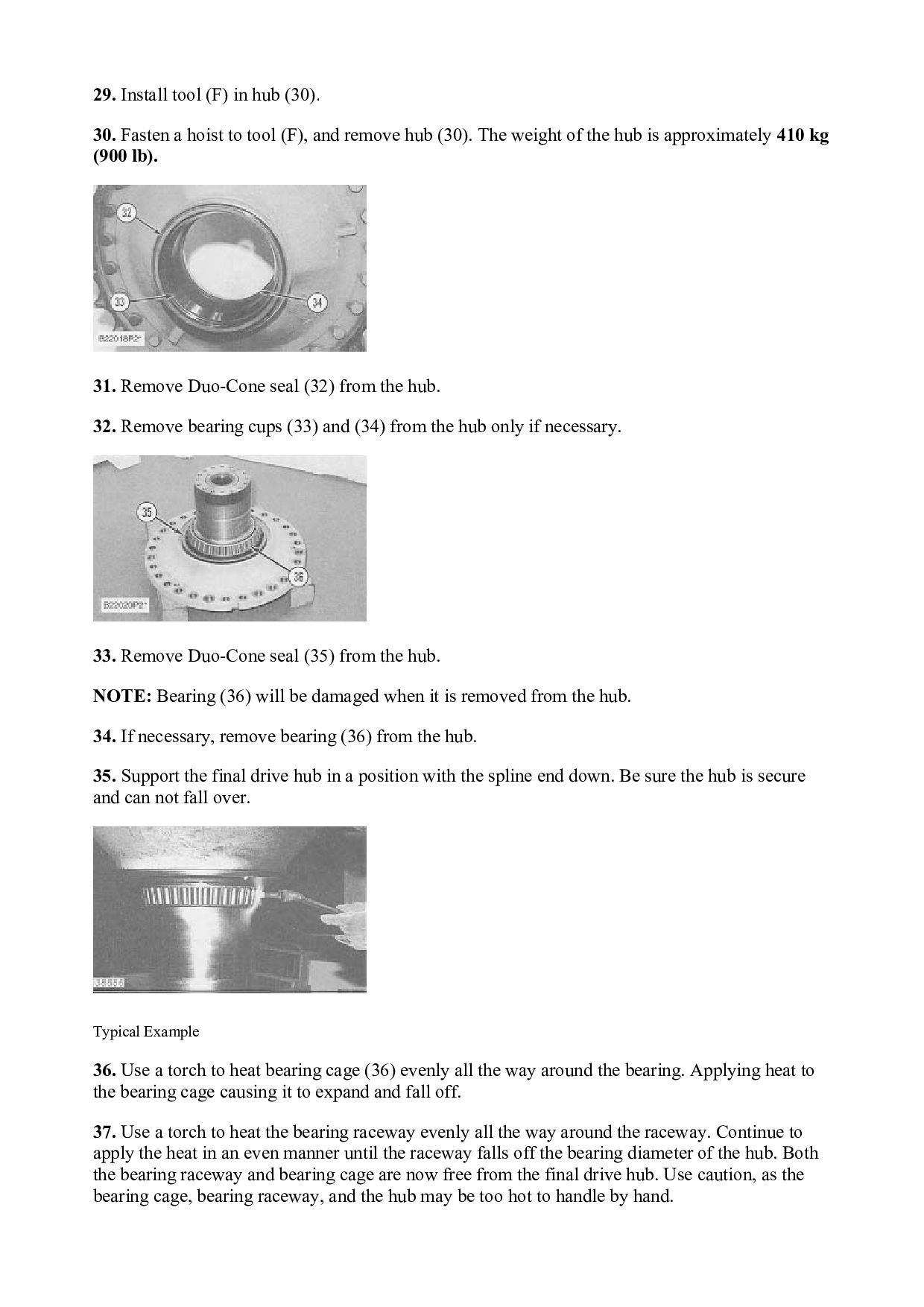
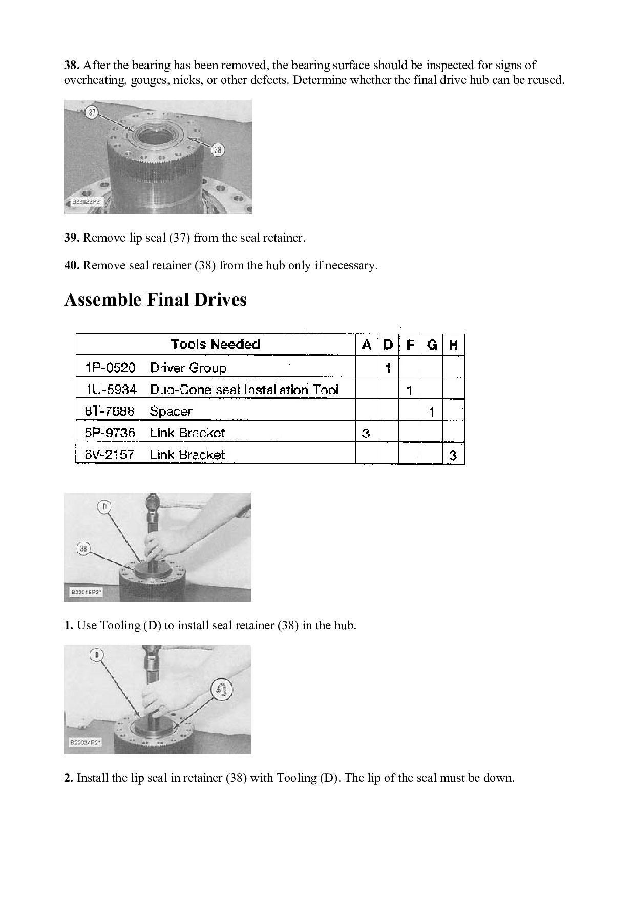
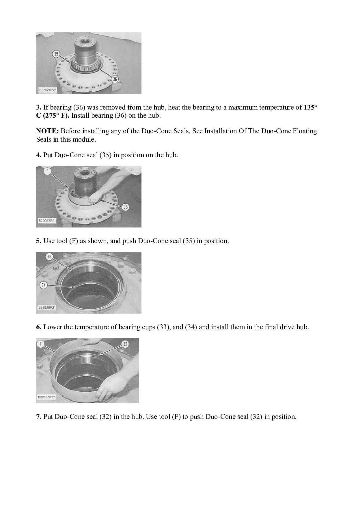
    hoist to tool (F), and remove hub (30). The weight of the hub is approximately 410 kg (900 lb). 31. Remove Duo-Cone seal (32) from the hub. 32. Remove bearing cups (33) and (34) from the hub only if necessary. 33. Remove Duo-Cone seal (35) from the hub. NOTE: Bearing (36) will be damaged when it is removed from the hub. 34. If necessary, remove bearing (36) from the hub. 35. Support the final drive hub in a position with the spline end down. Be sure the hub is secure and can not fall over. Typical Example 36. Use a torch to heat bearing cage (36) evenly all the way around the bearing. Applying heat to the bearing cage causing it to expand and fall off. 37. Use a torch to heat the bearing raceway evenly all the way around the raceway. Continue to apply the heat in an even manner until the raceway falls off the bearing diameter of the hub. Both the bearing raceway and bearing cage are now free from the final drive hub. Use caution, as the bearing cage, bearing raceway, and the hub may be too hot to handle by hand.
  13. 38. After the bearing has been removed, the bearing surface

    should be inspected for signs of overheating, gouges, nicks, or other defects. Determine whether the final drive hub can be reused. 39. Remove lip seal (37) from the seal retainer. 40. Remove seal retainer (38) from the hub only if necessary. Assemble Final Drives 1. Use Tooling (D) to install seal retainer (38) in the hub. 2. Install the lip seal in retainer (38) with Tooling (D). The lip of the seal must be down.
  14. 3. If bearing (36) was removed from the hub, heat

    the bearing to a maximum temperature of 135° C (275° F). Install bearing (36) on the hub. NOTE: Before installing any of the Duo-Cone Seals, See Installation Of The Duo-Cone Floating Seals in this module. 4. Put Duo-Cone seal (35) in position on the hub. 5. Use tool (F) as shown, and push Duo-Cone seal (35) in position. 6. Lower the temperature of bearing cups (33), and (34) and install them in the final drive hub. 7. Put Duo-Cone seal (32) in the hub. Use tool (F) to push Duo-Cone seal (32) in position.
  15. 8. Install tool (H) in final drive hub (30). Fasten

    a hoist to the tool (H). Carefully lower the final drive hub in position. 9. Heat bearing cone (29) to a maximum temperature of 135° C (275° F). 10. Put Tooling (G) in position while the bearing cone is hot. 11. Install retainer plate (24) and bolts (23). Tighten the bolts to put the bearing in its correct position. Tighten the bolts to a torque of 135 ± 15 N·m (100 ± 11 lb ft). 12. Leave the plate and bolts in place until the bearing has become cool. 13. Install Tooling (A) on hub (28). Fasten a hoist to Tooling (A). 14. Lower hub (28) in position in gear (26).
  16. 15. Install retainer ring (27) in the groove in the

    gear. 16. Install Tooling (A) on the inside of the hub. Fasten a hoist to Tooling (A). Lower the hub and gear (26) in position in the final drive hub. 17. Put pins (25) in position in the hub. 18. Use a straight edge, such as the 7H-1941 Base from the 8S-2328 Dial Indicator Test Group, to make sure pins (25) and hub (28) are below the surface of hub (39). The pins must be 0 to .127 mm (0 to .005 in) below the surface level of hub (39). None of the pins may protrude above the hub surface.
  17. 19. Use a press and Tooling (D) to install ring

    (40) in retainer plate (24). 20. Put retainer plate (24) in position. Install bolts (23) that hold the plate to the hub. Tighten the bolts to a torque of 135 ± 15 N·m (100 ± 11 lb ft). NOTE: There must be metal to metal contact between retainer plate (24) and hub (39). 21. Install retainer ring (21) in gear (18). 22. Install bearing cups (20) in the gear with Tooling (D) and a press until the bearings make contact with the retainer ring.
  18. 23. Put bearing cones (41) in position in gear. 24.

    Put gears (18) and the bearing cones in position in carrier (13). 25. Lower the temperature of shafts (17), and install them in the carrier and gears. Use a press if necessary. Install shafts (17) until the small end of the shaft extends 0.08 ± 0.05 mm (.003 ± .002 in) past the surface of the carrier. This is to make sure that there is no metal contact between shafts (17) and the plates when they are installed. 26. Install four plates (15) and bolts (16). Tighten the bolts to a torque of 55 ± 7 N·m (41 ± 5 lb ft). NOTE: There must be metal to metal contact between shafts (17) and plates (15). Use a feeler gauge to make sure there is a gap of 0.08 ± 0.05 mm (.003 ± .002 in) between plates (15) and the surface of the carrier. 27. After four plates (15) have been installed, use a press to push the plates even with the surface of the carrier.
  19. 28. Fasten a hoist to carrier assembly (13). Lower the

    carrier assembly onto gear (14). 29. Put spiral ring (12) in position in the groove in the gear. 30. Put sun gear (14) in position in the planetary carrier. Use a wire (42) to hold the gear in place when the planetary carrier is installed in the final drive. Install the wire across the bottom of the gear from the outside of the planetary carrier as shown. 31. Put retainer (10) and spiral ring (9) in position in gear (11). 32. Install one of tool (A) on the gear. Fasten a hoist to tool (A). 33. Align the gears in the planetary carrier with the gear in the hub. Lower the planetary carrier in the final drive. Remove the wire that holds the sun gear in place when the planetary carrier is within 12.7 mm (.50 in) of the original position in the final drive. 34. Use tool (D) and a press to install the bearing races in gear (6).
  20. 35. Put two bearings (7) in position in gear (6).

    36. Put gears (6) in position in carrier (2). 37. Lower the temperature of shafts (17). Install the shafts in carrier (2) and the gears. If necessary, use a press to install the shafts. Install the shafts until the small end of the shaft extends 0.08 ± 0.05 mm (.003 ± .002 in) past the surface of the carrier. This is to make sure that there is a metal to metal contact between shafts (17) and the plates when they are installed. 38. Put O-ring seals (43) in position in plates (4). 39. Install plates (4) and bolts (3). Tighten the bolts to a torque of 135 ± 15 N·m (100 ± 11 lb ft). NOTE: There must be metal to metal contact between shafts (17) and plates (4). Use a feeler gauge to make sure there is a gap of 0.08 ± 0.05 mm (.003 ± .002 in) between plates (4) and the surface of the carrier.
  21. 40. After four plates (4) have been installed, use a

    press to push the plates even with the surface of the carrier. 41. Put O-ring seal (44) in position on carrier (2). 42. Install Tooling (A) on carrier (2). Fasten a hoist to Tooling (A). 43. Lower carrier (2) in position in the final drive. Make an alignment of the drain hole in the carrier with O-ring seal (45) in the final drive hub. 44. Install bolts (1) that hold the carrier in place. End By: a. install final drives Copyright 1993 - 2021 Caterpillar Inc. All Rights Reserved. Private Network For SIS Licensees. Thu Nov 18 20:15:08 UTC+0800 2021
  22. Shutdown SIS Previous Screen Product: TRACK-TYPE TRACTOR Model: D10R TRACK-TYPE

    TRACTOR 3KR Configuration: D10R Track-Type Tractor 3KR00001-UP (MACHINE) POWERED BY 3412 Engine Disassembly and Assembly D10R TRACK-TYPE TRACTOR POWER TRAIN Media Number -SENR8422-03 Publication Date -01/11/2004 Date Updated -06/12/2017 SENR84220020 Steering Clutches & Brakes SMCS - 4100-011; 4100-012 Remove Steering Clutches & Brakes Fluid Spillage Containment Care must be taken to ensure that fluids are contained during performance of inspection, maintenance, testing, adjusting and repair of the machine. Be prepared to collect the fluid with suitable containers before opening any compartment or disassembling any component containing fluids. Refer to "TOOLS AND SHOP PRODUCTS GUIDE, NENG2500", for tools and supplies suitable to collect and contain fluids in Caterpillar machines. Dispose fluids according to local regulations and mandates. Start By: a. separation of tracks b. remove axles
  23. Make sure the short support of Tooling (A) in on

    the bottom and the long support is on the top when distances (M) and (N) are made. 1. Make an adjustment to bolts (1) on Tooling (A) so the distance (M) is 143 mm (5.63 in) and distance (N) is 104 mm (4.09 in). 2. Remove three bolts from the sprocket segments. Fasten a hoist, and install Tooling (A). Make an adjustment to bolts (2) until the bolts are against the final drive hub. 3. Remove bolts (3) that hold the final drive and steering clutch and brake to the frame. 4. Remove bolts (4) that hold the steering clutch and brake to the frame.
  24. Do not remove bolts (5) that hold the final drive

    to the steering clutch and brake. If the bolts are removed, it is possible for the units to separate during removal. Typical Example 5. Remove the final drive and steering clutch and brake (6) as a unit. The weight of the unit is approximately 1460 kg (3220 lb). Remove the O-ring seal from the steering clutch and brake housing. Install Steering Clutches & Brakes Typical Example 1. Inspect all O-ring seals for wear or damage, and make replacements if necessary. 2. Place the O-ring seal in position on the rear of the steering clutch and brake housing.
  25. 3. Fasten a hoist, and install Tooling (A) on the

    final drive. Make an adjustment to Tooling (A), if needed, to put the final drive and steering clutch and brake in a level position. 4. Put final drive and steering clutch and brake (6) in position on the machine. 5. Install bolts (3) that hold the final drive in place. Tighten the bolts to a torque of 1125 ± 100 N·m (820 ± 75 lb ft). 6. Install three bolts (4) that hold the steering clutch and brake to the frame. 7. Loosen bolts (2), and remove Tooling (A) from the final drive. Put clean SAE 30W Oil or an equivalent lubricant on the threads of the sprocket segment bolts. Install the bolts and nuts (with the head of the bolts against the final drive). Tighten the nuts to a torque of 340 ± 68 N·m (250 ± 50 lb ft). Tighten the nuts 120 degrees more. Final torque must be a minimum of 884 N·m (650 lb ft). End By: a. connection of tracks b. install axles Copyright 1993 - 2021 Caterpillar Inc. All Rights Reserved. Private Network For SIS Licensees. Thu Nov 18 20:16:07 UTC+0800 2021
  26. Shutdown SIS Previous Screen Product: TRACK-TYPE TRACTOR Model: D10R TRACK-TYPE

    TRACTOR 3KR Configuration: D10R Track-Type Tractor 3KR00001-UP (MACHINE) POWERED BY 3412 Engine Disassembly and Assembly D10R TRACK-TYPE TRACTOR POWER TRAIN Media Number -SENR8422-03 Publication Date -01/11/2004 Date Updated -06/12/2017 SENR84220021 Final Drives & Steering Clutches & Brakes SMCS - 4050; 4100-015; 4100-016; 4100-029 Separation & Connection Of Final Drives & Steering Clutches & Brakes Fluid Spillage Containment Care must be taken to ensure that fluids are contained during performance of inspection, maintenance, testing, adjusting and repair of the machine. Be prepared to collect the fluid with suitable containers before opening any compartment or disassembling any component containing fluids. Refer to "TOOLS AND SHOP PRODUCTS GUIDE, NENG2500", for tools and supplies suitable to collect and contain fluids in Caterpillar machines. Dispose fluids according to local regulations and mandates. Start By: a. remove final drives and steering clutches and brakes 1. Remove O-ring seal (1) from the face of the steering clutch and brake and O-ring seals (2).
  27. 2. Install Tooling (A) on the steering clutch and brake

    as shown, and fasten a hoist. 3. Remove three bolts (5) that hold steering clutch and brake (3) to final drive (4). Remove steering clutch and brake (3) from final drive (4). The weight of the steering clutch and brake is approximately 388 kg (855 lb). 4. Turn the steering clutch and brake (3) over. Remove O-ring seal (6). NOTE: The following steps are for the connection of the final drives and steering clutches and brakes. 5. Inspect the O-ring seals for damage, and make replacements if needed. Put clean oil on the O- ring seals. 6. Put O-ring seal (6) in position on steering clutch and brake (3). 7. Install Tooling (A) on the steering clutch and brake, and fasten a hoist. Put steering clutch and brake (3) in position on final drive (4). 8. Install three bolts (5) that hold the steering clutch and brake to final drive. 9. Install O-ring seals (1) and (2) on the face of the steering clutch and brake. End By: a. install final drives and steering clutches and brakes
  28. Disassemble Steering Clutches and Brakes Start By: a. separation of

    final drive and steering clutch and brake 1. Remove O-ring seal (1). 2. Remove four bolts (2) and retainer ring (3). The brake group contains springs that are under compression. To prevent possible personal injury from flying parts, the brake group must be disassembled exactly as the following steps describe. Do not remove bolts (12) until after bolts (6) are slowly loosened and removed.
  29. 3. Install tool (A) to brake group (4) as shown.

    Separate brake group (4) from steering clutch group (5). The weight is 272 kg (600 lb). Bolts (12) and (6) hold a spring under compression. To prevent possible personal injury from flying parts, bolts (6) must be removed before bolts (12). 4. Loosen bolts (6) slowly and evenly to partially release the spring tension in the brake group (4). 5. After the spring tension has been released, remove bolts (6) and retaining plate (7) from the housing. 6. Remove plates (9) and discs (8) from brake housing (10). 7. Remove bearing race (11).
  30. 8. Rotate brake housing (10) over. 9. Loosen bolts (12)

    slowly and evenly until the spring tension is completely released. 10. Install tool (A) as shown to brake housing (10) and remove brake housing (10) from the retainer. 11. Remove bearing (14) from brake housing (10). 12. Remove O-ring seals (15) from brake housing (10). 13. Remove ring (13) from brake housing (10). 14. Remove spool (16) from brake housing (10). 15. Be aware of the spring position before removal for assembly purposes. 16. Remove four springs (17) from piston assembly (18).
  31. Thank you very much for your reading. Please Click Here.

    Then Get COMPLETE MANUAL. NO WAITING NOTE: If there is no response to click on the link above, please download the PDF document first and then click on it.
  32. 17. Remove piston (19) from retainer (20). Remove ring (21)

    using tool (C) from piston (19). 18. Remove the seal ring from piston (19) and retainer (20). 19. Remove three seal rings (23) from shaft assembly (22). 20. Remove bearing (24). 21. Rotate steering clutch group over. 22. Remove four bolts (25) from hub (26). 23. Install tool (E) to hub (26) as shown and remove hub (26).
  33. 24. Remove bolts (27) and remove retaining plate (28). 25.

    Remove seven plates (30) and eight discs (29) from steering hub (31). 26. Remove snap ring (32) using tool (B). 27. Remove bearing (34) and plate (33).
  34. 28. Install two 3/8 1P-7405 - 16 Eyebolts in piston

    (35) and remove piston (35) from hub (31). 29. Remove seal ring (36) from piston (35). 30. Remove seal ring (39) from plate (37). 31. Remove ring (38) using tool (C) and remove plate (37). 32. Install tool (A) to hub (31) as shown and remove hub (31) from shaft assembly (22). Assemble Steering Clutches & Brakes
  35. https://www.aservicemanualpdf.com/ My Dear Friend! Thank you very much for visiting.

    Full manual if required, please enter the following URL into your browser. https://www.aservicemanualpdf.com/