Upgrade to Pro — share decks privately, control downloads, hide ads and more …

Caterpillar_Cat_D10_TRACK-TYPE_TRACTOR__Prefix_84W__Service_Repair_Manual__84W00001-00645_.pdf

dcfv
May 22, 2024
3

 Caterpillar_Cat_D10_TRACK-TYPE_TRACTOR__Prefix_84W__Service_Repair_Manual__84W00001-00645_.pdf

dcfv

May 22, 2024
Tweet

More Decks by dcfv

Transcript

  1. Shutdown SIS Previous Screen Product: TRACK-TYPE TRACTOR Model: D10 TRACK-TYPE

    TRACTOR 84W Configuration: D10 TRACTOR 84W00001-00645 (MACHINE) POWERED BY D348 ENGINE Disassembly and Assembly D10 TRACTOR POWER TRAIN Media Number -SENR7491-02 Publication Date -01/07/1981 Date Updated -15/07/2005 SENR74910016 Final Drive SMCS - 4050-12; 4050-15; 4050-16; 4050-11 Remove Final Drive
  2. start by: a) separation of track NOTE: The final drive

    planet carriers, hub and ring gear can be removed in chassis. See REMOVE FINAL DRIVE PLANET CARRIERS, HUB AND RING GEAR (in chassis). 1. Turn the final drive until drain plug (1) is on the bottom as shown. Remove drain plug (1) and drain the oil from the final drive. 2. Remove three bolts (2) from the center of cover (4). Remove four bolts (3) and cover (4) from the final drive. Remove the O-ring seal from the cover.
  3. 3. Remove spiral lockring (5), ring (6) and retainer (7).

    Remove O-ring seal (8) from retainer (7). 4. Install tool (A) and fasten a hoist as shown. Remove the outer axle. The weight of the outer axle is 85 lb. (39 kg). Make sure that the short support of tooling (B) is on bottom and the long support is on the top when distances (M) and (N) are made. 5. Make an adjustment to bolts (9) on tooling (B) so distance (M) is 5 in. (12.70 cm) and distance (N) is 5.5 in. (13.97 cm).
  4. 6. Remove two bolts from the sprocket segments. Fasten a

    hoist and install tooling (B). Make an adjustment to bolts (13) until the bolts are against the final drive hub. 7. Remove thirty-three one inch diameter bolts (10) that hold the final drive, steering clutch, and brake and spacer to the frame. 8. Remove three 5/8" bolts (14) that hold the steering clutch and brake to the final drive and spacer. Do not remove the three 5/8 in. diameter bolts (11). Bolts (11) hold the steering clutch and brake to the frame. 9. Remove final drive (12) from the frame. The weight is 4450 lb. (2003 kg). NOTICE Make sure the final drive is level when it is removed to prevent damage to the bladder. Remove tooling (B) from the final drive before the hoist is disconnected from tooling (B). Install Final Drive
  5. https://www.aservicemanualpdf.com/ My Dear Friend! Thank you very much for visiting.

    Full manual if required, please enter the following URL into your browser. https://www.aservicemanualpdf.com/
  6. 1. Inspect all O-ring seals for damage and make replacements

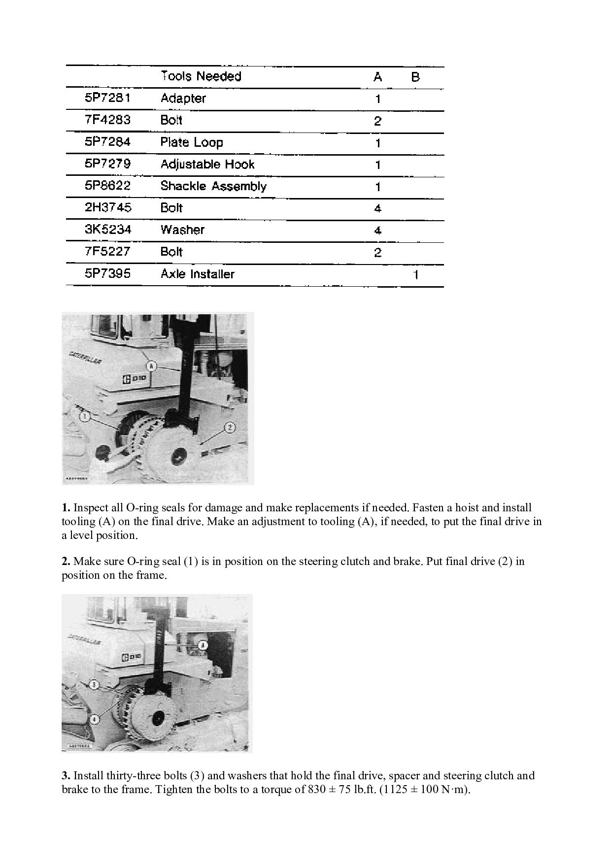
    if needed. Fasten a hoist and install tooling (A) on the final drive. Make an adjustment to tooling (A), if needed, to put the final drive in a level position. 2. Make sure O-ring seal (1) is in position on the steering clutch and brake. Put final drive (2) in position on the frame. 3. Install thirty-three bolts (3) and washers that hold the final drive, spacer and steering clutch and brake to the frame. Tighten the bolts to a torque of 830 ± 75 lb.ft. (1125 ± 100 N·m).
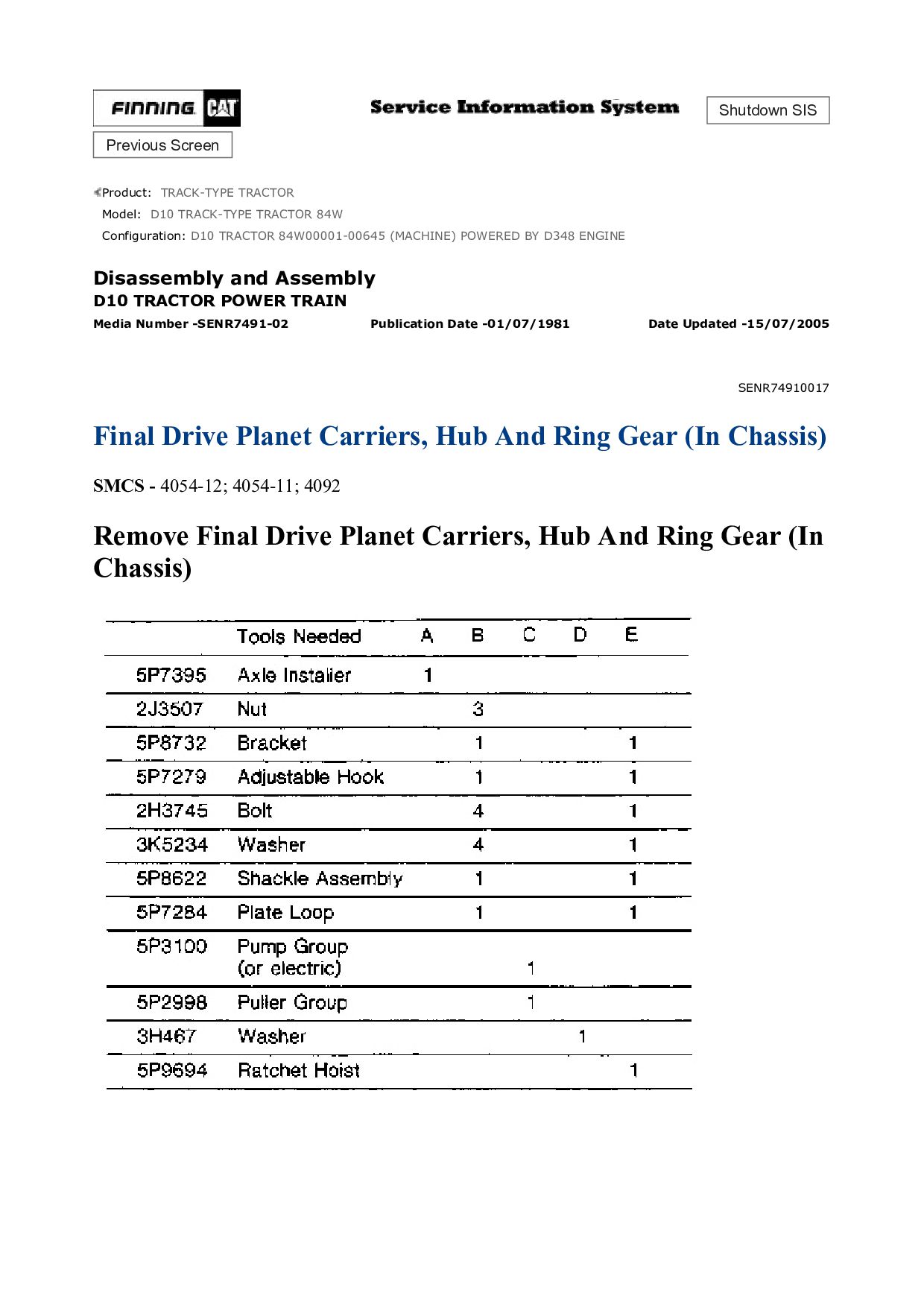
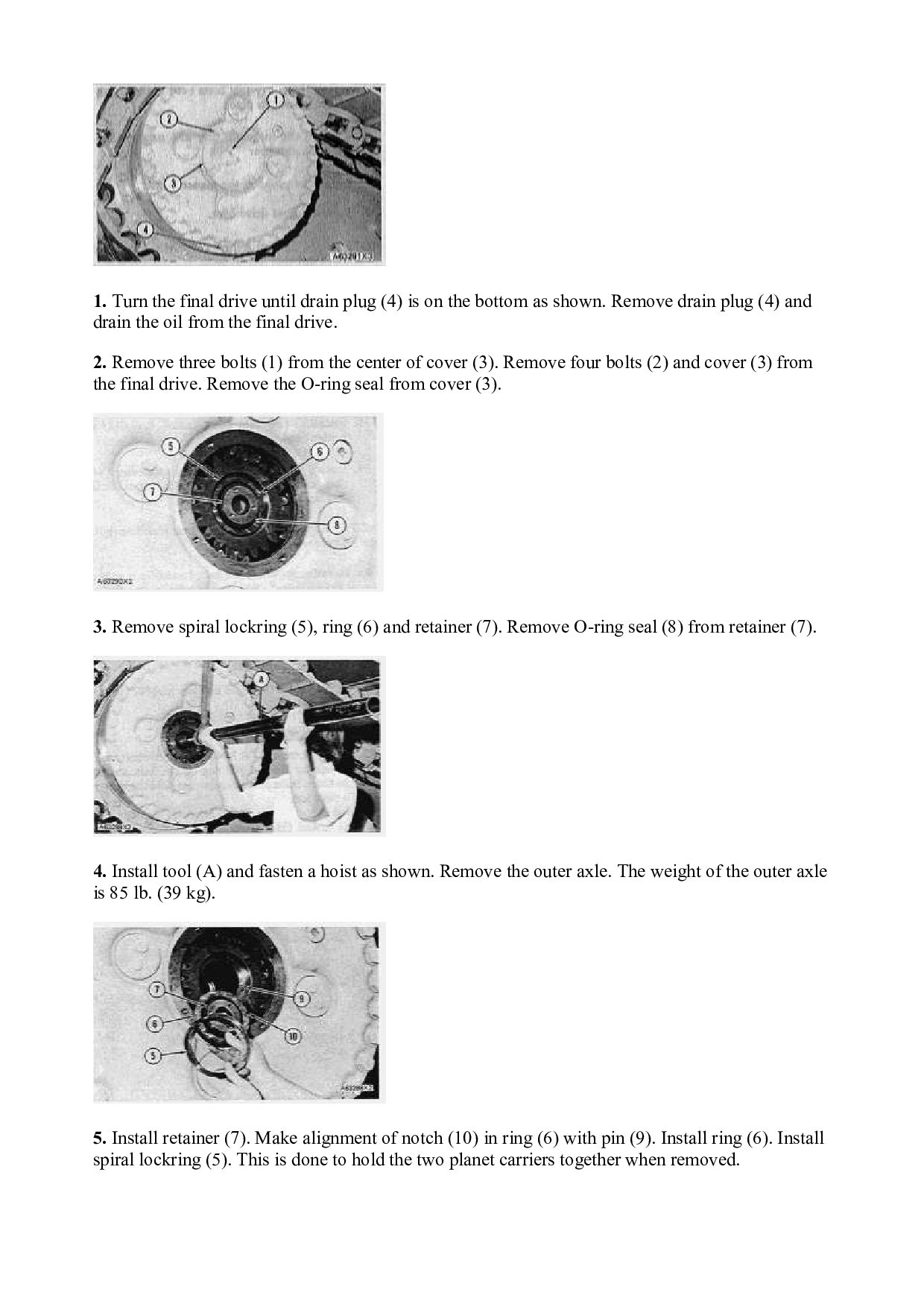
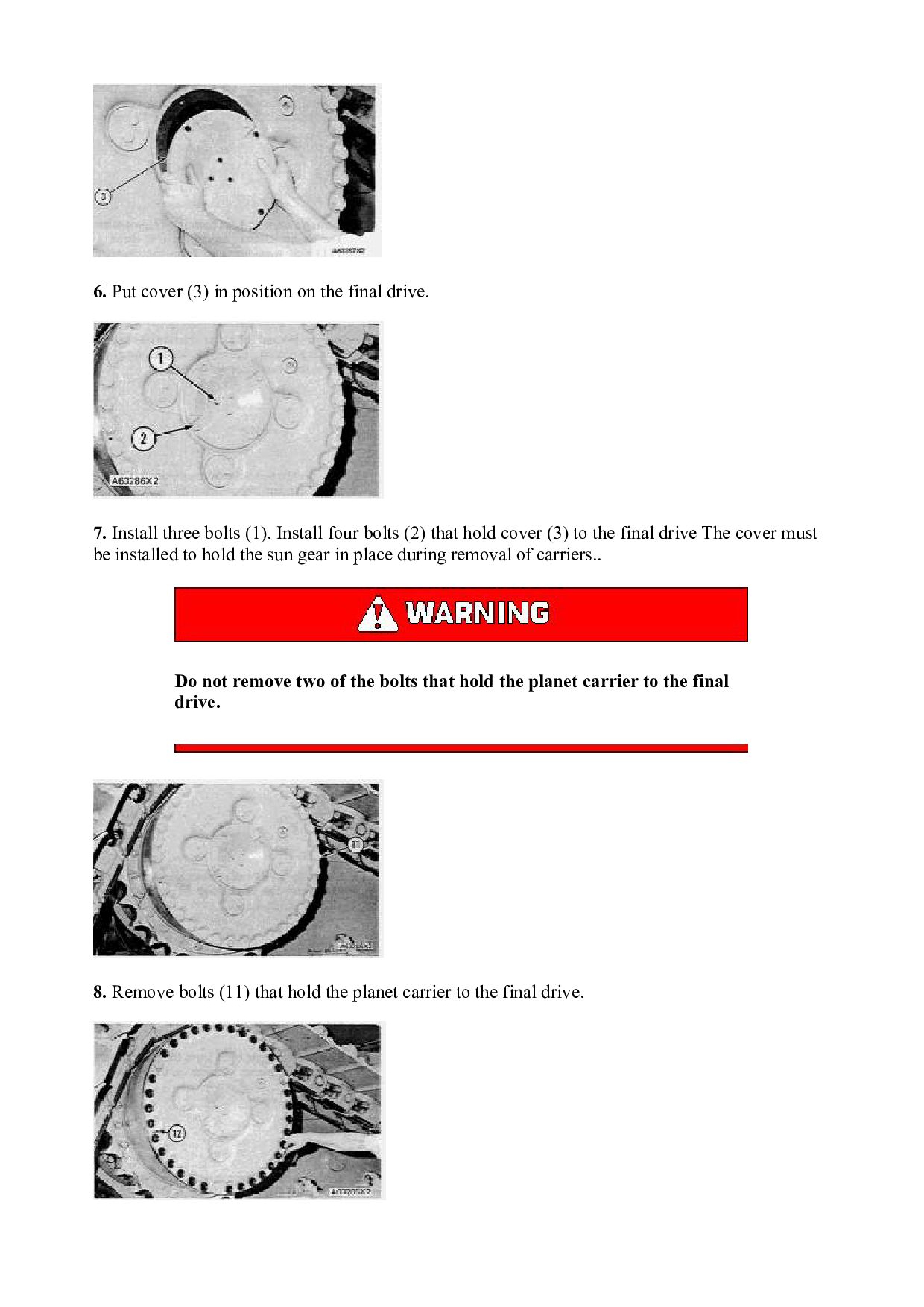
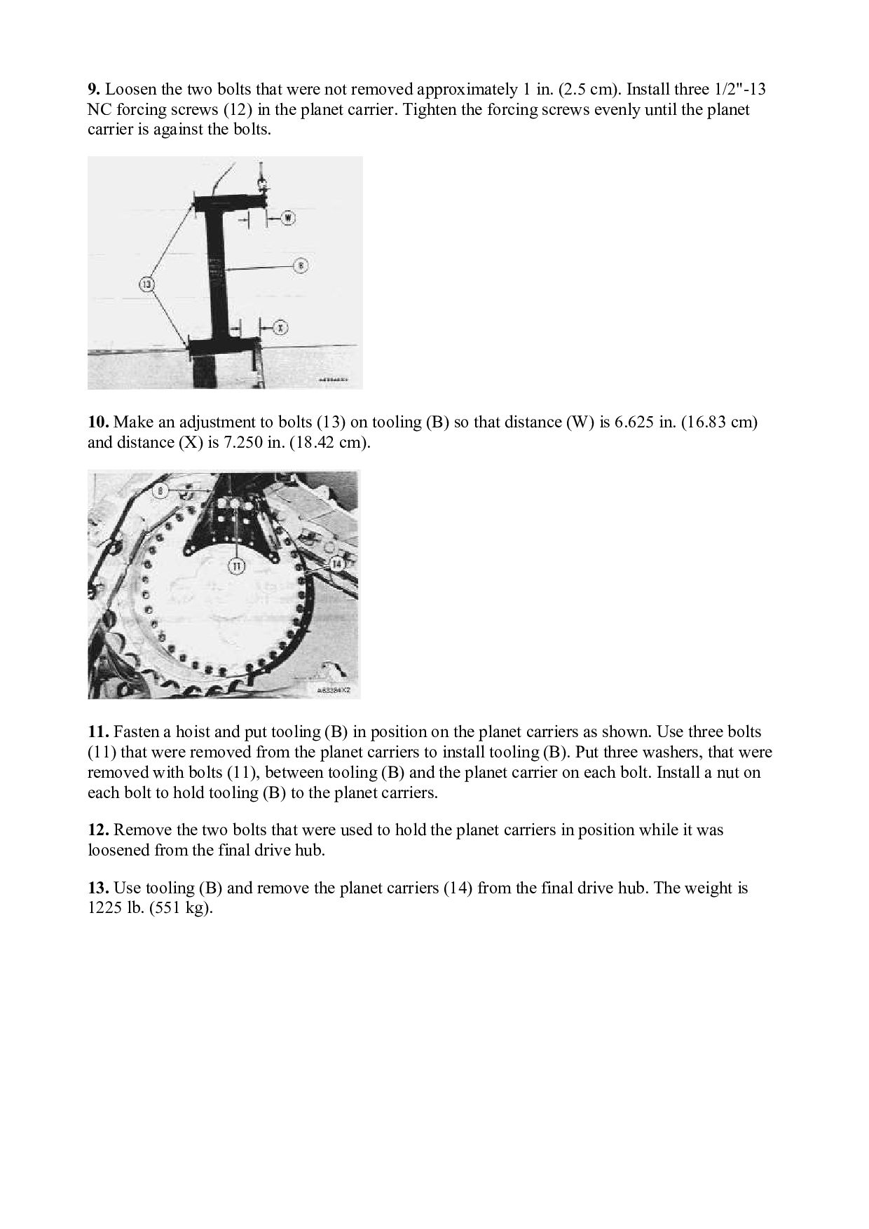
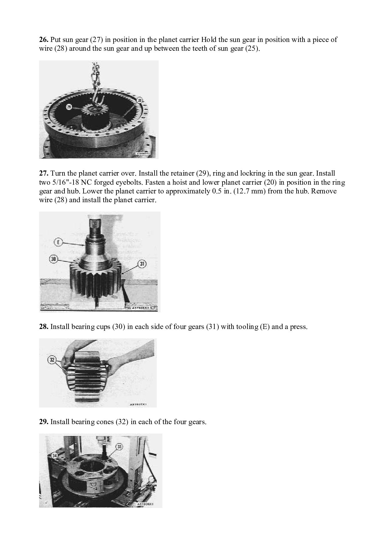
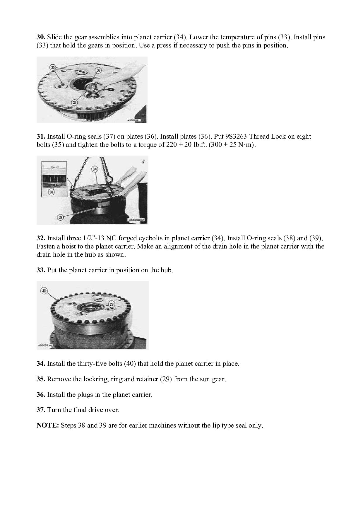
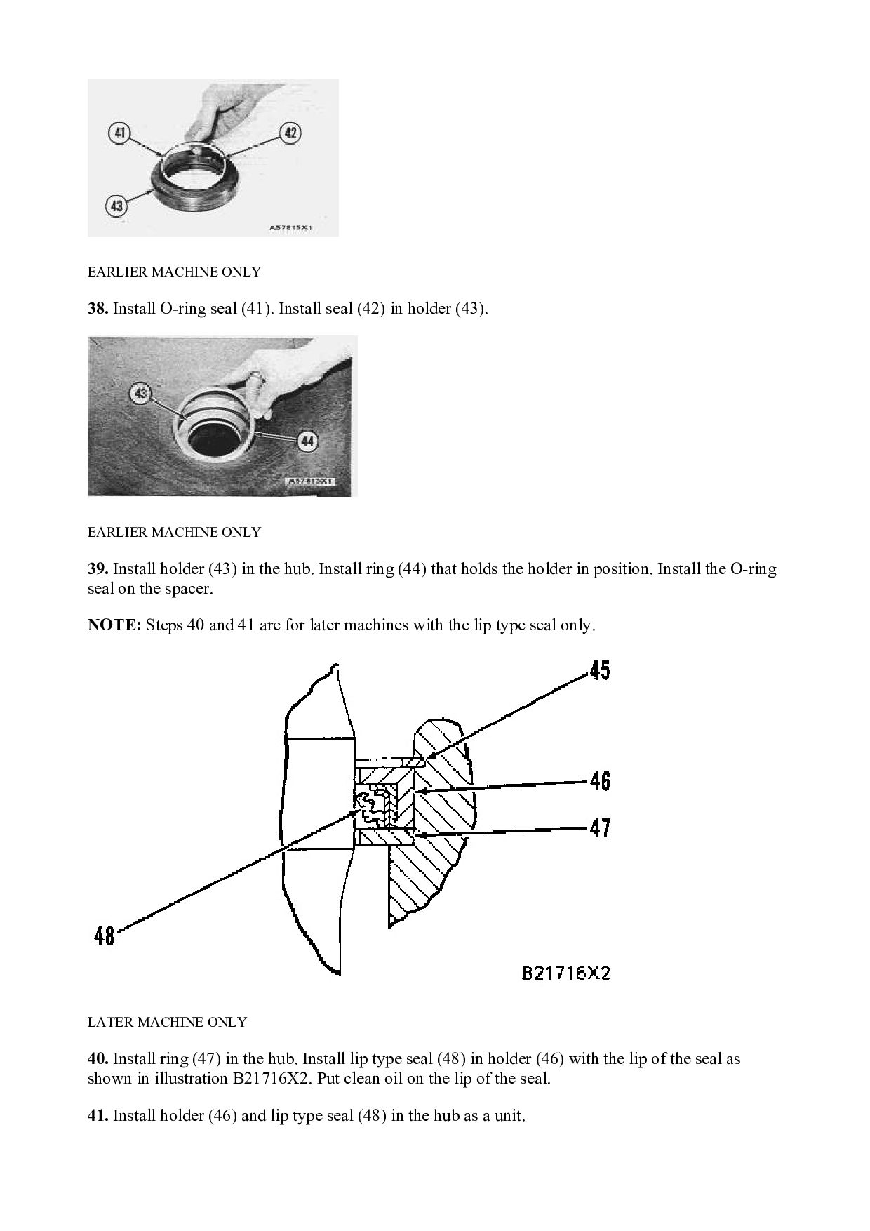
  7. 4. Install three 5/8" bolts (4) that hold the steering

    clutch and brake to the final drive and spacer. 5. Remove tooling (A). Install the two segment bolts and nuts that were removed to install tooling (A). Put 5P3931 Anti-Seize Compound on the threads and tighten the nuts to a torque of 250 ± 50 lb.ft. (340 ± 70 N·m). Tighten the nuts another 1/3 (120°) turn. 6. Install tooling (B) to the outer axle. Fasten a hoist and install outer axle (5). 7. Install O-ring seal (7) and retainer (8). Make alignment of notch (9) in ring (10) with pin (6). Install ring (10). 8. Install spiral lockring (11). Install O-ring seal (13) on cover (12). Put cover (12) in position on the final drive.
  8. 9. Install three bolts (14). Install four bolts (15) that

    hold cover (12) to the final drive. 10. Make sure the drain plug is toward the bottom and fill the final drive with oil to the bottom of the fill plug. See LUBRICATION AND MAINTENANCE GUIDE for correct oil. end by: a) connection of track Disassemble Final Drive start by: a) remove final drive
  9. 1. Install three 5/8"-11 NC forged eyebolts in spacer (1).

    Fasten a hoist and remove spacer (1). The weight of the spacer is 250 lb. (113 kg). 2. Remove the O-ring seal from the spacer ring. NOTE: Steps 3 and 4 are for earlier machine without the lip type seal only. EARLIER MACHINE ONLY 3. Remove the ring that holds holder (2) in place. Remove holder (2) with tool (A). EARLIER MACHINE ONLY 4. Remove seal (3) from holder (2). Remove the O-ring seal from behind the seal. NOTE: Steps 5 and 6 are for later machines with the lip type seal only.
  10. LATER MACHINE ONLY 5. Remove retaining ring (4) from the

    hub. Remove holder (5) and lip type seal (7) from the hub as a unit. Remove lip type seal (7) from holder (5). 6. Remove ring (6) from the hub. 7. Turn the final drive over. Remove thirty-five bolts (8) that hold the planet carrier to the hub. 8. Install three 1/2"-13 NC forcing screws to loosen the planet carrier. Remove the forcing screws and install three 1/2"-13 NC forged eyebolts. Fasten a hoist and remove planet carrier (9). The weight of the planet carrier is 840 lb. (383 kg).
  11. 9. Remove eight bolts (10) and four plates (11). Remove

    the O-ring seals from the plates. 10. Remove the four shafts from the planet carrier with a press and a lift truck for additional support as shown. 11. Use two men to remove gears (12) from the planet carrier. The weight of the gear is 80 lb. (36 kg). 12. Remove bearing cone (13) from each side of gears (12). 13. Remove bearing cup (14) from each side of gears (12) with tooling (B).
  12. 14. Install retainer (15), ring (16) and lockring (17) which

    were removed in REMOVE FINAL DRIVE. This is used to remove the sun gear and planet carrier. 15. Install two 3/8"-16 NC forged eyebolts and fasten a hoist to the retainer. Remove sun gear (18) and planet carrier (19) as a unit from the hub. The weight is 285 lb. (129 kg). 16. Remove spiral lockring (20) from the sun gear. 17. Fasten a hoist and remove planet carrier (19) from sun gear (18). The weight of the planet carrier is 300 lb. (135 kg).
  13. 18. Remove eight bolts (21) and four plates (22). 19.

    Remove four shafts (23) from the planet carrier in a press as shown. 20. Remove four gears (24) from the planet carrier. 21. Remove bearing cone (25) from each side of gears (24). 22. Remove bearing cup (26) from each side of gears (24) with tooling (C).
  14. 23. Remove lockring (27) from each of the gears. 24.

    Remove sun gear (28). 25. Remove thrust bearing (29) from the retainer. 26. Remove sixteen bolts (30) and retainer (31). 27. Remove sixteen pins (32) from the hub.
  15. 28. Install three 3/8"-16 NC forged eyebolts and fasten a

    hoist. Remove the hub and ring gear (33) from hub (34). The weight is 500 lb. (225 kg). 29. Turn the hub and ring gear over. Remove spiral lockring (35) that holds the ring gear to the hub. Install three 3/8"-16 NC forged eyebolts and a hoist (not shown). Remove hub (36) from ring gear (33). 30. Install tooling (D) as shown. Loosen hub (34) from hub (38) approximately 3 in. (7.62 cm) with tooling (D).
  16. 31. Install three 1"-8 NC forged eyebolts in hub (34).

    Fasten a hoist and remove the hub. The weight of the hub is 1000 lb. (450 kg). NOTICE Put hub (34) on blocks to prevent damage to the Duo-Cone seals (39) on the bottom. 32. Remove bearing cone (37) from hub (34). 33. Remove Duo-Cone seal (39) from the hub. Put identification on the seal for correct installation.
  17. 34. Remove one bearing cup (40) from the hub with

    a punch and a hammer. 35. Turn the hub over to remove the other bearing cup (40) from the hub. 36. Remove Duo-Cone seal (41) from hub (38). Put identification on the seal for installation. 37. Do not remove bearing cone (42) only if necessary because it will be destroyed if removed. The weight of hub is 640 lb. (288 kg). Assemble Final Drive
  18. 1. Heat bearing cone (1) to a maximum temperature of

    275°F (135°C). Install bearing cone (1) on hub (2). NOTE: The rubber seals and all surfaces that make contact with the seals must be clean and dry with no damage to the surface. After installation of the seals, put oil on the contact surfaces of the Duo-Cone seals. Put lubrication on all other seals at assembly. 2. Install Duo-Cone seal (3) with tool (A) as shown on the hub. 3. Lower the temperature of bearing cup (4) and install the bearing cup in hub (5). 4. Install Duo-Cone seal (6) in the hub with tool (A). NOTICE
  19. Do not put hub (5) on the Duo-Cone seal. 5.

    Turn hub (5) over and put it on blocks. Lower the temperature of bearing cup (7). Install the bearing cup in hub (5). 6. Install three 1"-8 NC forged eyebolts in hub (5). Fasten a hoist to the hub. Put hub (5) in position on hub (2) as shown. 7. Heat bearing cone (8) to a maximum temperature of 275°F (135°C). Install the bearing cone on the hub.
  20. 8. Put tool (B) in position on the bearing cone.

    Install retainer (9). Turn hub (5) while the bolts that hold the retainer are tightened to a torque of 100 lb.ft. (135 N·m). Let the bearing cone return to room temperature. NOTICE Do not turn hub (5) until Step 15. 9. Remove retainer (9) from the hub. Measure the distance from the hub to the inner bearing race as shown. Measure the length of pins (13). Each pin must be .003 ± .002 in. (0.08 ± 0.05 mm) less than the measured distance from the hub to the inner bearing race. 10. Install three 3/8"-16 NC forged eyebolts in hub (10). Put hub (10) in position in gear (11).
  21. 11. Install spiral lockring (12) that holds the hub in

    the gear. 12. Turn the hub and gear over. Install three 3/8"-16 NC forged eyebolts and install hub and gear (11). 13. Install sixteen pins (13) in the hub. 14. Install retainer (9) on the hub. Put 9S3263 Thread Lock on bolts (14) and tighten the bolts to a torque of 100 ± 11 lb.ft. (135 ± 15 N·m).
  22. 15. Measure the distance between retainer (9) and pins (13).

    The clearance must be .003 ± .002 in. (0.08 ± 0.05 mm). 16. Install tooling (C) as shown between hubs (5) and (2). Install three 1"-8 NC forged eyebolts in hub (5). Lift up on the hub with a hoist. There must be no movement between the two hubs. 17. Install thrust bearing (15) on the retainer. 18. Install lockring (16) in each of the four gears (17).
  23. 19. Install bearing cups (18) with tool (D) and a

    press in each side of gears (17). 20. Install bearing cones (19) in gears (17). 21. Slide the gear assemblies in planet carrier (20). Lower the temperature of pins (21). Install pins (21) that hold the gears in position. Use a press if necessary to push the pins in position. 22. Measure the distance that pins (21) extend past counterbore (22). The distance must be .003 ± .002 in. (0.08 ± 0.05 mm).
  24. 23. Install plates (24) on the planet carrier. Put 9S3263

    Thread Lock on bolts (23) and tighten the bolts to a torque of 220 ± 20 lb.ft. (300 ± 25 N·m). 24. Fasten a hoist to planet carrier (20). Lower the planet carrier in position on sun gear (25) as shown. 25. Install spiral lockring (26) that holds sun gear (25) to planet carrier (20).
  25. 26. Put sun gear (27) in position in the planet

    carrier Hold the sun gear in position with a piece of wire (28) around the sun gear and up between the teeth of sun gear (25). 27. Turn the planet carrier over. Install the retainer (29), ring and lockring in the sun gear. Install two 5/16"-18 NC forged eyebolts. Fasten a hoist and lower planet carrier (20) in position in the ring gear and hub. Lower the planet carrier to approximately 0.5 in. (12.7 mm) from the hub. Remove wire (28) and install the planet carrier. 28. Install bearing cups (30) in each side of four gears (31) with tooling (E) and a press. 29. Install bearing cones (32) in each of the four gears.
  26. 30. Slide the gear assemblies into planet carrier (34). Lower

    the temperature of pins (33). Install pins (33) that hold the gears in position. Use a press if necessary to push the pins in position. 31. Install O-ring seals (37) on plates (36). Install plates (36). Put 9S3263 Thread Lock on eight bolts (35) and tighten the bolts to a torque of 220 ± 20 lb.ft. (300 ± 25 N·m). 32. Install three 1/2"-13 NC forged eyebolts in planet carrier (34). Install O-ring seals (38) and (39). Fasten a hoist to the planet carrier. Make an alignment of the drain hole in the planet carrier with the drain hole in the hub as shown. 33. Put the planet carrier in position on the hub. 34. Install the thirty-five bolts (40) that hold the planet carrier in place. 35. Remove the lockring, ring and retainer (29) from the sun gear. 36. Install the plugs in the planet carrier. 37. Turn the final drive over. NOTE: Steps 38 and 39 are for earlier machines without the lip type seal only.
  27. EARLIER MACHINE ONLY 38. Install O-ring seal (41). Install seal

    (42) in holder (43). EARLIER MACHINE ONLY 39. Install holder (43) in the hub. Install ring (44) that holds the holder in position. Install the O-ring seal on the spacer. NOTE: Steps 40 and 41 are for later machines with the lip type seal only. LATER MACHINE ONLY 40. Install ring (47) in the hub. Install lip type seal (48) in holder (46) with the lip of the seal as shown in illustration B21716X2. Put clean oil on the lip of the seal. 41. Install holder (46) and lip type seal (48) in the hub as a unit.
  28. 42. Install ring (45). 43. Install three 5/8"-11 NC forged

    eyebolts and put spacer (49) in position on the hub. Install the three bolts and washers that hold the spacer in position. end by: a) install final drive Copyright 1993 - 2021 Caterpillar Inc. All Rights Reserved. Private Network For SIS Licensees. Sun Nov 21 23:11:12 UTC+0800 2021
  29. Shutdown SIS Previous Screen Product: TRACK-TYPE TRACTOR Model: D10 TRACK-TYPE

    TRACTOR 84W Configuration: D10 TRACTOR 84W00001-00645 (MACHINE) POWERED BY D348 ENGINE Disassembly and Assembly D10 TRACTOR POWER TRAIN Media Number -SENR7491-02 Publication Date -01/07/1981 Date Updated -15/07/2005 SENR74910017 Final Drive Planet Carriers, Hub And Ring Gear (In Chassis) SMCS - 4054-12; 4054-11; 4092 Remove Final Drive Planet Carriers, Hub And Ring Gear (In Chassis)
  30. 1. Turn the final drive until drain plug (4) is

    on the bottom as shown. Remove drain plug (4) and drain the oil from the final drive. 2. Remove three bolts (1) from the center of cover (3). Remove four bolts (2) and cover (3) from the final drive. Remove the O-ring seal from cover (3). 3. Remove spiral lockring (5), ring (6) and retainer (7). Remove O-ring seal (8) from retainer (7). 4. Install tool (A) and fasten a hoist as shown. Remove the outer axle. The weight of the outer axle is 85 lb. (39 kg). 5. Install retainer (7). Make alignment of notch (10) in ring (6) with pin (9). Install ring (6). Install spiral lockring (5). This is done to hold the two planet carriers together when removed.
  31. 6. Put cover (3) in position on the final drive.

    7. Install three bolts (1). Install four bolts (2) that hold cover (3) to the final drive The cover must be installed to hold the sun gear in place during removal of carriers.. Do not remove two of the bolts that hold the planet carrier to the final drive. 8. Remove bolts (11) that hold the planet carrier to the final drive.
  32. 9. Loosen the two bolts that were not removed approximately

    1 in. (2.5 cm). Install three 1/2"-13 NC forcing screws (12) in the planet carrier. Tighten the forcing screws evenly until the planet carrier is against the bolts. 10. Make an adjustment to bolts (13) on tooling (B) so that distance (W) is 6.625 in. (16.83 cm) and distance (X) is 7.250 in. (18.42 cm). 11. Fasten a hoist and put tooling (B) in position on the planet carriers as shown. Use three bolts (11) that were removed from the planet carriers to install tooling (B). Put three washers, that were removed with bolts (11), between tooling (B) and the planet carrier on each bolt. Install a nut on each bolt to hold tooling (B) to the planet carriers. 12. Remove the two bolts that were used to hold the planet carriers in position while it was loosened from the final drive hub. 13. Use tooling (B) and remove the planet carriers (14) from the final drive hub. The weight is 1225 lb. (551 kg).
  33. 14. Remove sun gear (15) from the planet carrier and

    put the planet carriers on the floor. 15. To disassemble the planet carriers see DISASSEMBLE FINAL DRIVE. 16. Remove bearing (16) from the retainer. 17. Install tooling (C) under the final drive hub to hold it in position when the retainer is removed. Make sure tool (D) is in position to hold the hub and ring gear in place when the retainer is removed. Use one of the bolts that hold the planet carriers in place to hold tool (D).
  34. 18. Remove sixteen bolts (17) and retainer (18) from the

    final drive. 19. Use a magnet and remove sixteen pins (19) from the hub. NOTE: Make sure that the short support of tooling (E) is on top and the long support is on the bottom when distances (Y) and (Z) are made. 20. Make an adjustment to bolts (20) on tooling (E) so that distance (Y) is 7.250 in. (18.42 cm) and distance (Z) is 6.625 in. (16.83 cm). 21. Put tooling (E) in position against the hub. Install two 3/8"-16 NC forged eyebolts in two of the three threaded holes in the hub. Use ratchet assembly (21) [part of tooling (E)] fastened between the eyebolts and tooling (E) to hold the hub and ring gear to the tooling. Remove tool
  35. Thank you very much for your reading. Please Click Here.

    Then Get COMPLETE MANUAL. NO WAITING NOTE: If there is no response to click on the link above, please download the PDF document first and then click on it.
  36. (D). Remove hub and ring gear (22) from the final

    drive hub. The weight is 500 lb. (225 kg). Remove the spiral lockring from the back side of the hub to remove the ring gear from the hub. Install Final Drive Planet Carriers, Hub And Ring Gear (In Chassis) 1. Install tool (A) and retainer (1) on the final drive hub as shown.
  37. 2. Tighten sixteen bolts (2) to a torque of 100

    lb. ft. (135 N·m). This is done to put the bearings in the correct position on the final drive hub. 3. Remove the sixteen bolts and retainer (1) and tooling (A). 4. Install three 3/8"-16 NC forged eyebolts in hub (3). Put hub (3) in position in ring gear (4). 5. Install spiral locking (5) that holds the hub in the ring gear. 6. Install two 3/8"-16 NC forged eyebolts in the threaded holes in the hub. Put tooling (C) in position on the hub and ring gear. Use 5P9694 Ratchet Hoist (6) to hold tooling (C) to the hub. Install the hub and ring gear on the splines of the final drive hub. 7. Install tool (D) with one of the bolts used to hold the planet carriers to the final drive hub. Remove tooling (C).
  38. 8. Install sixteen pins (7) in hub (3). 9. Install

    retainer (1) on the hub. Put 9S3263 Thread Lock on bolts (2) and tighten the bolts to a torque of 100 lb. ft. (135 N·m). 10. Remove tooling (B) and (D). 11. Measure the distance between retainer (1) and the hub with a feeler gauge as shown. There must be no clearance between the retainer and the hub. 12. Install thrust bearing (8) on the retainer. 13. For assembly of planet carriers: See ASSEMBLE FINAL DRIVE.
  39. https://www.aservicemanualpdf.com/ My Dear Friend! Thank you very much for visiting.

    Full manual if required, please enter the following URL into your browser. https://www.aservicemanualpdf.com/