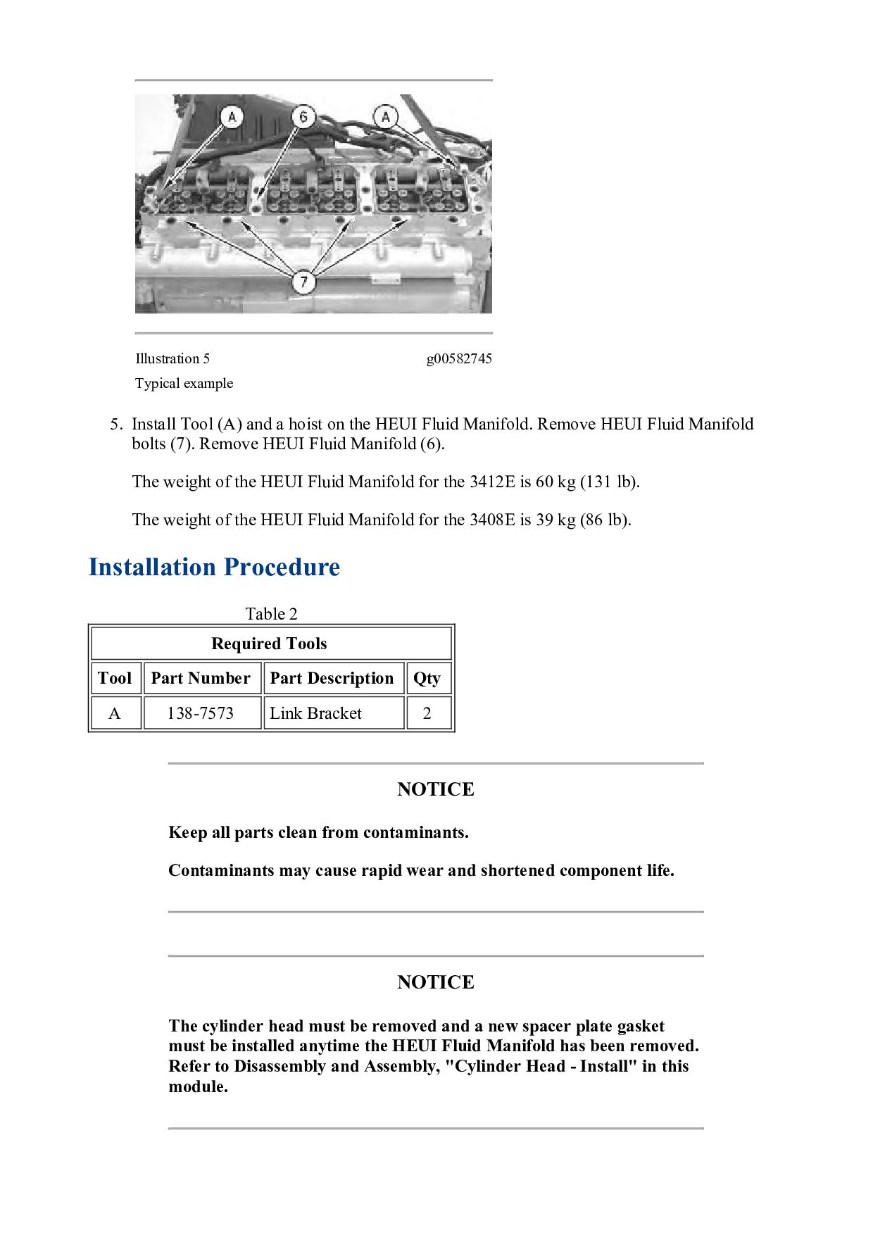
TRACTOR 2YD Configuration: D10N TRACK-TYPE TRACTOR 2YD00001-UP (MACHINE) POWERED BY 3412 ENGINE Disassembly and Assembly 3408E and 3412E Engines for Caterpillar Built Machines Media Number -RENR2336-06 Publication Date -01/08/2018 Date Updated -10/08/2018 i01105362 HEUI Fluid Manifold - Remove and Install SMCS - 1126-010 Removal Procedure Table 1 Required Tools Tool Part Number Part Description Qty A 138-7573 Link Bracket 2 Start By: a. Remove the injection actuation pressure sensor. Refer to Disassembly and Assembly, "Injection Actuation Pressure Sensor - Remove and Install". b. Remove the unit injector sleeves. Refer to Disassembly and Assembly, "Unit Injector Sleeve - Remove". c. Remove the rocker arm and shaft. Refer to Disassembly and Assembly, "Rocker Arm and Shaft - Remove". d. Remove the valve mechanism cover base. Refer to Disassembly and Assembly, "Valve Mechanism Cover Base - Remove and Install". e. Remove the aftercooler. Refer to Disassembly and Assembly, "Aftercooler - Remove". NOTICE Care must be taken to ensure that fluids are contained during performance of inspection, maintenance, testing, adjusting and repair of the product. Be prepared to collect the fluid with suitable containers