Upgrade to Pro — share decks privately, control downloads, hide ads and more …

Caterpillar_Cat_D10N_Track-Type_Tractor__Prefix_3SK__Service_Repair_Manual__3SK00001_and_up_.pdf

dcfv
May 22, 2024
3

 Caterpillar_Cat_D10N_Track-Type_Tractor__Prefix_3SK__Service_Repair_Manual__3SK00001_and_up_.pdf

dcfv

May 22, 2024
Tweet

More Decks by dcfv

Transcript

  1. Shutdown SIS Previous Screen Product: TRACK-TYPE TRACTOR Model: D10N TRACK-TYPE

    TRACTOR 3SK Configuration: D10N Track-Type Tractor 3SK00001-UP (MACHINE) POWERED BY 3412 Engine Disassembly and Assembly D10N TRACK-TYPE TRACTOR POWER TRAIN Media Number -SENR3516-01 Publication Date -01/08/2004 Date Updated -06/12/2017 SENR35160018 Final Drives SMCS - 4050-011; 4050-012; 4050-015; 4050-016 Remove Final Drives Start By: a. separation of tracks NOTE: The final drive planetary carriers can be removed in chassis. See Remove Final Drive Planetary Carriers (In Chassis). 1. Turn the final drive until drain plug (1) is on the bottom as shown. Remove drain plug (1), and drain the oil from the final drive.
  2. 2. Remove three bolts (3) from the center of cover

    (4). Remove three bolts (2) and cover (4) from the final drive. Remove the O-ring seal from the cover. 3. Remove spiral lock ring (5), ring (8) and retainer (6). Remove O-ring seal (7) from retainer (6). 4. Install tool (A) on the outer axle, and fasten a hoist as shown. Remove the outer axle. NOTICE
  3. Make sure that the short support of tooling (B) is

    on the bottom, and the long support is on the top when distances (M) and (N) are made. 5. Make an adjustment to bolts (9) on tooling (B) so distance (M) is 75 mm (2.95 in) and distance (N) is 180 mm (7.08 in). Typical Example 6. Remove three bolts from the sprocket segments. Fasten a hoist, and install tooling (B). Make an adjustment to bolts (11) until the bolts are against the final drive hub. 7. Remove bolts (10) that hold the final drive and steering clutch and brake to the frame. NOTICE Do not remove three bolts (12) that hold the steering clutch and brake to the frame. 8. Remove three bolts (13) that hold the final drive and steering clutch and brake together. Typical Example
  4. 9. Remove final drive (14) from the machine. The weight

    of the final drive is approximately 1070 kg (2630 lb). 10. Remove O-ring seal (15) from the steering clutches. Install Final Drives 1. Inspect all O-ring seals for wear or damage, and make replacements if necessary. 2. Put O-ring seal (15) in position on the steering clutches. Typical Example
  5. https://www.aservicemanualpdf.com/ My Dear Friend! Thank you very much for visiting.

    Full manual if required, please enter the following URL into your browser. https://www.aservicemanualpdf.com/
  6. 3. Fasten a hoist and install tooling (B) on the

    final drive. Make an adjustment to tooling (B), if needed, to put the final drive in a level position. 4. Put final drive (14) in position on the tractor. Typical Example 5. Install bolts (10) that hold the final drive in place. Tighten the bolts to a torque of 1125 ± 100 N·m (820 ± 75 lb ft). 6. Install the three 1/2 in bolts that hold the final drive to the steering clutch and brake. 7. Remove tool (B) from the final drive. Put clean SAE 30W oil on the threads of the sprocket segment bolts. Install the bolts and nuts (with the head of the bolts against the final drive). Tighten the nuts to a torque of 340 ± 68 N·m (250 ± 50 lb ft). Tighten the nuts 120° more. Final torque must be a minimum of 884 N·m (650 lb ft). 8. Use tool (A) and a hoist to put the outer axle in position to make an alignment of the splines. 9. Put O-ring seal (7) in position on retainer (6). 10. Put ring (8) and retainer (6) in position in the final drive. 11. Install spiral lock ring (5) that holds ring (8) in place.
  7. 12. Put the O-ring seal in position on the back

    of cover (4). 13. Put cover (4) in position, and install the four bolts (2) that hold the cover in place. Install the three bolts (3) that hold the retainer to the cover. 14. Make sure the drain plug is toward the bottom, and fill the final drive with oil to the bottom of the fill plug. See the Maintenance Guide. End By: a. connection of tracks Disassemble Final Drives Start By: a. remove final drive
  8. 1. Remove bolts (1) that hold carrier (2) in position

    on the final drive. 2. Install tooling (A) on the carrier. Fasten a hoist to tooling (A). 3. Remove carrier (2) from the final drive. The weight of the carrier is approximately 268 kg (590 lb). Remove the O-ring seal from the carrier. 4. Remove bolts (3) and plates (4). 5. Put the carrier assembly in position in a press as shown, and remove shafts (5).
  9. 6. Remove gears (6) from the carrier. 7. Remove bearing

    cones (7) from gears (6). 8. Install tooling (B) on gear (6). 9. Remove bearing cups (8) with tooling (B). NOTE: Retainer (10) and spiral ring (9) were removed in the topic, Remove Final Drives. 10. Put retainer (10) and spiral ring (9) in position on gear (11).
  10. NOTE: There is a sun gear in the middle of

    the planetary carrier that is free to fall if it stays with planetary carrier. 11. Install tooling (A) on the retainer. Remove gear (11) and the planetary carrier with tooling (A) and a hoist. The weight of the gear and planetary carrier is approximately 118 kg (260 lb). 12. Remove spiral ring (12) that holds the gear in position. 13. Remove planetary carrier (13) from gear (14). The weight of the planetary carrier is approximately 100 kg (220 lb). 14. Remove bolts (16) and plates (15). 15. Put the planetary carrier in position in a press, and remove four shafts (17) from the carrier.
  11. 16. Remove gears (18) from the planetary carrier. 17. Remove

    bearing (19) from gears (18). 18. Put tooling (C) in position on the gear assembly as shown. Remove bearing cups (20) from the gear. 19. Remove lock ring (21) from gear (18). 20. Remove sun gear (22) from the final drive.
  12. 21. Remove 16 bolts (23) and retainer plate (24) from

    the hub. 22. Put plate (24) in position in a press. Use tooling (D) and the press to remove the ring. 23. Use a magnet to remove pins (25) from the hub. 24. Put tooling (A) in position on the hub. Fasten a hoist to tooling (A), and remove gear (26) and the hub. The weight of the gear and hub is approximately 188 kg (415 lb).
  13. 25. Remove retainer ring (27) from the gear and hub.

    26. Install tooling (A) on the hub. Fasten a hoist to tooling (A). Remove hub (28) from gear (26). The weight of the hub is approximately 54 kg (120 lb). 27. Put tooling (E) in position on the hub as shown. NOTICE Do not lift the hub high enough to make contact with the fittings on the hydraulic cylinder. 28. Use tooling (E) to remove the sprocket hub and bearing cone (29) from the support hub.
  14. 29. Install three 1" - 8 NC forged eyebolts (30)

    in hub (31). 30. Fasten a hoist to the eyebolts and remove hub (31). The weight of the hub is approximately 410 kg (900 lb). 31. Remove Duo-Cone seal (32) from the hub. 32. Remove bearing cups (33) and (34) from the hub only if necessary. 33. Remove Duo-Cone seal (35) for the hub. NOTE: Bearing (36) will be damaged when it is removed from the hub. 34. If necessary, remove bearing (36) from the hub. 35. Remove lip-type seal (37) from the seal retainer. 36. Remove seal retainer (38) from the hub only if necessary. Assemble Final Drives
  15. 1. Use Tooling (D) in order to install seal (37)

    into seal retainer (38). The lip of seal (37) must be down. 2. Install seal (37) and seal retainer (38) into the hub to a depth of 1 ± 1 mm from surface (X). 3. If bearing (36) was removed from the hub, heat the bearing to a maximum temperature of 135° C (275°F). Install bearing (36) on the hub. NOTE: Before installing any of the Duo-Cone Seals. See Installation of The Conventional Duo- Cone Floating Seals in this module. 4. Put Duo-Cone Seal (35) in position on the hub.
  16. 5. Use tool (F) as shown, and push Duo-Cone seal

    (35) into position. 6. Lower the temperature of bearing cups (33) and (34) and install them in the final drive hub. 7. Put Duo-Cone seal (32) in the hub. Use tool (F) to push Duo-Cone seal (32) into position. 8. Install three 1" - 8 forged eyebolts (30) in final drive hub (31). Fasten a hoist to the eyebolts. Carefully lower the final drive hub into position.
  17. 9. Heat bearing cone (29) to a maximum temperature of

    135°C (275°F). 10. Put tooling (G) in position while bearing cone is hot. 11. Install retainer plate (24) and bolts (23). Tighten the bolts to put the bearing in its correct position. Tighten the bolts to a torque of 135 ± 15 N·m (100 ± 11 lb ft). 12. Leave the plate and bolts in place until the bearing has become cool. 13. Install tooling (A) on hub (28). Fasten a hoist and tooling (A) 14. Lower hub (28) into position in gear (26). 15. Install retainer ring (27) in the groove in the gear. 16. Install tooling (A) on the inside of the hub. Fasten a hoist to tooling (A). Lower the hub and gear (26) into position in the final drive hub.
  18. 17. Put pins (25) in position in the hub. 18.

    Use a straight edge, such as the 7H1941 Base from the 8S2328 Dial Indicator Test Group, to make sure pins (25) and hub (28) are below the surface of hub (39). The pins must be 0 to .127 mm (0 to .005 in) below the surface level of hub (39). None of the pins may protrude above the hub surface. 19. Use a press and tooling (D) to install ring (40) in retainer plate (24). 20. Put retainer plate (24) in position. Install bolts (23) that hold the plate to the hub. Tighten the bolts to a torque of 135 ± 15 N·m (100 ± 11 lb ft). NOTE: There must be metal to metal contact between retainer plate (24) and hub (39).
  19. 21. Install retainer ring (21) in gear (18). 22. Install

    bearing cups (20) in the gear with tooling (D) and a press until the bearings make contact with the retainer ring. 23. Put bearing cones (41) in position in gear. 24. Put gears (18) and the bearing cones in position in carrier (13). 25. Lower the temperature of shafts (17), and install them in the carrier and gears. Use a press, if necessary. Install shafts (17) until the small end of the shaft extends 0.08 ± 0.05 mm (.003 ± .002 in) past the surface of the carrier. This is to make sure that there is a metal to metal contact between shafts (17) and the plates when they are installed.
  20. 26. Install four plates (15) and bolts (16). Tighten the

    bolts to a torque of 55 ± 7 N·m (41 ± 5 lb ft). NOTE: There must be metal to metal contact between shafts (17) and plates (15). Use a feeler gauge to make sure there is a gap of 0.08 ± 0.05 mm (.003 ± .002 in) between plates (15) and the surface of the carrier. 27. After four plates (15) have been installed, use a press to push the plates even with the surface of the carrier. 28. Fasten a hoist to carrier assembly (13). Lower the carrier assembly onto gear (14). 29. Put spiral ring (12) in position in the groove in the gear. 30. Put sun gear (14) in position in the planetary carrier. Use a wire (42) to hold the gear in place when the planetary carrier is installed in the final drive. Install the wire across the bottom of the gear from the outside of the planetary carrier as shown.
  21. 31. Put retainer (10) and the spiral ring in position

    in the gear. 32. Install one of tool (A) on the gear. Fasten a hoist to tooling (A). 33. Align the gears in the planetary carrier with the gear in the hub. Lower the planetary carrier into the final drive. Remove the wire that holds the sun gear in place when the planetary carrier is within 12.7 mm (.50 in) of the original position in the final drive. 34. Use tool (D) and a press to install the bearing races in gear (6). 35. Put two bearings (7) in position in gear (6). 36. Put gears (6) in position in carrier (2). 37. Lower the temperature of shafts (17). Install the shafts in carrier (2) and the gears. If necessary, use a press to install the shafts. Install the shafts until the small end of the shaft extends 0.08 ± 0.05 mm (.003 ± .002 in) past the surface of the carrier. This is to make sure that there is metal to metal contact between shafts (17) and the plates when they are installed.
  22. 38. Put O-ring seals (43) in position in plates (4).

    39. Install plates (4) and bolts (3). Tighten the bolts to a torque of 135 ± 15 N·m (100 ± 11 lb ft). NOTE: There must be metal to metal contact between shafts (17) and plates (4). Use a feeler gauge to make sure there is a gap of 0.08 ± 0.05 mm (.003 ± .002 in) between plates (4) and the surface of the carrier. 40. After four plates (4) have been installed, use a press and push the plates even with the surface of the carriers. 41. Put O-ring seal (44) in position on carrier (2). 42. Install tooling (A) on carrier (2). Fasten a hoist to tooling (A). 43. Lower carrier (2) into position in the final drive. Make an alignment of the drain hole in the carrier with O-ring seal (45) in the final drive hub. 44. Install the bolts that hold the carrier in place. End By: a. install final drives Copyright 1993 - 2021 Caterpillar Inc. All Rights Reserved. Thu Nov 25 20:38:38 UTC+0800 2021
  23. Shutdown SIS Previous Screen Product: TRACK-TYPE TRACTOR Model: D10N TRACK-TYPE

    TRACTOR 3SK Configuration: D10N Track-Type Tractor 3SK00001-UP (MACHINE) POWERED BY 3412 Engine Disassembly and Assembly D10N TRACK-TYPE TRACTOR POWER TRAIN Media Number -SENR3516-01 Publication Date -01/08/2004 Date Updated -06/12/2017 SENR35160019 Steering Clutches And Brakes SMCS - 4100-012; 4100-011 Remove Steering Clutches And Brakes Start By: a. separation of tracks 1. Turn the final drive until drain plug (1) is on the bottom as shown. Remove drain plug (1), and drain the oil from the final drive.
  24. 2. Remove three bolts (3) from the center of cover

    (4). Remove three bolts (2) and cover (4) from the final drive. Remove the O-ring seal from the cover. 3. Remove spiral lockring (5), ring (8) and retainer (6). Remove O-ring seal (7) from retainer (6). 4. Install tool (A) on the outer axle, and fasten a hoist as shown. Remove the outer axle. 5. Install tool (A) on the inner axle, and fasten a hoist. Remove the inner axle.
  25. NOTICE Make sure that the short support of tooling (B)

    is on the bottom and the long support is on the top when distances (M) and (N) are made. 6. Make an adjustment to bolts (9) on tooling (B) so distance (M) is 143 mm (5.63 in) and distance (N) is 104 mm (4.09 in). Typical Example 7. Remove three bolts from the sprocket segments. Fasten a hoist, and install tooling (B). Make an adjustment to bolts (11) until the bolts are against the final drive hub. 8. Remove bolts (10) that hold the final drive and steering clutch and brake to the frame. 9. Remove bolts (12) that hold the steering clutch and brake to the frame. Do not remove bolts (13) that hold the final drive to the steering clutch and brake. If the bolts are removed, it is possible for the units to separate during removal.
  26. Typical Example 10. Remove final drive and steering clutch and

    brake (14) as a unit. The weight of the unit is approximately 1460 kg (3220 lb). Remove the O-ring seal from the steering clutch and brake housing. 11. Remove O-ring seals (15) from the frame. Install Steering Clutches And Brakes 1. Inspect all O-ring seals for wear or damage, and make replacements if necessary. 2. Put O-ring seals (15) in position on the frame. Put the O-ring seal in position on the rear of the steering clutch and brake housing.
  27. Typical Example 3. Fasten a hoist, and install tooling (B)

    on the final drive. Make an adjustment to tooling (B), if needed, to put the final drive and steering clutch and brake in a level position. 4. Put final drive and steering clutch and brake (14) in position on the tractor. Typical Example 5. Install bolts (10) that hold the final drive in place. Tighten the bolts to a torque of 1125 ± 100 N·m (820 ± 75 lb ft). 6. Install the three bolts (12) that hold the steering clutch and brake to the frame. 7. Loosen bolts (11), and remove tooling (B) from the final drive. Put clean SAE 30W oil or an equivalent lubricant on the threads of the sprocket segment bolts. Install the bolts and nuts (with the head of the bolts against the final drive). Tighten the nuts to a torque of 340 ± 68 N·m (250 ± 50 lb ft). Tighten the nuts 120° more. Final torque must be a minimum of 884 N·m (650 lb ft). 8. Use tool (A) and a hoist to put inner axle in position. Make an alignment of the splines. Install the outer axle in the same manner.
  28. 9. Put O-ring seal (7) in position on retainer (6).

    10. Put ring (8) and retainer (6) in position in the final drive. 11. Install spiral lockring (5) that holds ring (8) in place. 12. Put the O-ring seal in position on the back of cover (4). 13. Put cover (4) in position, and install the three bolts (2) that hold the cover in place. Install the three bolts (3) that hold the retainer to the cover. 14. Make sure the drain plug is toward the bottom, and fill the final drive with oil to the bottom of the fill plug. See the Maintenance Guide. End By: a. connection of tracks Copyright 1993 - 2021 Caterpillar Inc. All Rights Reserved. Private Network For SIS Licensees. Thu Nov 25 20:39:33 UTC+0800 2021
  29. Thank you very much for your reading. Please Click Here.

    Then Get COMPLETE MANUAL. NO WAITING NOTE: If there is no response to click on the link above, please download the PDF document first and then click on it.
  30. Shutdown SIS Previous Screen Product: TRACK-TYPE TRACTOR Model: D10N TRACK-TYPE

    TRACTOR 3SK Configuration: D10N Track-Type Tractor 3SK00001-UP (MACHINE) POWERED BY 3412 Engine Disassembly and Assembly D10N TRACK-TYPE TRACTOR POWER TRAIN Media Number -SENR3516-01 Publication Date -01/08/2004 Date Updated -06/12/2017 SENR35160020 Final Drives And Steering Clutches And Brakes SMCS - 4050-029; 4100-015; 4100-016; 4100-029 Separation And Connection Of Final Drives And Steering Clutches And Brakes Start By: a. remove final drives and steering clutches and brakes 1. Remove O-ring seal (1) from the face of the steering clutch and brake.
  31. 2. Install tooling (A) on the steering clutch and brake

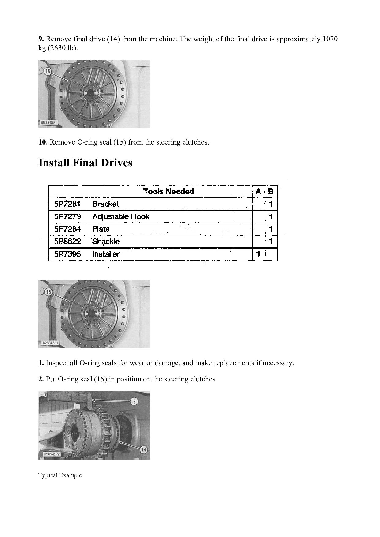
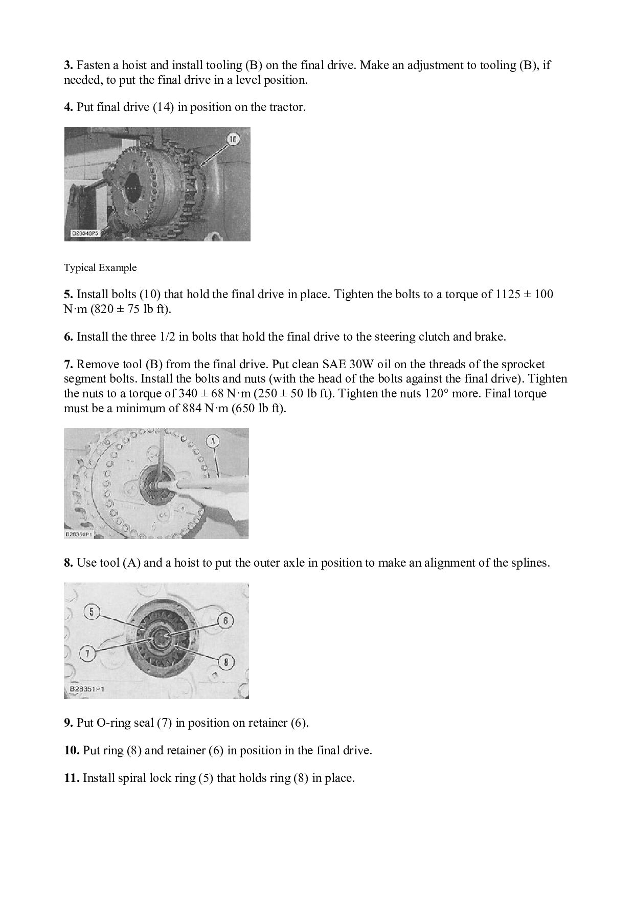
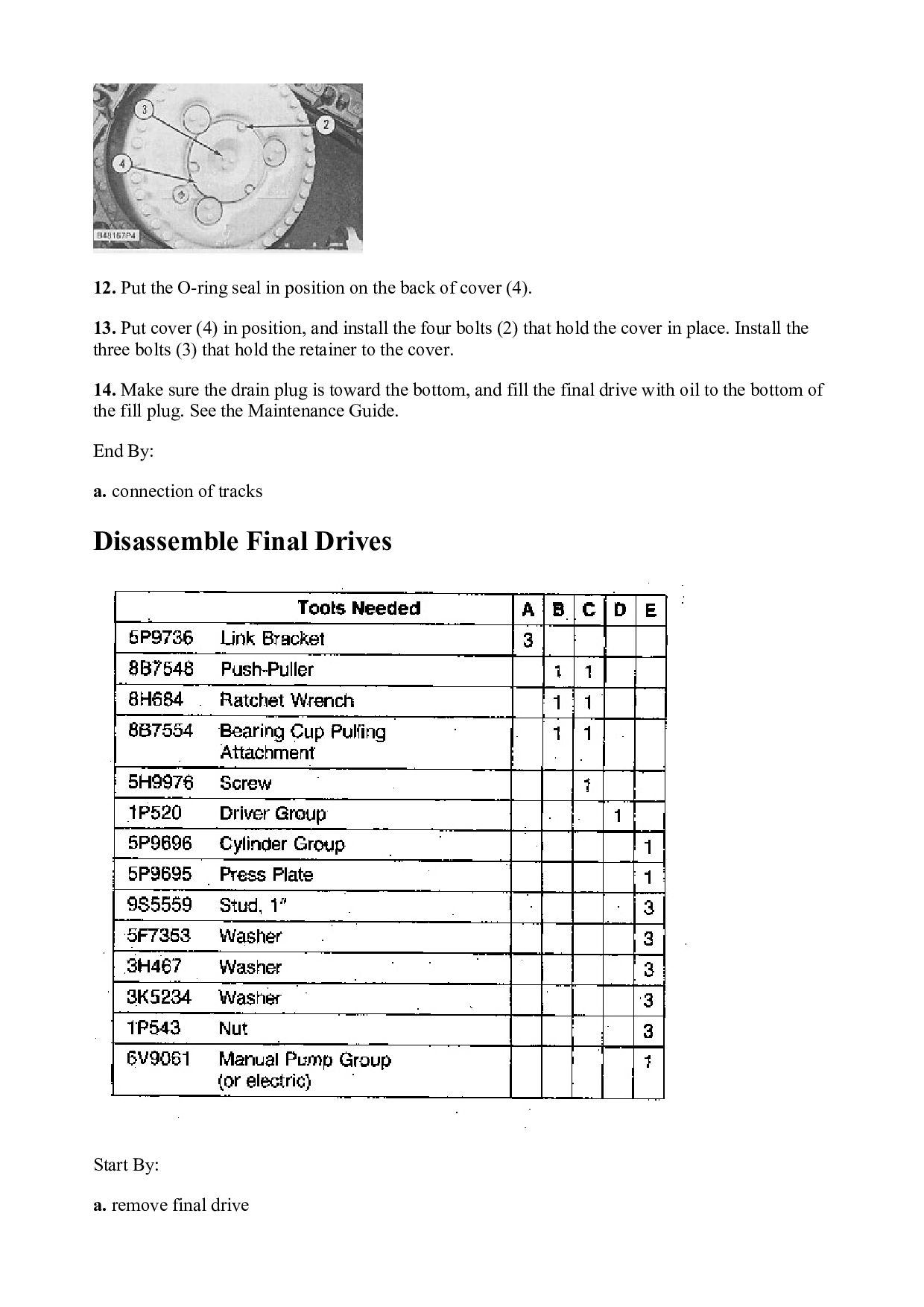
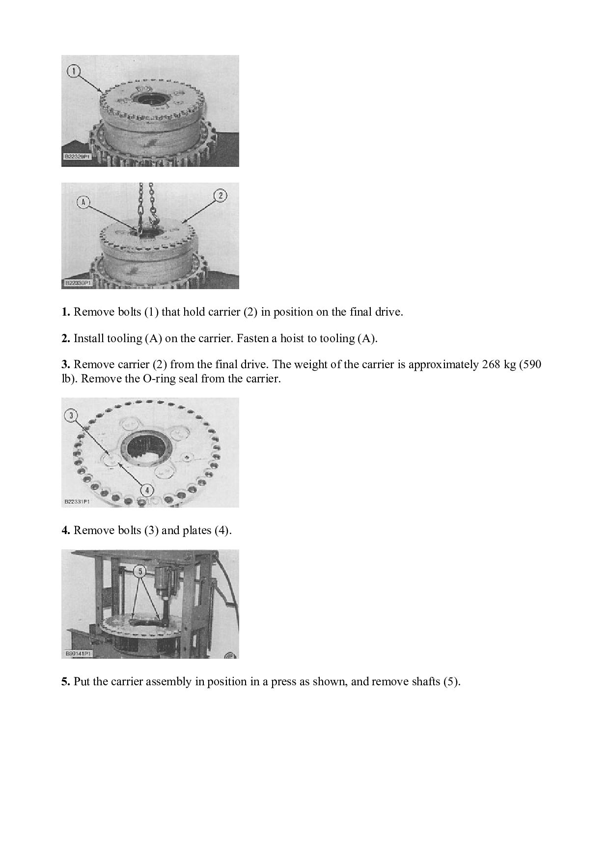
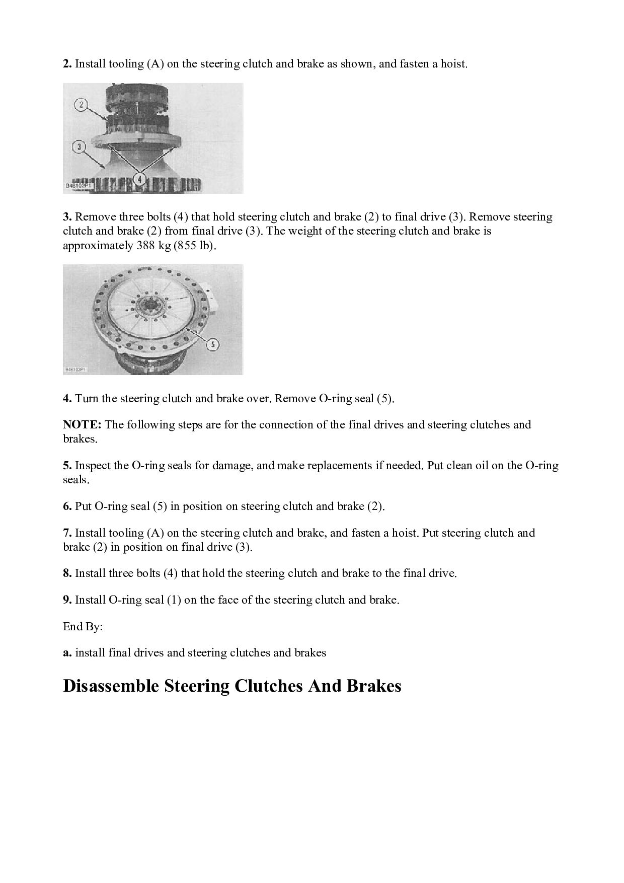
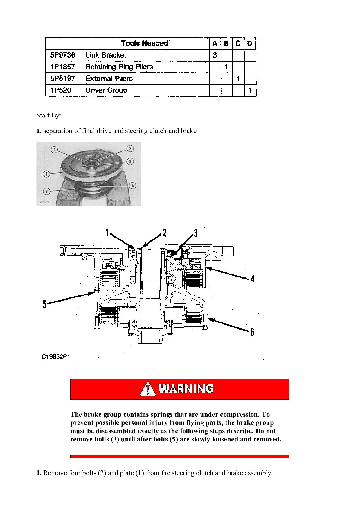
    as shown, and fasten a hoist. 3. Remove three bolts (4) that hold steering clutch and brake (2) to final drive (3). Remove steering clutch and brake (2) from final drive (3). The weight of the steering clutch and brake is approximately 388 kg (855 lb). 4. Turn the steering clutch and brake over. Remove O-ring seal (5). NOTE: The following steps are for the connection of the final drives and steering clutches and brakes. 5. Inspect the O-ring seals for damage, and make replacements if needed. Put clean oil on the O-ring seals. 6. Put O-ring seal (5) in position on steering clutch and brake (2). 7. Install tooling (A) on the steering clutch and brake, and fasten a hoist. Put steering clutch and brake (2) in position on final drive (3). 8. Install three bolts (4) that hold the steering clutch and brake to the final drive. 9. Install O-ring seal (1) on the face of the steering clutch and brake. End By: a. install final drives and steering clutches and brakes Disassemble Steering Clutches And Brakes
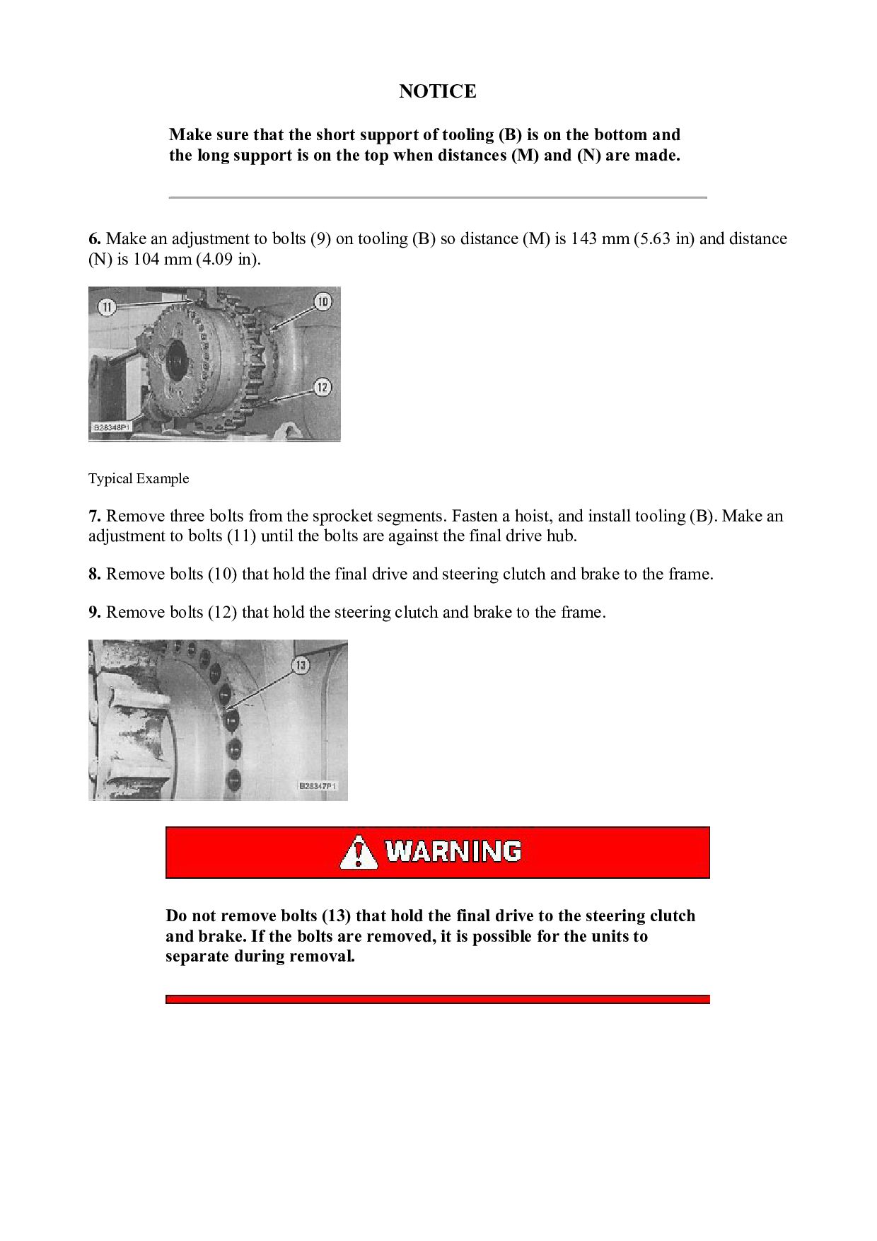
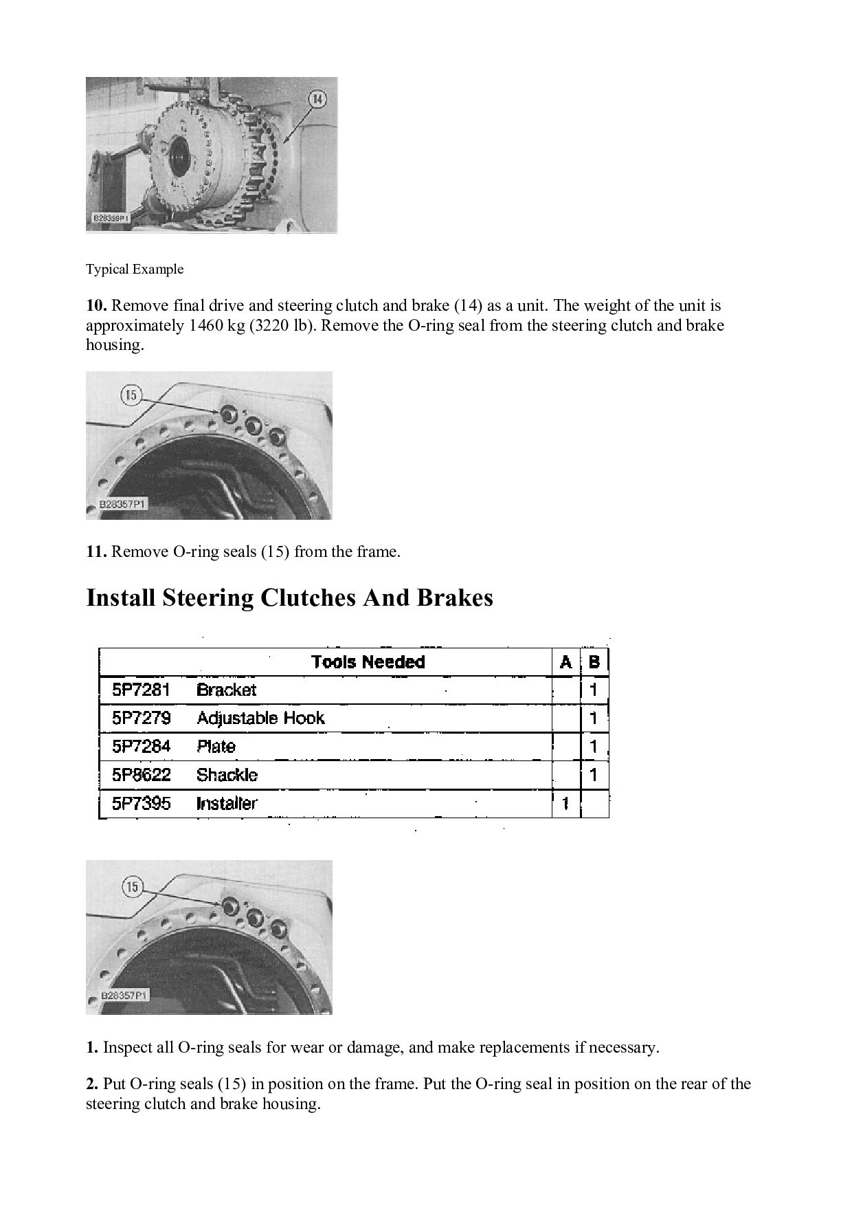
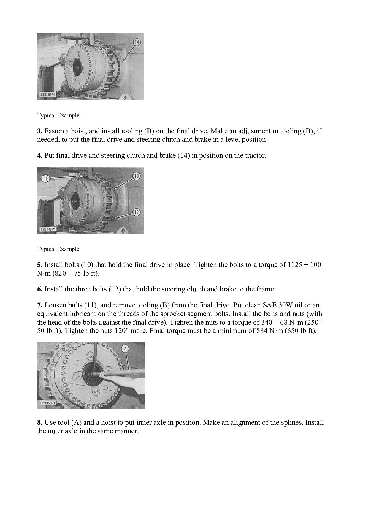
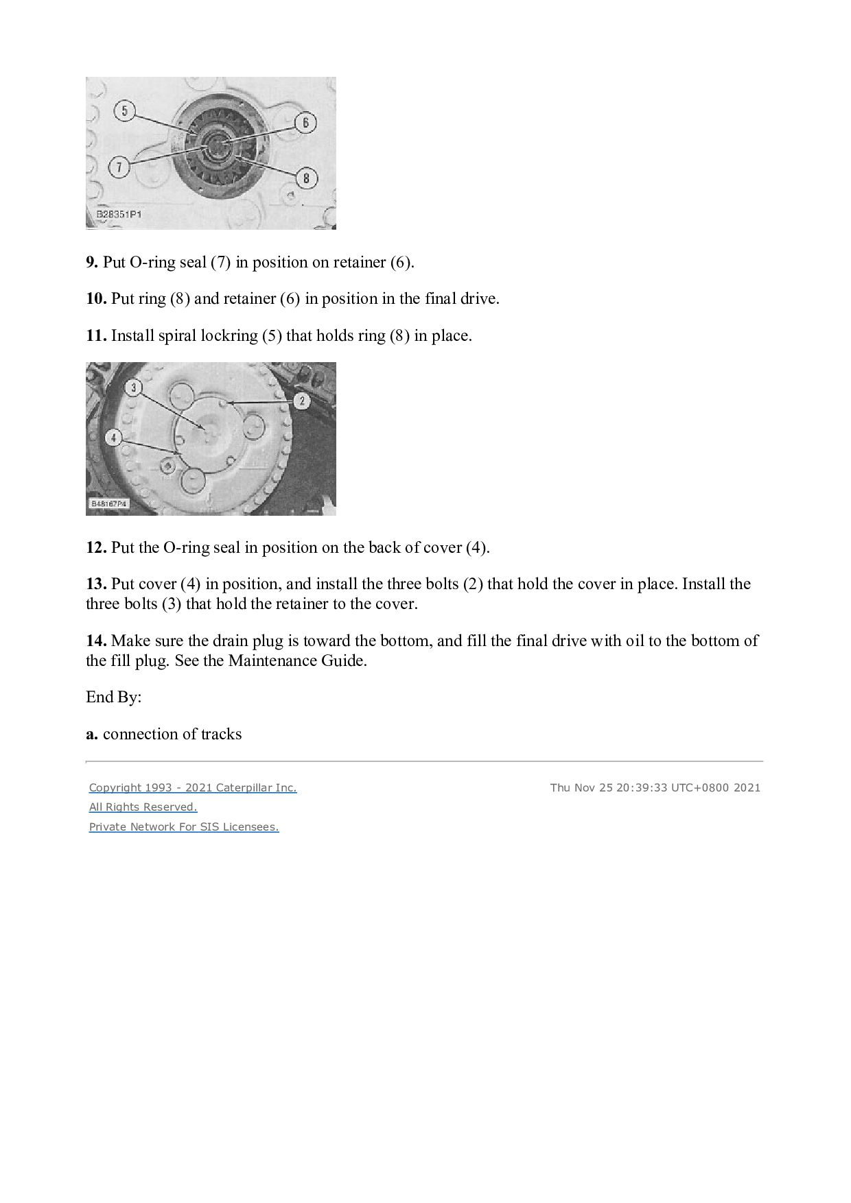
  32. Start By: a. separation of final drive and steering clutch

    and brake The brake group contains springs that are under compression. To prevent possible personal injury from flying parts, the brake group must be disassembled exactly as the following steps describe. Do not remove bolts (3) until after bolts (5) are slowly loosened and removed. 1. Remove four bolts (2) and plate (1) from the steering clutch and brake assembly.
  33. https://www.aservicemanualpdf.com/ My Dear Friend! Thank you very much for visiting.

    Full manual if required, please enter the following URL into your browser. https://www.aservicemanualpdf.com/