Upgrade to Pro — share decks privately, control downloads, hide ads and more …

Caterpillar_Cat_D10_TRACK-TYPE_TRACTOR__Prefix_76X__Service_Repair_Manual__76X00359_and_up_.pdf

dcfv
May 22, 2024
5

 Caterpillar_Cat_D10_TRACK-TYPE_TRACTOR__Prefix_76X__Service_Repair_Manual__76X00359_and_up_.pdf

dcfv

May 22, 2024
Tweet

More Decks by dcfv

Transcript

  1. Shutdown SIS Previous Screen Product: TRACK-TYPE TRACTOR Model: D10 TRACK-TYPE

    TRACTOR 76X Configuration: D10 TRACTOR / POWER SHIFT / 76X00359-UP (MACHINE) POWERED BY D348 ENGINE Disassembly and Assembly D10 Tractor Vehicle Systems Media Number -SENR7671-01 Publication Date -01/06/1982 Date Updated -12/10/2001 Pump Drive SMCS - 3108-11; 3108-12; 3108-15; 3108-16 Remove Pump Drive START BY: a) remove rear bottom guard * b) remove air conditioner compressor c) remove alternator d) remove fan drive pump e) remove implement pump f) remove drive shaft for pump drive g) remove transmission torque converter and steering clutch scavenge pump * h) remove transmission and torque converter charging pump * *Operation location is in POWER TRAIN DISASSEMBLY AND ASSEMBLY section.
  2. 1. Remove bracket (1) from the pump drive. 2. Remove

    vee belts (2). 3. Remove five bolts (3) and drive shaft guard bracket (4). 4. Disconnect oil lines (5) and (6) from the pump drive. 5. Install tooling (A) on the top inside of the cab. Install nylon strap (7) to pump drive (8) and tooling (A).
  3. 6. Disconnect oil line (9) from the pump drive. 7.

    Remove bolts (10) that hold the bottom mounting assembly to the frame. 8. Remove two bolts (11) that hold the top mounting assembly to the frame. 9. Use tooling (A) and remove pump drive (8) from the machine. The weight is 245 lb. (111 kg). Install Pump Drive 1. Use tooling (A) and a nylon strap and put pump drive (1) in position against the frame. 2. Install two bolts (2) that hold the top mounting assembly to the frame.
  4. 3. Install bolts (4) that hold the bottom mounting assembly

    to the frame. 4. Connect oil line (3) to the pump drive. 5. Remove tooling (A) and nylon strap (5). 6. Connect oil lines (6) and (7) to the pump drive. 7. Install drive shaft guard bracket (8).
  5. 8. Put vee belts (9) in position on the pulleys.

    9. Install bracket (10) on the pump drive. END BY: a) install transmission and torque converter charging pump * b) install transmission, torque converter and steering clutch scavenge pump * c) install drive shaft for pump drive d) install implement pump e) install fan drive pump f) install alternator g) install air conditioning compressor h) install rear bottom guard * *Operation location is in POWER TRAIN DISASSEMBLY AND ASSEMBLY section. Disassemble Pump Drive
  6. https://www.aservicemanualpdf.com/ My Dear Friend! Thank you very much for visiting.

    Full manual if required, please enter the following URL into your browser. https://www.aservicemanualpdf.com/
  7. START BY: a) remove pump drive 1. Loosen nut (1)

    until washer (2) is approximately-1/8 in. (3.2 mm) away from yoke (3). Do not remove the nut at this time.
  8. 2. Install tooling (A) on the yoke. Use tooling (A)

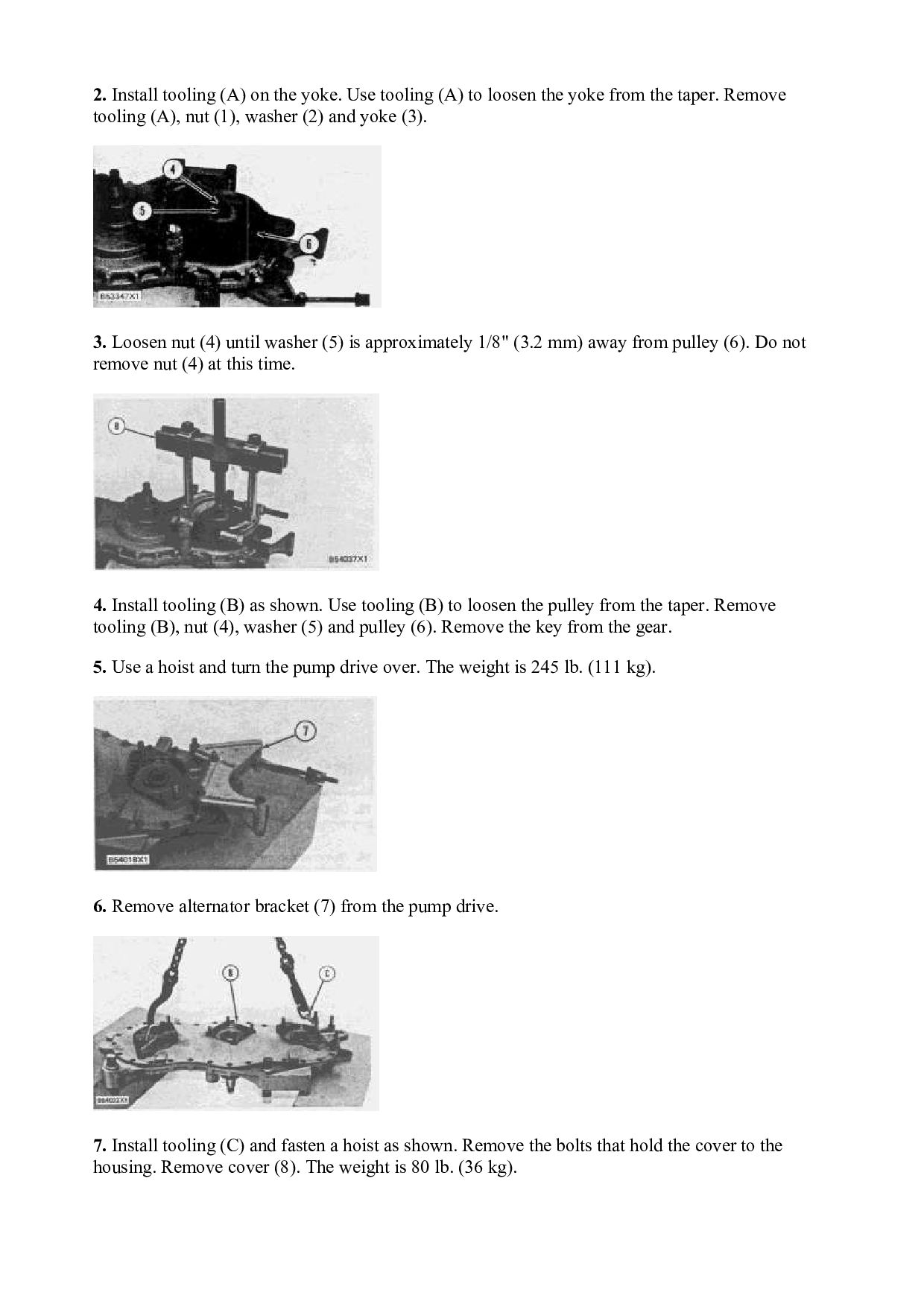
    to loosen the yoke from the taper. Remove tooling (A), nut (1), washer (2) and yoke (3). 3. Loosen nut (4) until washer (5) is approximately 1/8" (3.2 mm) away from pulley (6). Do not remove nut (4) at this time. 4. Install tooling (B) as shown. Use tooling (B) to loosen the pulley from the taper. Remove tooling (B), nut (4), washer (5) and pulley (6). Remove the key from the gear. 5. Use a hoist and turn the pump drive over. The weight is 245 lb. (111 kg). 6. Remove alternator bracket (7) from the pump drive. 7. Install tooling (C) and fasten a hoist as shown. Remove the bolts that hold the cover to the housing. Remove cover (8). The weight is 80 lb. (36 kg).
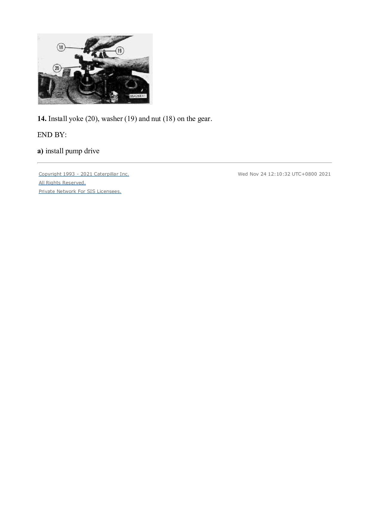
  9. 8. Remove two lip type seals (9) from cover (8).

    9. Use tooling (D) and remove bearing cups (10) from cover (8). 10. Remove gears (11), (12) and (13) from housing (14). 11. Use tooling (E) and remove bearing cone (15) from each side of the gears.
  10. 12. Remove two lip type seals (16) from housing (14).

    13. Use tooling (D) and remove three bearing cups (17) from housing (14). 14. Remove mount assemblies (18) from the housing if a replacement is needed.
  11. Assemble Pump Drive 1. Clean and inspect all parts. Make

    a replacement of the parts if needed. Put clean oil on the lips of the seals, bearing cups and cones and gears. 2. Use tooling (A) and install two lip type seals (1) in housing (2). The lips of the seals must be toward the inside of the housing as shown. Turn the housing over. 3. Lower the temperature of bearing cups (3). Install bearing cups (3) in housing (2). 4. If mount assemblies (4) were removed, install the mount assemblies until the center line of bolt hole is 1.14 ± .010 in. (29.0 ± 0.25 mm) below surface (X). 5. Heat bearing cones (5) to a maximum temperature of 275°F (135°C). Install bearing cones (5) on gear (6).
  12. 6. Heat bearing cones (7) to a maximum temperature of

    275°F (135°C). Install bearing cones (7) on gear (8). 7. Heat bearing cones (9) to a maximum temperature of 275°F (135°C). Install bearing cones (9) on gear (10). 8. Install gears (10), (8) and (6) in housing (2). See the illustrations for the correct way to install the gears in the housing. 9. Lower the temperature of three bearing cups (11). Install three bearing cups (11) in the cover.
  13. 10. Use tooling (A) and install two lip type seals

    (12) in cover (13). The lips of the seals must be toward the inside of the cover as shown. Turn the cover over. NOTE: If the studs were removed from the housing and the cover, install them and tighten the 1/2 in. studs to a torque of 40 ± 7 lb.ft. (55 ± 10 N·m) and 5/8 in. studs to a torque of 75 ± 11 lb.ft. (100 ± 15 N·m). 11. Install tooling (B) to the cover. Fasten a hoist to tooling (B). Put 7M7260 Liquid Gasket Material on the surfaces of housing (2) and cover (13) that make contact with each other. Install cover (13) on housing (2). 12. Install alternator bracket (14) on the pump drive. 13. Install the key in the gear. Make an alignment of the groove in pulley (17) with the key in the gear. Install pulley (17), washer (16) and nut (15).
  14. 14. Install yoke (20), washer (19) and nut (18) on

    the gear. END BY: a) install pump drive Copyright 1993 - 2021 Caterpillar Inc. All Rights Reserved. Private Network For SIS Licensees. Wed Nov 24 12:10:32 UTC+0800 2021
  15. Shutdown SIS Previous Screen Product: TRACK-TYPE TRACTOR Model: D10 TRACK-TYPE

    TRACTOR 76X Configuration: D10 TRACTOR / POWER SHIFT / 76X00359-UP (MACHINE) POWERED BY D348 ENGINE Disassembly and Assembly D10 Tractor Vehicle Systems Media Number -SENR7671-01 Publication Date -01/06/1982 Date Updated -12/10/2001 Pilot Control Valve SMCS - 5059-16; 5059-11; 5059-12; 5059-15 Remove Pilot Control Valve START BY: a) remove seat * *Operation location is in OPERATOR'S STATION DISASSEMBLY AND ASSEMBLY section. Hydraulic oil that is under pressure and hot can cause bodily injury. Move the control levers to relieve the pressure in the hydraulic system. Slowly loosen cap to release any pressure in the hydraulic tank. Let the hydraulic oil become cool before any lines are disconnected in the hydraulic system. 1. Remove cover (1) from the right side console.
  16. 2. Remove bolts (4) that hold the flange retainers (3)

    and boots (2) to the pilot control valve. Pull boots (2) and retainers (3) up on the control rods. 3. Remove cotter pins (6) and pins (7) to disconnect control rods (5) from the valve spools of the pilot control valve. 4. Put identification on all the oil lines connected to the pilot control valve for correct installation. Disconnect all oil lines (10) from the pilot control valve. 5. Remove bolts (9) that hold the pilot control valve to the bracket. Remove pilot control valve (8) from the bracket. Install Pilot Control Valve 1. Install pilot control valve (1) on the bucket.
  17. 2. Connect all oil lines (2) to the pilot control

    valve. 3. Move control rods (3) into position and install pins (5) and cotter pins (4) that connect the control rods to the valve spools of the pilot control valve. 4. Move boots (6) and retainers (7) into position on the flanges. Install bolts (8) that hold the flanges, retainers and boots to the pilot control valve. 5. Install cover (9) on the right side console. END BY: a) install seat *
  18. *This operation location is in OPERATOR'S STATION DISASSEMBLY AND ASSEMBLY

    section. Disassemble Pilot Control Valve START BY: a) remove pilot control valve 1. Remove bolts (4). Make a separation of the manifolds from bulldozer tilt pilot control valve (3), ripper lift pilot control valve (2) and ripper tilt pilot control valve (1). 2. Remove housing (5) from the bulldozer tilt pilot control valve (3). Remove the O-ring seals. 3. Remove O-ring seal (6) and seal (7) from the housing. 4. Remove housing (8) from the bulldozer tilt pilot control valve body.
  19. 5. Remove valve stem (9) from the bulldozer tilt pilot

    control valve body. There is spring pressure against retainers (10). 6. Remove retainers (10) and spring (11) from valve stem (9). 7. Remove housing (12) from ripper lift pilot control valve (2). 8. Remove the O-ring seal and the seal from the housing (see Step 3). 9. Remove housing (13) from ripper lift pilot control valve (2).
  20. 10. Remove valve stem (14) from the ripper lift pilot

    control valve body. There is spring pressure against retainers (16). 11. Remove retainers (16) and spring (17) from valve stem (14). Make a note of hole (15) in stem (14). 12. Follow Steps 7 through 11 to disassemble ripper tilt pilot control valve (1). Assemble Pilot Control Valve 1. Clean and inspect all parts. Make a replacement of the parts that are worn or damaged. Put clean hydraulic oil on the valve parts. NOTE: Follow Steps 2 through 7 to assemble the ripper tilt pilot control valve and the ripper lift pilot control valve. The ripper lift pilot control valve is shown.
  21. 2. Make sure valve stem (1) has hole (2) in

    it. 3. Install spring (4) and retainers (3) on valve stem (1). 4. Put valve stem (1) in position in the valve body. 5. Put the O-ring seal in position in housing (5). Install the housing on the valve body. 6. Use tooling (A) to install seal (7) in housing (6) as shown. Put O-ring seal (8) in position. Put clean hydraulic oil on the lips of seal (7). 7. Put housing (6) in position on the valve body. Put the O-ring seals in position on the valve body.
  22. 8. Install the spring and retainers on valve stem (9).

    9. Put valve stem (9) in position in the bulldozer tilt pilot control valve body. 10. Put the O-ring seal in position in housing (10). Install housing (10) on the bulldozer tilt pilot control valve body. 11. Install the seals in housing (11). See Step 6 for more details. 12. Put housing (11) in position on the bulldozer tilt pilot control valve body. 13. Put the O-ring seals (not shown) in position on manifold (15). 14. Put bulldozer tilt pilot control valve (12), ripper lift pilot control valve (13) and ripper tilt pilot control valve (16) in position. Install manifold (15) and manifold (14). END BY: a) install pilot control valve
  23. Shutdown SIS Previous Screen Product: TRACK-TYPE TRACTOR Model: D10 TRACK-TYPE

    TRACTOR 76X Configuration: D10 TRACTOR / POWER SHIFT / 76X00359-UP (MACHINE) POWERED BY D348 ENGINE Disassembly and Assembly D10 Tractor Vehicle Systems Media Number -SENR7671-01 Publication Date -01/06/1982 Date Updated -12/10/2001 Bulldozer Control Valve SMCS - 6078-11; 6078-12; 6078-15; 6079-16
  24. 1. Remove clamps (1) and (2) that hold hoses (3)

    in place. Move hoses (3) out of the way. NOTE: Put identification on all oil lines for correct installation. 2. Disconnect six oil lines (4) from the front of the bulldozer control valve. 3. Disconnect oil lines (5) from the left side of the bulldozer control valve. 4. Disconnect oil line (8) from the rear of the bulldozer control valve. 5. Disconnect two oil lines (7) from the left side of the bulldozer control valve. 6. Disconnect control rod (6) from the lever on the bulldozer control valve.
  25. Please write to us. Our email: [email protected] Please go to

    the homepage to get the full manual, or other brand PDF manuals. Home Site: aservicemanualpdf.com
  26. Thank you very much for your reading. Please Click Here.

    Then Get COMPLETE MANUAL. NO WAITING NOTE: If there is no response to click on the link above, please download the PDF document first and then click on it.
  27. 7. Remove cover (9) from the right side console. 8.

    Remove bracket (10). 9. Install a 1/2"-13 NC forged eyebolt (11) [part of tooling (A)] in the top rear and center of the cab. Install the 6V2156 Link Bracket [part of tooling (A)] on the top of the bulldozer control valve. Fasten 5P9694 Ratchet Hoist (12) [part of tooling (A)] to the eyebolts and the bracket link. 10. Remove three bolts (14) and washers that hold the bulldozer control valve to the bracket. 11. Use tooling (A) and remove bulldozer control valve (13). The weight is 170 lb. (77 kg). Install Bulldozer Control Valve
  28. 1. Use tooling (A) and put bulldozer control valve (1)

    in position. Make sure washers (2) are in position between the rubber pads and the bulldozer control valve. Install three bolts (7) that hold the bulldozer control valve to the bracket. 2. Install bracket (3). 3. Install cover (4) on the right side console. 4. Connect control rod (5) to the lever on the bulldozer control valve.
  29. 5. Connect two oil lines (6) to the right side

    of the bulldozer control valve. 6. Connect oil line (8) to the rear of the bulldozer control valve. 7. Connect oil lines (9) to the left side of the bulldozer control valve. 8. Connect six oil lines (10) to the front of the bulldozer control valve. 9. Put hoses (11) in their original positions and install clamps (12) and (13). END BY: a) install seat and pressurizer housing Disassemble Bulldozer Control Valve START BY: a) remove bulldozer control valve
  30. https://www.aservicemanualpdf.com/ My Dear Friend! Thank you very much for visiting.

    Full manual if required, please enter the following URL into your browser. https://www.aservicemanualpdf.com/