Upgrade to Pro — share decks privately, control downloads, hide ads and more …

Caterpillar_Cat_CS-683E_Vibratory_Compactor__Prefix_AGR__Service_Repair_Manual__AGR00001_and_up_.pdf

dcfv
May 21, 2024
5

 Caterpillar_Cat_CS-683E_Vibratory_Compactor__Prefix_AGR__Service_Repair_Manual__AGR00001_and_up_.pdf

dcfv

May 21, 2024
Tweet

More Decks by dcfv

Transcript

  1. Shutdown SIS Previous Screen Product: VIBRATORY COMPACTOR Model: CS-683E VIBRATORY

    COMPACTOR AGR Configuration: CS-683E Vibratory Compactor AGR00001-UP (MACHINE) POWERED BY 3056 Engine Disassembly and Assembly CP-663E, CS-663E and CS-683E Vibratory Compactors Machine Systems Media Number -KENR3574-01 Publication Date -01/05/2005 Date Updated -16/05/2005 i05331819 Piston Pump (Propel) - Assemble SMCS - 3203-016; 5070-016; 5070-016-PQ Assembly Procedure Table 1 Required Tools Tools Part Number Part Description Qty A 9U-5719 Shrink Tubing 1 B 128-2741 Alignment Plug 1 C 128-2745 Test Ring 1 D 128-2744 Measuring Bell 1 E 128-2743 Measuring Hub 1 Note: Cleanliness is an important factor. Before assembly, all parts should be thoroughly cleaned in cleaning fluid. Allow the parts to air dry. Wiping cloths or rags should not be used to dry parts. Lint may be deposited on the parts which may cause later trouble. Inspect all parts. If any parts are worn or damaged, use new parts for replacement. Note: Perform Steps 1 through 45 and 51 through 58 in order to assemble the drum propel pump. Note: Perform Steps 1 through 50 in order to assemble the axle propel pump.
  2. Illustration 1 g00834388 Note: Lubricate bearing assembly with the lubricant

    that is being used. 1. Install bearing assembly (96) and retaining ring (97) in housing (58) . Illustration 2 g00834387 Note: Lubricate the sealing lip with the lubricant that is being used. 2. Install seal (95) in housing (58) .
  3. Illustration 3 g00834341 3. Install ring (94) in both sides

    of housing (58) . Illustration 4 g00834339 4. Install O-ring seal (93) on cover (92) . Illustration 5 g00834337 5. Install cover (92) and four bolts (91) on the housing.
  4. Illustration 6 g00834336 6. Install O-ring seal (90) on cover

    (87) . Illustration 7 g00834333 7. Install piston (88) in cover (87) and install nut (89) . Illustration 8 g00834289 8. Install the piston and cover (87) in housing (58) and install four bolts (86) .
  5. https://www.aservicemanualpdf.com/ My Dear Friend! Thank you very much for visiting.

    Full manual if required, please enter the following URL into your browser. https://www.aservicemanualpdf.com/
  6. Illustration 9 g00834287 9. Install the two pins in the

    housing. Install bearing races (82) in the housing. Illustration 10 g00834285 10. Use the following procedure and assemble swashplate assembly (74) . Note: Apply a light coat of petroleum jelly to the bearings for installation purposes. a. Install the roller in bearings (78) and (80) . b. Position pin joint (76) , slide (77) , bearing (78) and wire (81) on cradle (75) . c. Position bearing (80) and wire (79) on cradle (75) .
  7. Illustration 11 g00834284 11. Install swashplate assembly (74) in the

    housing. Note: Bearings (78) and (80) must be seated properly with bearing races (82) . Illustration 12 g00834288 12. Install pin (83) in housing (58) . Note: Wire (79) must go into pin (83) . Note: Use a screwdriver in order to turn pin (83) . Swashplate assembly (74) must move. This will ensure that wire (79) is in pin (83) . 13. Install O-ring seal (85) on plug (84) . Install plug (84) in housing (58) .
  8. Illustration 13 g00834270 14. Install Tooling (A) over shaft (57)

    in order to protect the seal during installation. Carefully install shaft (57) . Remove Tooling (A) . Note: Do not unseat bearings (78) and (80) from bearing races (82) . 15. Install retaining ring (73) . Illustration 14 g00834266 16. Install retaining ring (72) in housing (58) .
  9. Illustration 15 g00834218 Illustration 16 g00834219 17. Install washer (68)

    , spring (71) and washer (69) in cylinder block (64) . 18. Position cylinder block (64) in a press. Install a suitable piece of square steel stock against washer (69) . Use the press and apply slight compression on spring (71) . Install retaining ring (70) and slowly release the spring compression. 19. The following steps are the procedure to determine the correct shim thickness for lift off limitation adjustment of the rotating group:
  10. Illustration 17 g00835074 a. Place port plate (22) onto a

    surface plate. The flat side of the port plate should rest on the surface plate. Illustration 18 g00835078 Illustration 19 g00835082 b. Place Tooling (B) on the inside diameter of port plate (22) . The chamfered side faces upward. c. Install cylinder block (64) onto Tooling (B) and port plate (22) .
  11. Illustration 20 g00835109 d. Install Tooling (C) on top of

    the cylinder block, as shown. Illustration 21 g00835125 e. Make sure that all the springs and shims have been removed from ball joint (65) . Install the ball joint over Tooling (C) . Illustration 22 g00835131 f. Install retainer plate (63) onto ball joint (65) .
  12. Illustration 23 g00835140 Illustration 24 g00586012 g. Bolt Tooling (D)

    and Tooling (E) together. Place Tooling (D) and (E) on top of the retainer plate, as shown. Illustration 25 g00586047
  13. h. Use a Vernier scale height gauge or a similar

    tool in order to measure the dimension in Step 19.i. Illustration 26 g00586062 i. Measure the distance from the top of the surface plate to the top of Tooling (D) . Record this dimension as dimension (X) . Measure the distance from the top of Tooling (D) to the top of retainer plate (63) . Record this dimension as dimension (W) . Table 2 CALCULATION Subtract Dimension (W) from Dimension (X) in order to obtain Dimension (Y) . Dimension (Y) is the Lift Off Limitation Height. Note: The correct Lift Off Limitation Height is 99.96 ± 0.1 mm (3.935 ± 0.004 inch). Call this height Dimension (Z) . Table 3 CALCULATION Subtract Dimension (Y) from Dimension (Z) in order to obtain the thickness of shim (66) . This will provide the correct Lift Off Limitation Height.
  14. Illustration 27 g03377607 20. Install three spring cups (67) in

    the correct sequence. Install shim (66) on top of the springs. Refer to Step 19.i for the correct size. Illustration 28 g00833931 21. Install ball joint (65) on the shim and cylinder block (64) . Illustration 29 g00833929
  15. 22. Install nine pistons (62) and retainer plate (63) in

    cylinder block (64) . Illustration 30 g00681514 23. Wrap a piece of nylon string around the pistons, as shown. Illustration 31 g00835159 24. Lower rotating assembly (59) into the pump. Use the nylon string in order to hold the assembly together during installation. Remove the nylon string.
  16. Illustration 32 g00835161 25. Position the seal and control (60)

    on housing (58) . Install five bolts (61) . Illustration 33 g00835173 Note: The joint of bushing (56) must be at position (Y) . The lubrication grooves of bushing (56) must be in the position of line (X) . 26. Install bushing (56) in the head assembly.
  17. Illustration 34 g00835179 Note: Bushing (55) must be flush with

    face (Z) . 27. Install bushing (55) in the head assembly. Illustration 35 g00833922 28. Install O-ring seal (54) on valve (50) . Illustration 36 g00833921
  18. Illustration 37 g00833920 29. Install O-ring seal (48) on plug

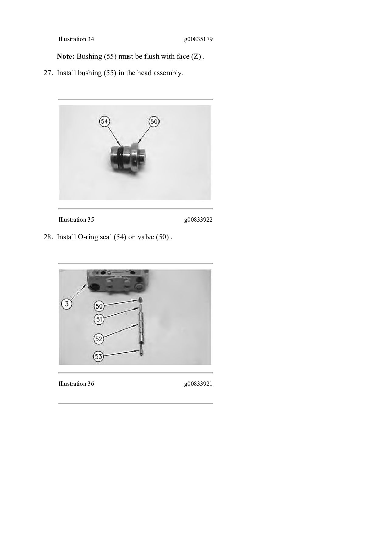
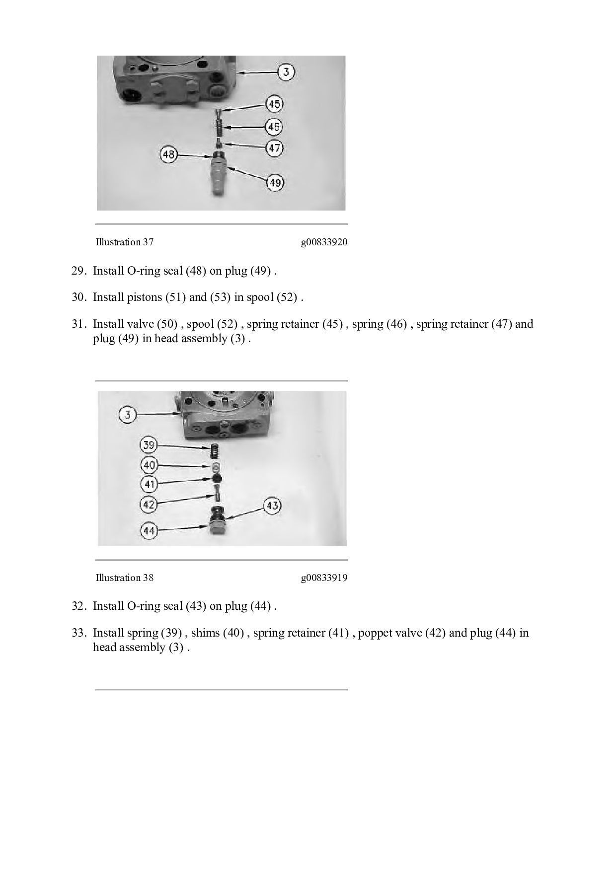
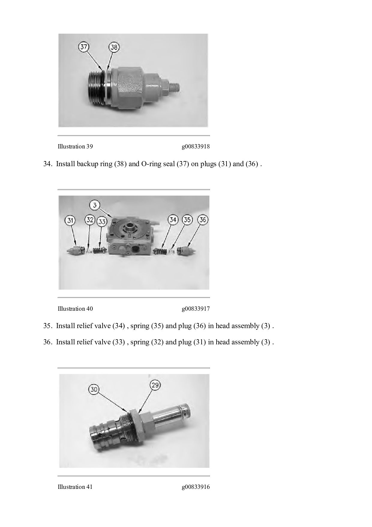
    (49) . 30. Install pistons (51) and (53) in spool (52) . 31. Install valve (50) , spool (52) , spring retainer (45) , spring (46) , spring retainer (47) and plug (49) in head assembly (3) . Illustration 38 g00833919 32. Install O-ring seal (43) on plug (44) . 33. Install spring (39) , shims (40) , spring retainer (41) , poppet valve (42) and plug (44) in head assembly (3) .
  19. Illustration 39 g00833918 34. Install backup ring (38) and O-ring

    seal (37) on plugs (31) and (36) . Illustration 40 g00833917 35. Install relief valve (34) , spring (35) and plug (36) in head assembly (3) . 36. Install relief valve (33) , spring (32) and plug (31) in head assembly (3) . Illustration 41 g00833916
  20. 37. Install O-ring seal (30) on sequence valve (29) .

    Illustration 42 g00833914 38. Install sequence valve (29) in head assembly (3) . Illustration 43 g00833912 39. Remove solenoid assembly (27) and nut (28) on the sequence valve.
  21. Illustration 44 g00833911 Note: Pin (26) must be installed in

    the original orientation. Refer to Disassembly and Assembly, "Piston Pump (Propel) - Disassemble". 40. Install pin (26) in port plate (22) . Illustration 45 g00833910 Note: Port plate (22) must be installed in the original orientation. Refer to Disassembly and Assembly, "Piston Pump (Propel) - Disassemble". Note: Apply a light coat of petroleum jelly to the port plate for installation purposes. 41. Install port plate (22) on head assembly (3) . 42. Install two dowels (25) in head assembly (3) . 43. Install O-ring seals (23) and (24) in head assembly (3) . Illustration 46 g00833909 44. Position head assembly (3) on the housing and install four bolts (21) .
  22. 45. Install seal (20) in head assembly (3) . Illustration

    47 g00833908 46. Install retaining ring (19) in coupling (18) . Illustration 48 g00833907 47. Install plate (17) and coupling (18) in the head assembly.
  23. Illustration 49 g00833905 48. Install O-ring seal (16) in mounting

    flange (13) . Illustration 50 g00833904 49. Install O-ring seal (15) in mounting flange (13) . Illustration 51 g00833902 50. Install mounting flange (13) on the head assembly and install four bolts (14) .
  24. Illustration 52 g00833901 51. Install retaining ring (12) in coupling

    (10) . Illustration 53 g00833899 52. Install woodruff key (11) in coupling (10) . Illustration 54 g00833898 53. Install plate (9) and coupling (10) in head assembly (3) .
  25. Illustration 55 g00833896 54. Install gerotor pump (8) . Illustration

    56 g00833894 55. Install bushing (6) in mounting flange (1) . 56. Install seal (5) and O-ring seal (7) in mounting flange (1) .
  26. Illustration 57 g00833893 57. Install O-ring seal (4) in mounting

    flange (1) . Illustration 58 g00833892 58. Install mounting flange (1) on head assembly (3) and install four bolts (2) . End By: Install the propel pumps. Refer to Disassembly and Assembly, "Piston Pumps (Axle Propel and Drum Propel) - Install". Copyright 1993 - 2021 Caterpillar Inc. All Rights Reserved. Private Network For SIS Licensees. Tue Feb 16 22:27:26 UTC+0800 2021
  27. Shutdown SIS Previous Screen Product: VIBRATORY COMPACTOR Model: CS-683E VIBRATORY

    COMPACTOR AGR Configuration: CS-683E Vibratory Compactor AGR00001-UP (MACHINE) POWERED BY 3056 Engine Disassembly and Assembly CP-663E, CS-663E and CS-683E Vibratory Compactors Machine Systems Media Number -KENR3574-01 Publication Date -01/05/2005 Date Updated -16/05/2005 i01935666 Piston Pumps (Axle Propel and Drum Propel) - Install SMCS - 3203-012; 5070-012 Installation Procedure Illustration 1 g00830718 1. Make sure that the O-ring seal is in place and position drum propel pump (7) on axle propel pump (14). Install two bolts (21) . 2. Install hub (26) on the shaft of axle propel pump (14). Install the hub and maintain a dimension of 30.8 ± 1.0 mm (1.21 ± 0.04 inch) between the splines of the hub and the face of the axle propel pump. Tighten bolt (25) to a torque of 145 ± 20 N·m (107 ± 15 lb ft). 3. Install rod (23) and two nuts (24) . 4. Install hose assemblies (20) and (22) on propel pumps (7) and (14) .
  28. Illustration 2 g00830613 5. Use a lifting strap and a

    hoist to install propel pumps (7) and (14) on the engine. Install two bolts (19) . Illustration 3 g00830612 6. Position clamp (17) and heater hoses (18). Install the bolt that fastens clamp (17) to the flywheel housing. Illustration 4 g00830611
  29. 7. Install hose assemblies (16) on drum propel pump (7)

    . 8. Install hose assemblies (15) on axle propel pump (14) . Illustration 5 g00830610 9. Connect electrical connector (12). Install the cable straps that fasten electrical harnesses (11) to propel pumps (7) and (14) . 10. Install fittings (10) and (13) on propel pumps (7) and (14) . 11. Install electrical connectors (8) and (9) on the control valves. Install the screws that fasten electrical connectors (8) and (9) to the control valves on propel pumps (7) and (14) . Illustration 6 g00830609 12. Install hose assembly (6) on drum propel pump (7) .
  30. Thank you very much for your reading. Please Click Here.

    Then Get COMPLETE MANUAL. NO WAITING NOTE: If there is no response to click on the link above, please download the PDF document first and then click on it.
  31. Illustration 7 g00830608 13. Position cable assembly (4) on the

    propel pump and install pin (5) and the cotter pin. Tighten nut (3) . 14. Install hose assemblies (1) and (2) on the propel pumps. End By: Install the vibratory pump. Refer to Disassembly and Assembly, "Piston Pump (Vibratory) - Install". Copyright 1993 - 2021 Caterpillar Inc. All Rights Reserved. Private Network For SIS Licensees. Tue Feb 16 22:28:22 UTC+0800 2021
  32. Shutdown SIS Previous Screen Product: VIBRATORY COMPACTOR Model: CS-683E VIBRATORY

    COMPACTOR AGR Configuration: CS-683E Vibratory Compactor AGR00001-UP (MACHINE) POWERED BY 3056 Engine Disassembly and Assembly CP-663E, CS-663E and CS-683E Vibratory Compactors Machine Systems Media Number -KENR3574-01 Publication Date -01/05/2005 Date Updated -16/05/2005 i01553987 Pump Drive - Remove and Install SMCS - 3108-010 Removal Procedure Start By: A. Remove the propel pumps. Refer to Disassembly and Assembly, "Piston Pumps (Axle and Drum Propel) - Remove". Illustration 1 g00807796 1. Remove eight bolts (1) . 2. Remove flange (2) from the flywheel. Installation Procedure
  33. Illustration 2 g00807796 1. Position flange (2) on the flywheel.

    2. Apply 9S-3263 Compound on the threads of eight bolts (1). Install eight bolts (1) . End By: Install the propel pumps. Refer to Disassembly and Assembly, "Piston Pumps (Axle and Drum Propel) - Install". Copyright 1993 - 2021 Caterpillar Inc. All Rights Reserved. Private Network For SIS Licensees. Tue Feb 16 22:29:18 UTC+0800 2021
  34. https://www.aservicemanualpdf.com/ My Dear Friend! Thank you very much for visiting.

    Full manual if required, please enter the following URL into your browser. https://www.aservicemanualpdf.com/