Upgrade to Pro — share decks privately, control downloads, hide ads and more …

Caterpillar_Cat_D6M_TRACK-TYPE_TRACTOR__Prefix_...

dcazfrt
May 21, 2024
4

 Caterpillar_Cat_D6M_TRACK-TYPE_TRACTOR__Prefix_9ZM__Service_Repair_Manual__9ZM00001_and_up_.pdf

dcazfrt

May 21, 2024
Tweet

More Decks by dcazfrt

Transcript

  1. Shutdown SIS Previous Screen Product: TRACK-TYPE TRACTOR Model: D6M TRACK-TYPE

    TRACTOR 9ZM Configuration: D6M & D6M LGP Track-Type Tractor 9ZM00001-UP (MACHINE) POWERED BY 3116 Engine Disassembly and Assembly D6M Track-Type Tractor Power Train Media Number -SENR9482-04 Publication Date -01/01/2011 Date Updated -31/01/2011 i04520390 Transmission - Disassemble SMCS - 4170-077 Disassembly Procedure Table 1 Required Tools Tool Part Number Part Description Qty A 1P-2420 Transmission Repair Stand 1 B 138-7573 Link Bracket 2 D 5P-4758 Retaining Ring Pliers As 1 E 8B-7548 Push-Puller Tool Gp 1 6H-1627 Spacer 1 F 1P-1863 Retaining Ring Pliers 1 G 1P-1859 Retaining Ring Pliers 1 L 8H-0663 Bearing Puller Gp 1 Start By: A. Separate the transmission and bevel gears. Refer to Disassembly and Assembly, "Transmission and Bevel Gears-Separate". B. Remove the transmission hydraulic control valves. Refer to Disassembly and Assembly, "Transmission Hydraulic Control Valve-Remove". 1. Place the transmission on Tooling (A) .
  2. Illustration 1 g00716857 2. Install Tooling (B) in housing (1)

    . Fasten a suitable lifting device to Tooling (B) . 3. Support the weight of housing (1) with a suitable lifting device. Use Tooling (A) in order to remove snap ring (2) . 4. Remove bolts (4) and manifold (3) from the planetary group. Illustration 2 g00716853 5. Remove ring (5) and bearing (6) from housing (3) .
  3. Illustration 3 g00716852 6. Remove plates (9) and discs (8)

    . Remove springs (7) . Illustration 4 g00716848 7. Remove piston (10) from the housing assembly. Illustration 5 g00716844 8. Remove ring (108) and (109) from piston (10) .
  4. Illustration 6 g01052455 9. Install Tooling (B) in housing (1)

    . Fasten a suitable lifting device to Tooling (B) . 10. Use Tooling (D) in order to compress ring (12) . Remove housing (1) . Illustration 7 g00716837 11. Remove rings (14) and (15) from the carrier. 12. Remove ring (12) from housing (1) .
  5. https://www.aservicemanualpdf.com/ My Dear Friend! Thank you very much for visiting.

    Full manual if required, please enter the following URL into your browser. https://www.aservicemanualpdf.com/
  6. Illustration 8 g00716823 13. Use Tooling (E) and a press

    in order to compress the springs in housing (1) . Remove spiral lock ring (16) from coupling (17) . Slowly release the spring tension with the press. Illustration 9 g00716821 14. Remove springs (19) and plate (20) . Remove piston (18) and coupling (17) from housing (1) . 15. Remove rings (21) and (22) from piston (18) .
  7. Illustration 10 g00716797 16. 17. Remove pin (23) and pin

    (25) from carrier (24) . 18. If necessary, break carrier (24) , and remove carrier (24) from housing assembly (1) . Note: On later transmissions, carrier (24) and housing assembly (1) are one piece. Illustration 11 g00716790 19. Remove discs (27) and plates (26) from gear (13) . Illustration 12 g00716780 20. Use Tooling (F) in order to remove snap ring (29) . Remove gear (28) in position on the shaft.
  8. Illustration 13 g00716771 21. Remove gear (13) . Illustration 14

    g00716763 22. Remove ring (31) and plate 30 from gear (13) . Illustration 15 g00716758
  9. Illustration 16 g00716752 23. Remove housing assembly (32) . 24.

    Remove piston (33) from housing assembly (32) . 25. Remove springs (35) and rods (54) . 26. Remove discs (36) and plates (34) . Illustration 17 g00716749 27. Remove rings (106) and (107) from piston (33) .
  10. Illustration 18 g00716748 28. Remove the carrier from gear (38)

    . Illustration 19 g00716747 29. Remove ring (40) . 30. Remove ring (41) . 31. Remove pin (44) . 32. Remove shafts (42) . Remove gears (45) and discs (43) from carrier (37) . 33. Remove the bearings from gears (45) .
  11. Illustration 20 g00716745 34. Remove snap ring (46) that holds

    the bearing in carrier (47) . Illustration 21 g00716743 35. Remove shaft (48) . Illustration 22 g00716741 36. Use Tooling (F) in order to remove snap ring (49) . Remove gear (50) from the shaft.
  12. 37. Remove the bearing (51) . Remove the dowel from

    shaft (48) . Illustration 23 g00716738 Illustration 24 g00716739 38. Remove bearing (104) , and bearing (105) . Illustration 25 g00716737
  13. 39. Remove bolts (53) that hold housing (52) in place.

    Illustration 26 g00716734 40. Remove housing (52) . 41. Remove piston (55) from housing (52) . 42. Remove discs (57) and plates (58) . Illustration 27 g00716731 43. Remove rings (102) and (103) from piston (55) .
  14. Illustration 28 g00716729 44. Remove gear (60) . 45. Remove

    plates (59) . Illustration 29 g00716385 46. Remove plates (62) and discs (61) . Illustration 30 g00716382
  15. 47. Use Tooling (G) in order to remove snap ring

    (63) . Illustration 31 g00716379 48. Remove carrier (47) and gear (64) . 49. Compress the ring in carrier (47) . Remove carrier (47) from gear (64) . 50. Remove the thrust disc from carrier (47) . Illustration 32 g00716377
  16. Illustration 33 g00716375 51. Remove ring (65) from carrier (47)

    . 52. Remove pin (66) from carrier (47) . 53. Remove shafts (67) . Remove gear (69) , gear (74) , and discs (68) , (71) , (72) and (75) from carrier (47) . 54. Install bearing (70) and bearing (73) in gears (69) and (74) . Illustration 34 g00716373 55. Use Tooling (G) in order to expand ring (76) . Remove gear (78) and bearing (77) from carrier (47) .
  17. Illustration 35 g00716372 56. Remove bearing (77) from gear (78)

    . Illustration 36 g00716367 57. Remove gear (80) . 58. Remove piston (79) from housing (81) . Illustration 37 g00716356
  18. 59. Remove rings (100) and (101) from piston (79) .

    Illustration 38 g00716351 60. Remove carrier (82) from the housing. Illustration 39 g00716347 61. Remove rings (84) and (85) from carrier (82) . 62. Remove carrier (83) from carrier (82) .
  19. Illustration 40 g00716344 63. Remove ring (86) from carrier (83)

    . Illustration 41 g00716339 Illustration 42 g00716335 64. Remove pin (88) . Remove shaft (87) from the carrier. 65. Remove gears (91) , disc (89) and disc (92) from carrier (82) .
  20. 66. Remove bearings (90) from gears (91) . Illustration 43

    g00716314 67. Remove gear (94) from shaft (93) . 68. Remove shaft (93) and housing (81) from the cover assembly. Illustration 44 g00716311 69. Use Tooling (F) in order to remove snap ring (95) . Remove shaft (93) from the housing.
  21. Illustration 45 g00716308 70. Remove rings (96) and (97) from

    shaft (93) . Illustration 46 g00716303 71. Remove bearing (99) and spiral lock ring (98) from housing (81) . Copyright 1993 - 2021 Caterpillar Inc. All Rights Reserved. Private Network For SIS Licensees. Fri Dec 3 02:02:28 UTC+0800 2021
  22. Shutdown SIS Previous Screen Product: TRACK-TYPE TRACTOR Model: D6M TRACK-TYPE

    TRACTOR 9ZM Configuration: D6M & D6M LGP Track-Type Tractor 9ZM00001-UP (MACHINE) POWERED BY 3116 Engine Disassembly and Assembly D6M Track-Type Tractor Power Train Media Number -SENR9482-04 Publication Date -01/01/2011 Date Updated -31/01/2011 i05859245 Transmission - Assemble SMCS - 4170-077 Assembly Procedure Table 1 Required Tools Tool Part Number Part Description Qty A 1P-2420 Transmission Repair Stand 1 B 138-7573 Link Bracket 2 C 1P-1861 Retaining Ring Pliers 1 D 5P-4758 Retaining Ring Pliers As 1 E 8B-7548 Push-Puller Tool Gp 1 6H-1627 Spacer 1 F 1P-1863 Retaining Ring Pliers 1 G 1P-1859 Retaining Ring Pliers 1 H 1P-0510 Driver Gp 1 J FT-0834 Clutch Testing Nozzle 1 1. Clean the parts and inspect all of the parts for wear or damage. Replace all parts that are worn or damaged. Put clean SAE 30 oil on all parts during assembly.
  23. Illustration 1 g00716303 2. Install bearing (99) and spiral lock

    ring (98) in housing (81) . Illustration 2 g00716308 3. Install rings (96) and (97) on shaft (93) . Illustration 3 g00716311 4. Put shaft (93) in position in the housing. Use Tooling (F) in order to install snap ring (95) .
  24. Illustration 4 g00716314 5. Put shaft (93) and housing (81)

    in position on the cover assembly. 6. Install gear (94) on shaft (93) . Illustration 5 g00716335 Illustration 6 g00716339
  25. 7. Install bearings (90) in gears (91) . 8. Put

    gears (91) , disc (89) and disc (92) in position in carrier (82) . Install shafts (87) . Note: The rubber in pins (88) must not be damaged. If the rubber in the pins is damaged, replace the pins. 9. Align the hole in shaft (87) with the hole in the carrier. Install pin (88) . Install the pin until the pin is even with the surface of the carrier. Illustration 7 g00716344 10. Install ring (86) on carrier (83) . Illustration 8 g00716347 11. Put carrier (83) in position in carrier (82) . 12. Install rings (84) and (85) on carrier (82) .
  26. Illustration 9 g00716351 13. Put carrier (82) in position on

    the housing. Illustration 10 g00716356 14. Install rings (100) and (101) on piston (79) with the lip of the rings upward, as shown. Put clean SAE 30 oil on the rings. Illustration 11 g00716367
  27. 15. Install piston (79) in housing (81) . 16. Install

    gear (80) . Illustration 12 g00716372 17. If bearing (77) was removed, use a press in order to install bearing (77) on gear (78) . Illustration 13 g00716373 18. Use Tooling (G) in order to expand ring (76) . Install gear (78) and bearing (77) in carrier (47) .
  28. Illustration 14 g00716375 Illustration 15 g00716377 19. Install bearing (70)

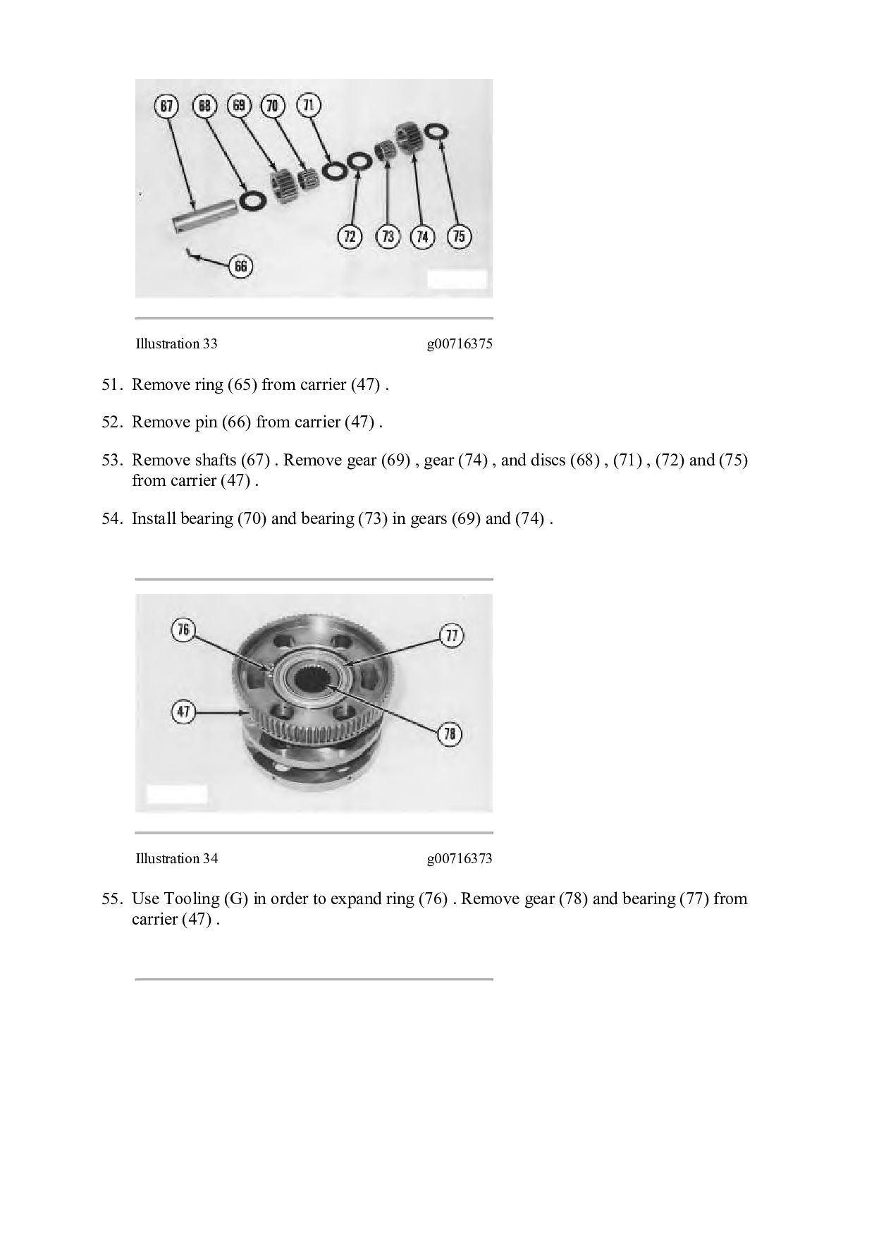
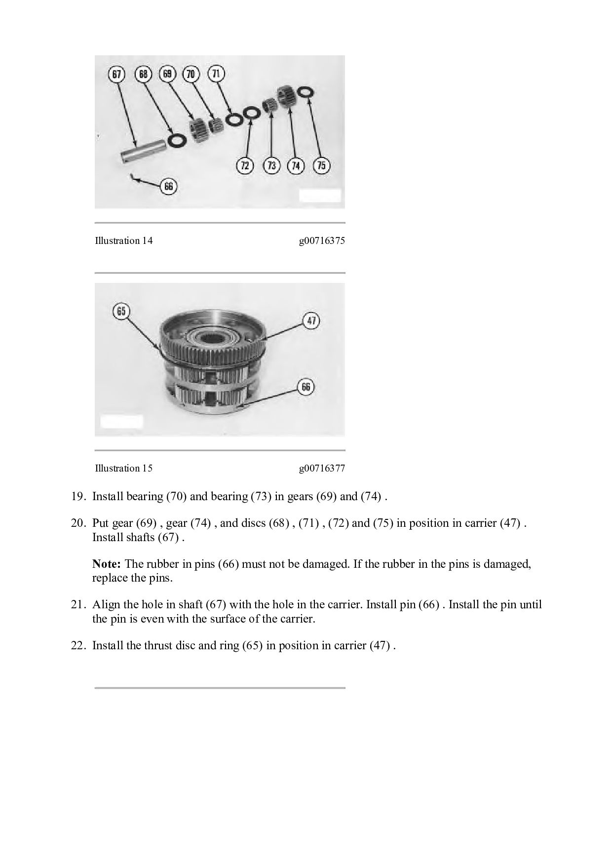
    and bearing (73) in gears (69) and (74) . 20. Put gear (69) , gear (74) , and discs (68) , (71) , (72) and (75) in position in carrier (47) . Install shafts (67) . Note: The rubber in pins (66) must not be damaged. If the rubber in the pins is damaged, replace the pins. 21. Align the hole in shaft (67) with the hole in the carrier. Install pin (66) . Install the pin until the pin is even with the surface of the carrier. 22. Install the thrust disc and ring (65) in position in carrier (47) .
  29. Illustration 16 g00716379 23. Compress the ring in carrier (47)

    . Install the carrier in gear (64) . 24. Install carrier (47) and the gear as an assembly. Illustration 17 g00716382 25. Use Tooling (G) in order to install snap ring (63) . Illustration 18 g00716385
  30. Note: Bottom plate of plates (62) must be turned over

    to allow the clutch springs to put pressure on the bottom plate at location (X) . Note: Start with a plate, alternate discs, and plates. Continue to alternate until all the discs and the plates have been installed. 26. Install plates (62) and discs (61) . Illustration 19 g00716729 27. Put plates (59) in position on the housing. 28. Install gear (60) . Illustration 20 g00716731 29. Install rings (102) and (103) on piston (55) with the lip of the rings upward, as shown. Put clean SAE 30 oil on the rings.
  31. Illustration 21 g00716732 Illustration 22 g00716734 30. Install rods (54)

    and springs (56) . Springs (56) must be in position on the bottom plate of plates (62) . Note: The top plate of plates (58) must be installed so that the small hole in the large tabs is aligned with rods (54) . Start with a plate, alternate discs, and plates. Continue to alternate until all the discs and the plates have been installed. 31. Install discs (57) and plates (58) . 32. Install piston (55) in housing (52) . 33. Put housing (52) in position on plate (59) .
  32. Illustration 23 g00716737 34. Install bolts (53) in order to

    hold housing (52) in place. Illustration 24 g00716738 Illustration 25 g00716739 35. Use Tooling (H) in order to install bearings (104) and (105) in shaft (48) . Install bearing (104) until the bearing is 10 mm ± 0.05 mm (0.39 inch ± 0.002 inch) below the end of the shaft. Install bearing (105) until the bearing is 15 mm ± 0.05 mm (0.59 inch ± 0.002 inch)
  33. below the end of the shaft. The inside diameter of

    the bearings must be 39.653 mm ± 0.039 mm (1.5611 inch ± 0.0015 inch) after installation. Illustration 26 g00716741 36. Align the notch in the inside race of bearing (51) with the dowel in shaft (48) . Install the bearing. 37. Put gear (50) in position on the shaft. Use Tool (F) in order to install snap ring (49) . Illustration 27 g00716743 38. Put shaft (48) in position in the planetary group.
  34. Illustration 28 g00716745 39. Install snap ring (46) in order

    to hold the shaft and the bearing in position in carrier (47) . Illustration 29 g00716747 40. Install the bearings in gears (45) . 41. Put gears (45) and discs (43) in position in carrier (37) . Install shafts (42) . Note: The rubber in pins (44) must not be damaged. If the rubber is damaged, replace the pins. 42. Align the hole in shaft (42) with the hole in the carrier. Install pin (44) . Install the pin until the pin is even with the surface of the carrier. 43. Install ring (41) . 44. Put ring (40) in position in the carrier.
  35. Thank you very much for your reading. Please Click Here.

    Then Get COMPLETE MANUAL. NO WAITING NOTE: If there is no response to click on the link above, please download the PDF document first and then click on it.
  36. Illustration 30 g00716748 45. Compress the ring in carrier (37)

    . Install the carrier in gear (38) . 46. Put the carrier and gear (38) in position on the transmission. Illustration 31 g00716749 47. Install rings (106) and (107) on piston (33) . Install the rings with the lip upward, as shown. Put clean oil on the rings.
  37. Illustration 32 g00716752 Illustration 33 g00716758 48. Put springs (35)

    in position on rods (54) . Note: The top plate of plates (34) must be installed so that the small hole in the large tabs is aligned with rods (54) . Start with a plate, alternate discs, and plates. Continue to alternate until all the discs and plates have been installed. 49. Install discs (36) and plates (34) . 50. Install piston (33) in housing assembly (32) . 51. Put housing assembly (32) in position on the transmission. Illustration 34 g00716763 52. Put plate (30) in position on gear (13) . Install ring (31) .
  38. Illustration 35 g00716771 53. Put gear (13) in position in

    the transmission, as shown. Illustration 36 g00716780 54. Put gear (28) in position on the shaft. Use Tooling (F) in order to install snap ring (29) . Illustration 37 g00716790
  39. https://www.aservicemanualpdf.com/ My Dear Friend! Thank you very much for visiting.

    Full manual if required, please enter the following URL into your browser. https://www.aservicemanualpdf.com/