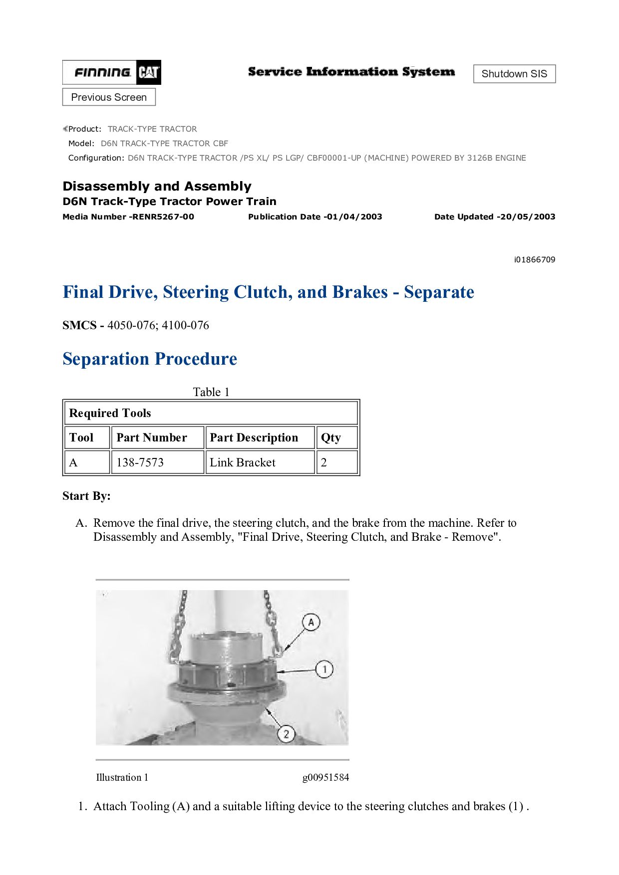
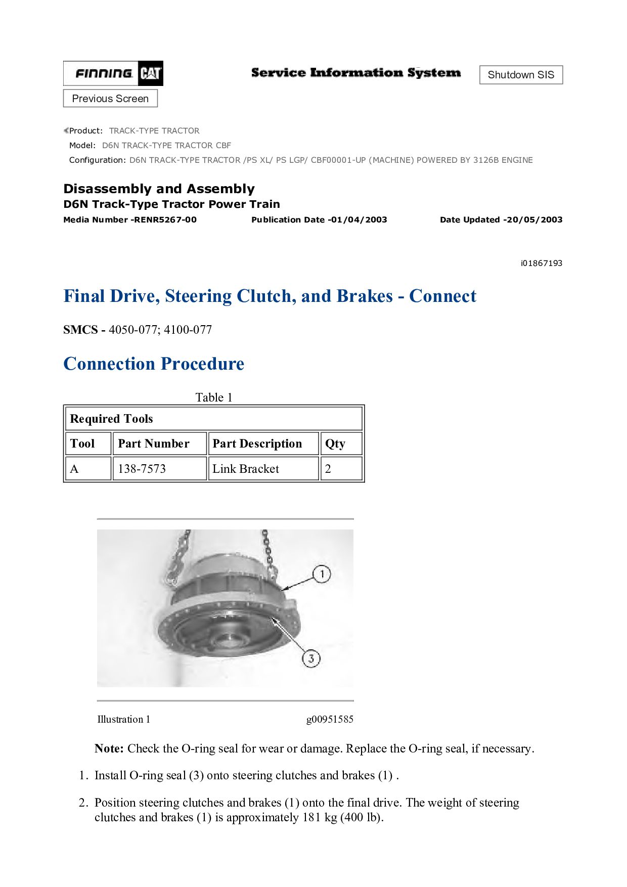
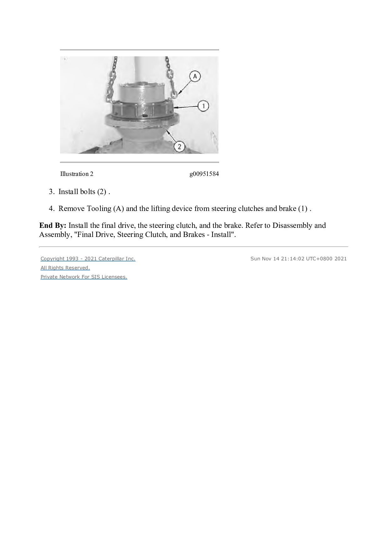
TRACTOR CBF Configuration: D6N TRACK-TYPE TRACTOR /PS XL/ PS LGP/ CBF00001-UP (MACHINE) POWERED BY 3126B ENGINE Disassembly and Assembly D6N Track-Type Tractor Power Train Media Number -RENR5267-00 Publication Date -01/04/2003 Date Updated -20/05/2003 i01866709 Final Drive, Steering Clutch, and Brakes - Separate SMCS - 4050-076; 4100-076 Separation Procedure Table 1 Required Tools Tool Part Number Part Description Qty A 138-7573 Link Bracket 2 Start By: A. Remove the final drive, the steering clutch, and the brake from the machine. Refer to Disassembly and Assembly, "Final Drive, Steering Clutch, and Brake - Remove". Illustration 1 g00951584 1. Attach Tooling (A) and a suitable lifting device to the steering clutches and brakes (1) .
![Please write to us. Our email: [email protected] Please go to](https://files.speakerdeck.com/presentations/baaaa95e514f481d93f8202f60bc9039/slide_29.jpg)