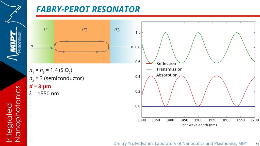
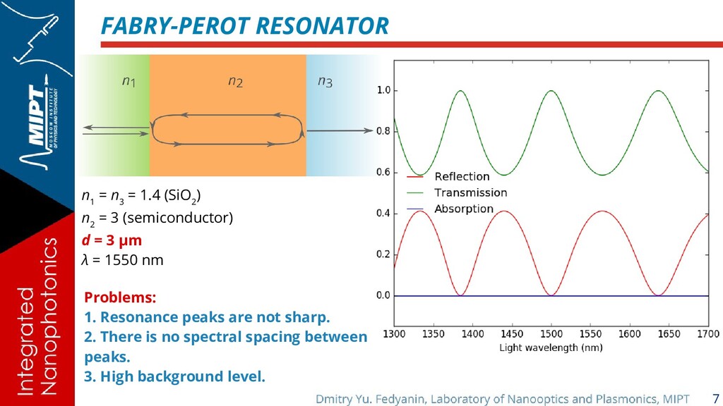
(SiO 2 ) n 2 = 3 (semiconductor) d = 3 μm λ = 1550 nm Problems: 1. Resonance peaks are not sharp. 2. There is no spectral spacing between peaks. 3. High background level.
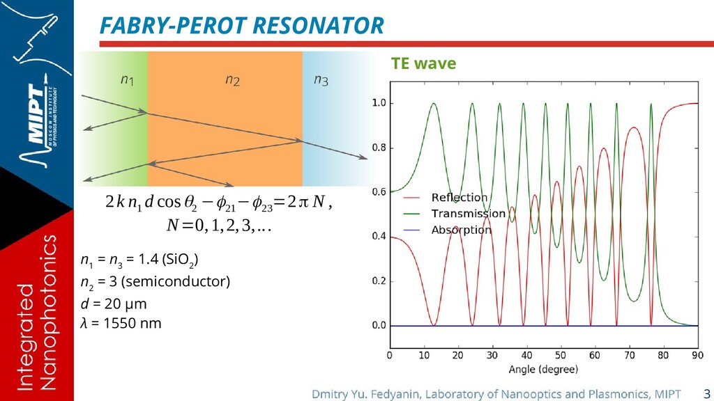
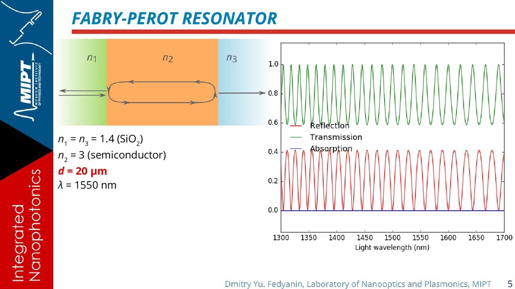
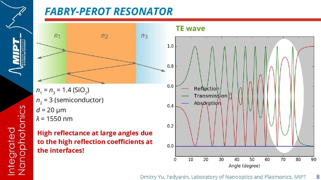
= 1.4 (SiO 2 ) n 2 = 3 (semiconductor) d = 20 μm λ = 1550 nm High reflectance at large angles due to the high reflection coefficients at the interfaces!
(SiO 2 ) n 2 = 3 (semiconductor) d = 3 μm λ = 1550 nm Problems: 1. Resonance peaks are not sharp. 2. There is no spectral spacing between peaks. 3. High background level.
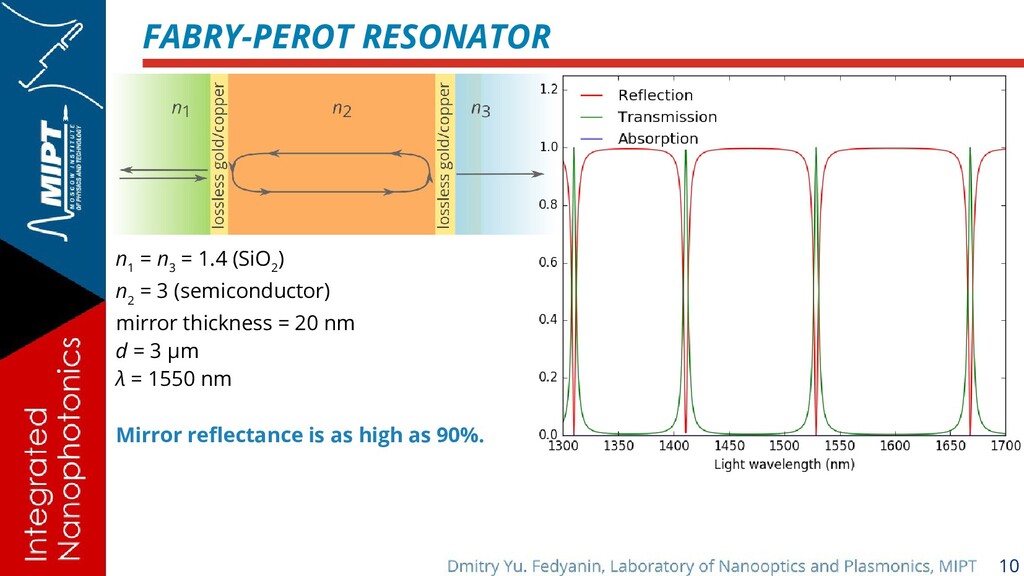
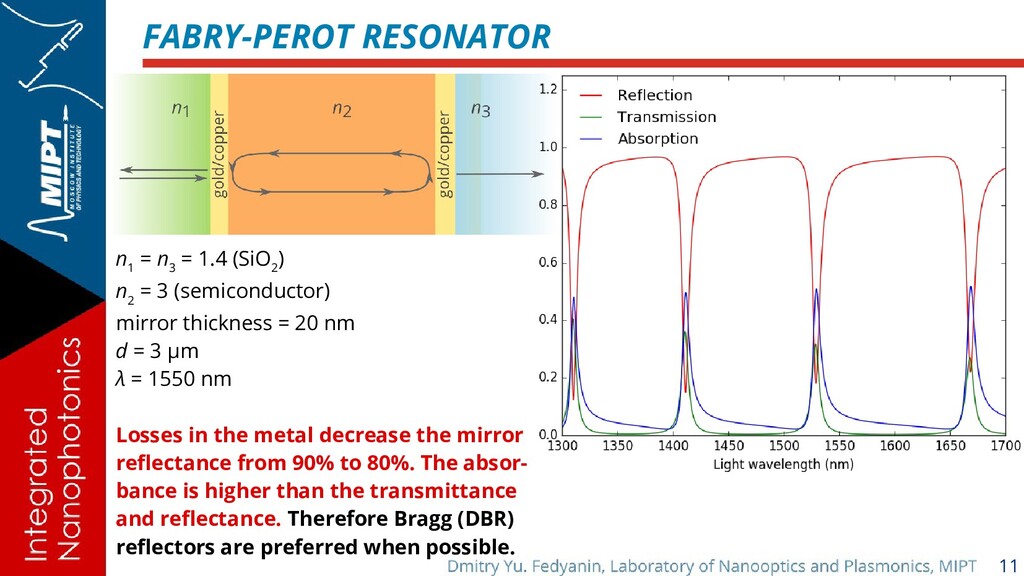
(SiO 2 ) n 2 = 3 (semiconductor) mirror thickness = 20 nm d = 3 μm λ = 1550 nm Losses in the metal decrease the mirror reflectance from 90% to 80%. The absor- bance is higher than the transmittance and reflectance. Therefore Bragg (DBR) reflectors are preferred when possible.
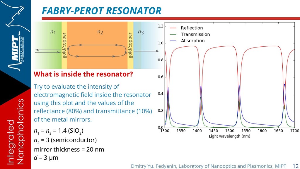
evaluate the intensity of electromagnetic field inside the resonator using this plot and the values of the reflectance (80%) and transmittance (10%) of the metal mirrors. n 1 = n 3 = 1.4 (SiO 2 ) n 2 = 3 (semiconductor) mirror thickness = 20 nm d = 3 μm
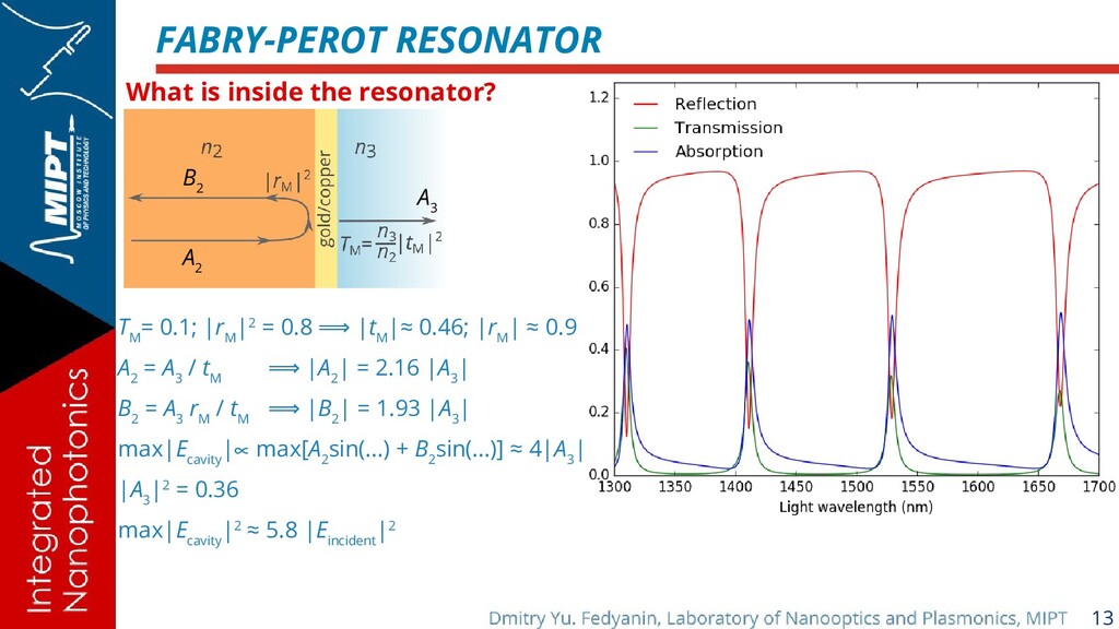
B 2 A 3 T M = 0.1; |r M |2 = 0.8 | ⟹ t M |≈ 0.46; |r M | ≈ 0.9 A 2 = A 3 / t M | ⟹ A 2 | = 2.16 |A 3 | B 2 = A 3 r M / t M | ⟹ B 2 | = 1.93 |A 3 | max|E cavity | max[ ∝ A 2 sin(...) + B 2 sin(...)] ≈ 4|A 3 | |A 3 |2 = 0.36 max|E cavity |2 ≈ 5.8 |E incident |2
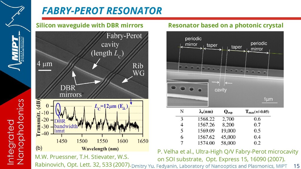
T.H. Stievater, W.S. Rabinovich, Opt. Lett. 32, 533 (2007). Resonator based on a photonic crystal P. Velha et al., Ultra-High Q/V Fabry-Perot microcavity on SOI substrate, Opt. Express 15, 16090 (2007).
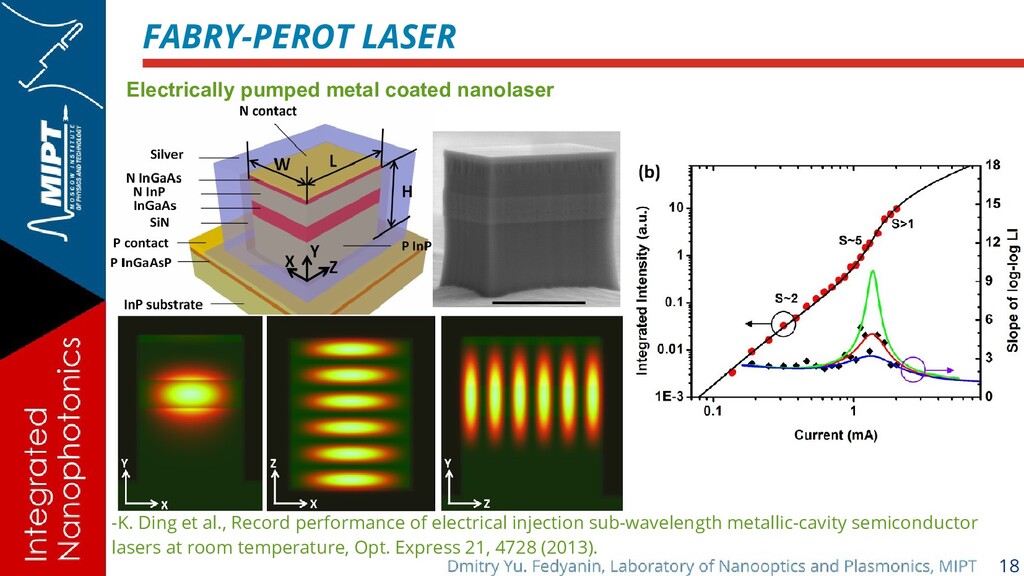
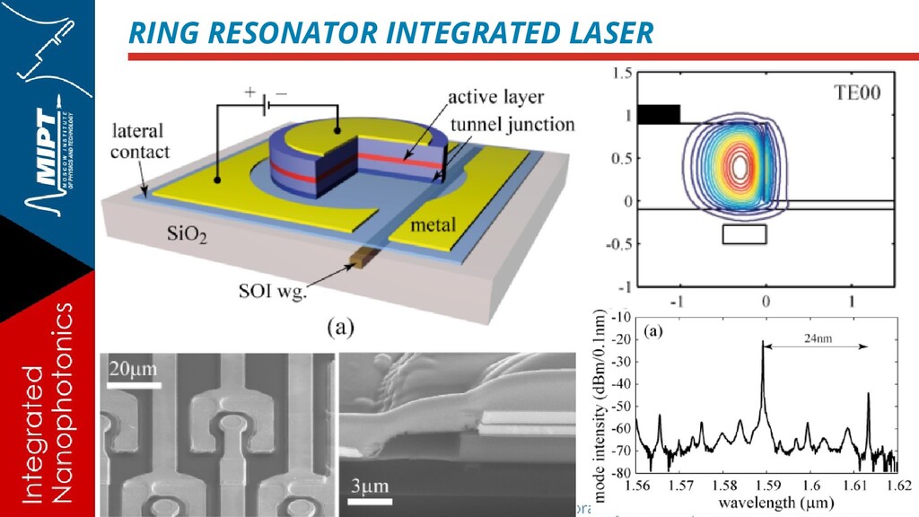
et al., Record performance of electrical injection sub-wavelength metallic-cavity semiconductor lasers at room temperature, Opt. Express 21, 4728 (2013).
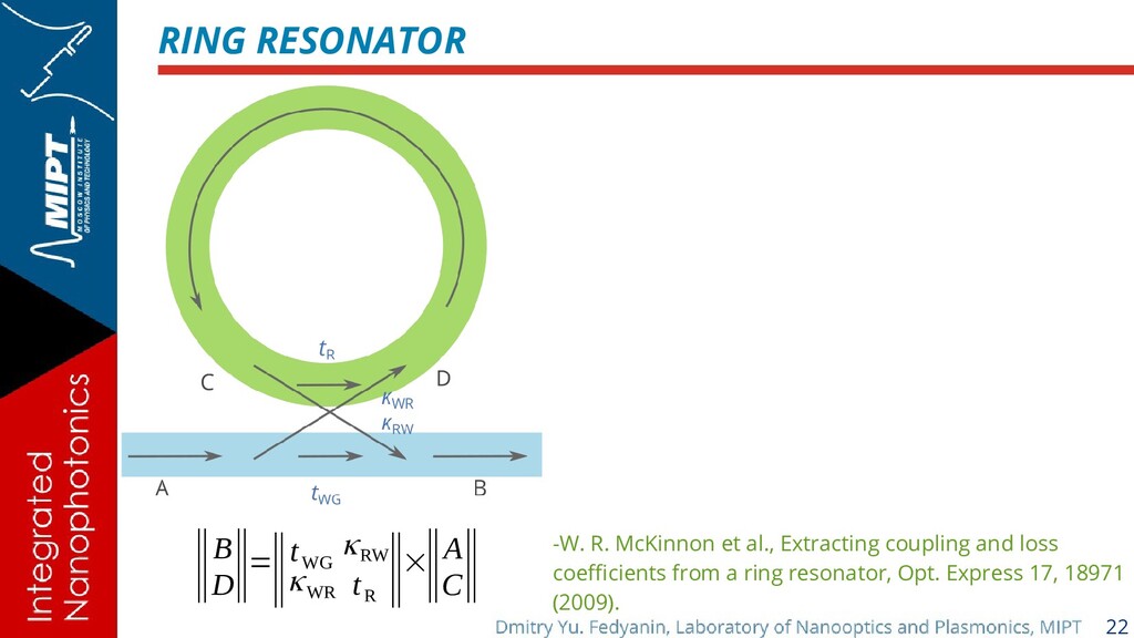
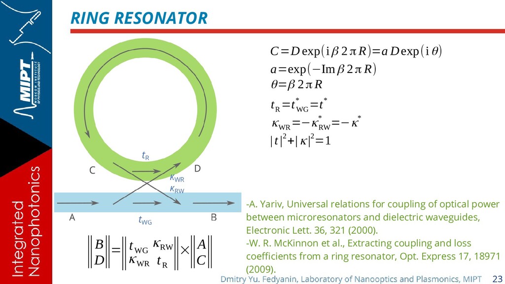
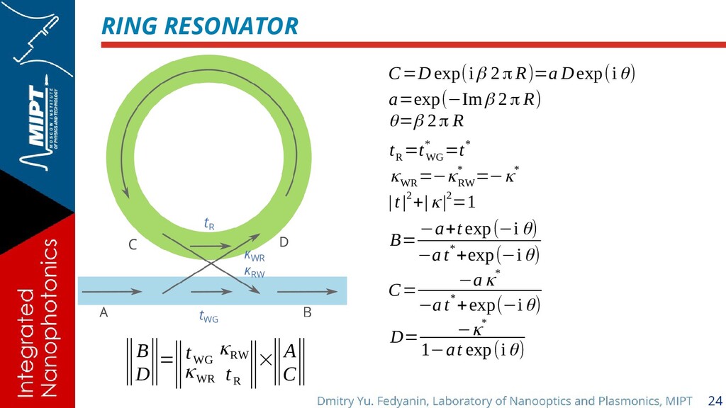
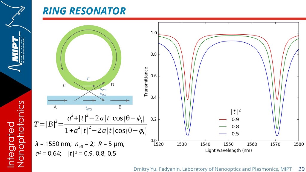
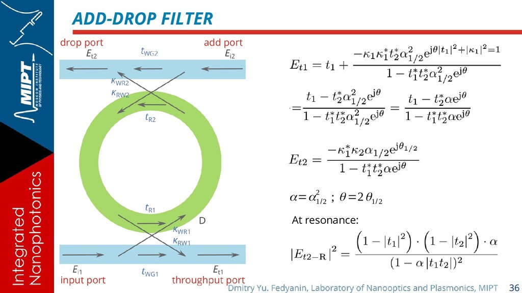
R ‖×‖A C ‖ C=D exp(iβ 2π R)=a Dexp(iθ) a=exp(−Imβ 2π R) θ=β 2π R t R =t WG * =t* κWR =−κRW * =−κ* |t |2 +| κ|2 =1 -A. Yariv, Universal relations for coupling of optical power between microresonators and dielectric waveguides, Electronic Lett. 36, 321 (2000). -W. R. McKinnon et al., Extracting coupling and loss coefficients from a ring resonator, Opt. Express 17, 18971 (2009).
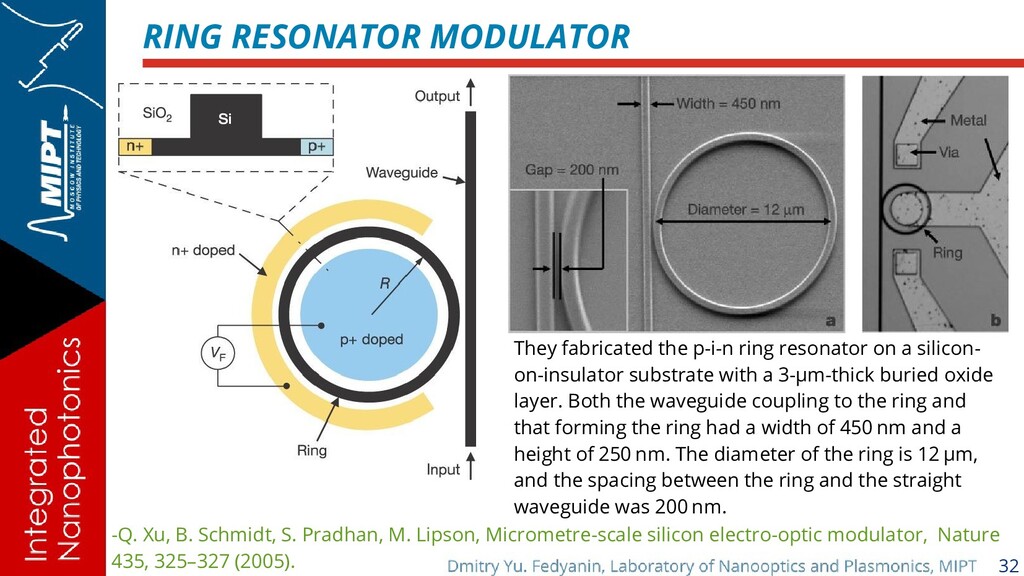
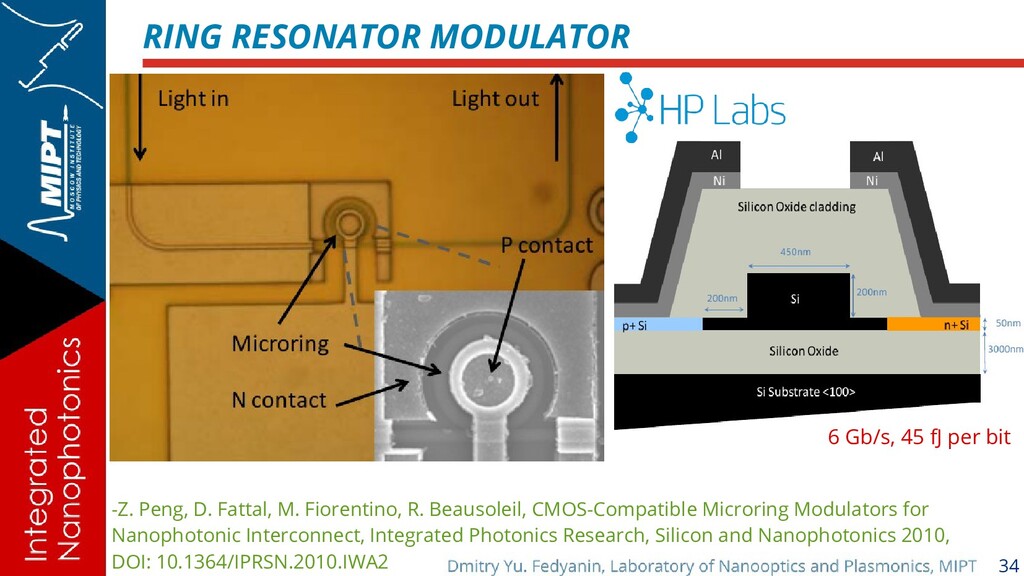
M. Lipson, Micrometre-scale silicon electro-optic modulator, Nature 435, 325–327 (2005). They fabricated the p-i-n ring resonator on a silicon- on-insulator substrate with a 3-µm-thick buried oxide layer. Both the waveguide coupling to the ring and that forming the ring had a width of 450 nm and a height of 250 nm. The diameter of the ring is 12 µm, and the spacing between the ring and the straight waveguide was 200 nm.
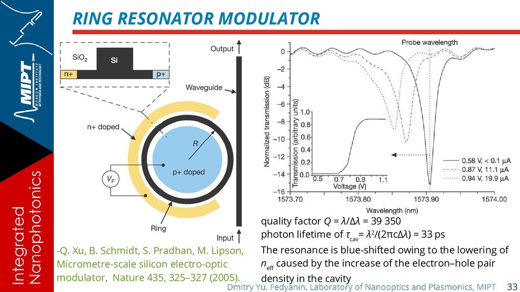
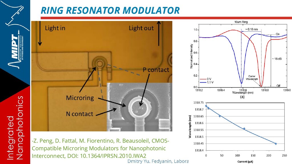
M. Lipson, Micrometre-scale silicon electro-optic modulator, Nature 435, 325–327 (2005). quality factor Q = λ/Δλ = 39 350 photon lifetime of τ cav = λ2/(2πcΔλ) = 33 ps The resonance is blue-shifted owing to the lowering of n eff caused by the increase of the electron–hole pair density in the cavity
R. Beausoleil, CMOS-Compatible Microring Modulators for Nanophotonic Interconnect, Integrated Photonics Research, Silicon and Nanophotonics 2010, DOI: 10.1364/IPRSN.2010.IWA2 6 Gb/s, 45 fJ per bit
Homework: Article mentioned in the presentation D. G. Rabus, Integrated Ring Resonators: The Compendium, Springer Series in Optical Sciences, Springer, 2007. Chapter 2 S. L. Chuang, Physics of Photonic Devices, Wiley, 2009. Section 8.4