Upgrade to Pro — share decks privately, control downloads, hide ads and more …

Marvels of Memory Auto-configuration (also know...

Marvels of Memory Auto-configuration (also known as SPD)

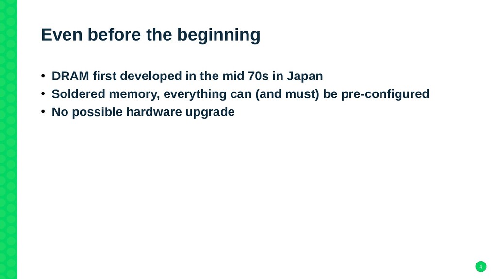
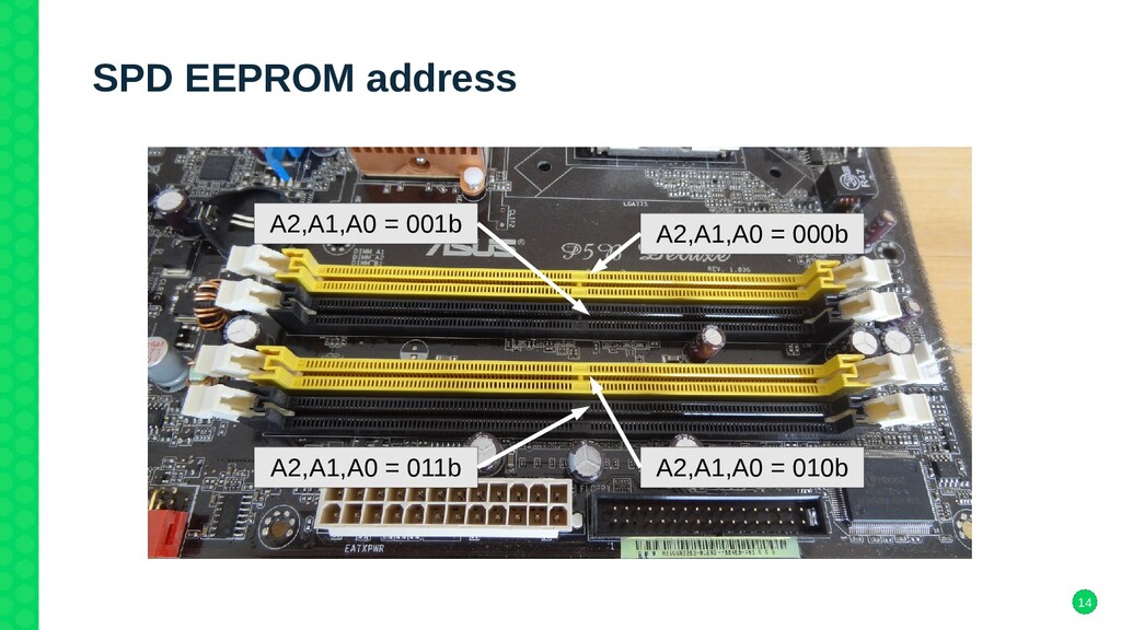
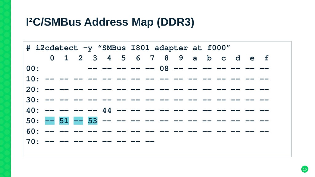
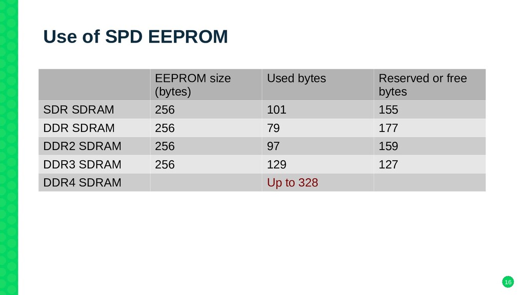
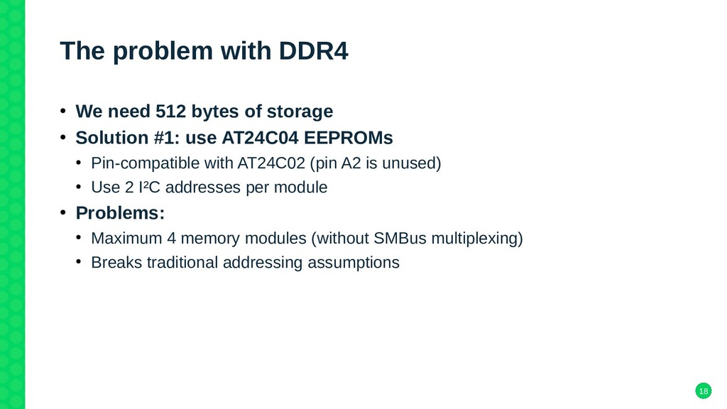
System memory configuration is a transparent operation nowadays, something that we all came to expect to just work out of the box. Still, it does happen behind the scenes every single time we boot our computers. This requires the cooperation of hardware components on the mainboard and on memory modules themselves, as well as firmware code to drive these. While it is possible to just let it happen, having a deeper understanding of how it works makes it possible to access valuable information from the operating system at run-time.

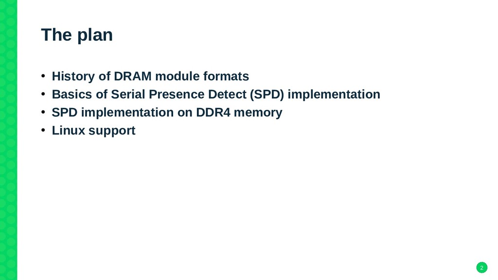
I will take you through the history of system memory configuration from the mid 70s to now. We will explore the different types of memory modules, how their configuration data is stored and how the firmware can access them. We will see which problems had to be solved along the way and how they were solved. Lastly we will see how Linux suports reading the memory configuration information and what you can do with that information.

Jean Delvare, SUSE

Kernel Recipes

December 22, 2021
Tweet

More Decks by Kernel Recipes

Other Decks in Technology

Transcript

  1. 2 The plan • History of DRAM module formats •

    Basics of Serial Presence Detect (SPD) implementation • SPD implementation on DDR4 memory • Linux support
  2. 4 Even before the beginning • DRAM first developed in

    the mid 70s in Japan • Soldered memory, everything can (and must) be pre-configured • No possible hardware upgrade
  3. 5 In the (x86) beginning • 30-pin SIMM on 286

    to 486 (80s) • No room for configuration information • Hardware probing at every boot, or manual configuration • Limited upgrade options
  4. 6 Then there was PPD (Parallel Presence Detect) • 72-pin

    SIMM on 486 to early Pentium® II (90s) • 4 pins used for configuration data • 2 for memory module size • 2 for memory access time Pin Name Description (...) 67 PD1 Presence Detect 1 68 PD2 Presence Detect 2 69 PD3 Presence Detect 3 70 PD4 Presence Detect 4 (...)
  5. 7 Parallel Presence Detect (PPD) • Quickly limited by the

    low number of pins • How do you express sizes of 1, 2, 4, 8, 16, 32 and 64 MB with only 2 bits? • How do you express access times of 100, 80, 70, 60 and 50 ns with only 2 bits? • Well, you don’t! • Hardware probing or manual configuration still needed PD2 PD1 Size (MB) GND GND 4 or 64 GND NC 2 or 32 NC GND 1 or 16 NC NC 8 PD4 PD3 Access time (ns) GND GND 50 or 100 GND NC 80 NC GND 70 NC NC 60
  6. 8 Parallel Presence Detect (cont’d) • Later revisions added a

    5th, then 6th and 7th pin to handle ECC and larger module sizes • Doesn’t solve the problem • Doesn’t scale • Needs for finer-grained timings (beyond access time) • Hardware probing or manual configuration is going to be a disaster
  7. 9 Then there was SPD (Serial Presence Detect) • SIMM

    replaced by 168-pin DIMM in the mid 90s (Pentium®) • PPD replaced by SPD • 5 pins used for configuration data Pin Name Description (...) 82 SDA Serial Data 63 SCL Serial Clock (...) 123 SA0 Serial Address bit 0 124 SA1 Serial Address bit 1 125 SA2 Serial Address bit 2 (...)
  8. 11 Serial Presence Detect (SPD) • Fixed number of pins

    • Independent of the amount of configuration data to be stored • No hardware probing or manual configuration needed • 3 address pins allow connecting up to 8 modules to the same serial bus • Reduced board footprint compared to PPD • Data stored in AT24C02 EEPROMs • Standard and cheap • I²C and SMBus compatible • Up to 256 bytes of data for memory type, size, timings, and more
  9. 12 SMBus diagram 2 wires: Serial Clock (SCL) Serial Data

    (SDA) SMBus controller DIMM Slot DIMM Slot DIMM Slot DIMM Slot Hardware monitor
  10. 13 SPD EEPROM pinout SPD EEPROM (AT24C02) Vcc A0 NC

    SCL SDA A1 A2 Vss In red: connected to the memory module (power) In blue: connected to the SMBus through the memory slot (data) In black: connected directly to the memory slot (address) Full I²C address is: 1010(A2)(A1)(A0)b = 0x50-0x57
  11. 15 I²C/SMBus Address Map (DDR3) # i2cdetect -y “SMBus I801

    adapter at f000” 0 1 2 3 4 5 6 7 8 9 a b c d e f 00: -- -- -- -- -- 08 -- -- -- -- -- -- -- 10: -- -- -- -- -- -- -- -- -- -- -- -- -- -- -- -- 20: -- -- -- -- -- -- -- -- -- -- -- -- -- -- -- -- 30: -- -- -- -- -- -- -- -- -- -- -- -- -- -- -- -- 40: -- -- -- -- 44 -- -- -- -- -- -- -- -- -- -- -- 50: -- 51 -- 53 -- -- -- -- -- -- -- -- -- -- -- -- 60: -- -- -- -- -- -- -- -- -- -- -- -- -- -- -- -- 70: -- -- -- -- -- -- -- --
  12. 16 Use of SPD EEPROM EEPROM size (bytes) Used bytes

    Reserved or free bytes SDR SDRAM 256 101 155 DDR SDRAM 256 79 177 DDR2 SDRAM 256 97 159 DDR3 SDRAM 256 129 127 DDR4 SDRAM Up to 328
  13. 18 The problem with DDR4 • We need 512 bytes

    of storage • Solution #1: use AT24C04 EEPROMs • Pin-compatible with AT24C02 (pin A2 is unused) • Use 2 I²C addresses per module • Problems: • Maximum 4 memory modules (without SMBus multiplexing) • Breaks traditional addressing assumptions
  14. 19 I²C/SMBus Address Map (using AT24C04) 0 1 2 3

    4 5 6 7 8 9 a b c d e f 00: -- -- -- -- -- 08 -- -- -- -- -- -- -- 10: -- -- -- -- -- -- -- -- -- -- -- -- -- -- -- -- 20: -- -- -- -- -- -- -- -- -- -- -- -- -- -- -- -- 30: -- -- -- -- -- -- -- -- -- -- -- -- -- -- -- -- 40: -- -- -- -- 44 -- -- -- -- -- -- -- -- -- -- -- 50: 50 51 52 53 -- -- -- -- -- -- -- -- -- -- -- -- 60: -- -- -- -- -- -- -- -- -- -- -- -- -- -- -- -- 70: -- -- -- -- -- -- -- -- Slot #1 Slot #2 Slot #3 Slot #4
  15. 20 The problem with DDR4 (cont’d) • Solution #2: use

    AT24C32 EEPROMs • Pin-compatible with AT24C02 • Use 1 I²C address per module, maximum 8 modules, respect traditional addressing assumptions • Offer more capacity than we will ever need (4096 bytes) • Problem: • Use 2-byte addressing – not compatible with SMBus!
  16. 21 Reading from EEPROMs 1-byte addressing (SMBus-compatible) 2-byte addressing (not

    SMBus-compatible) S I²C addr data addr S I²C addr data S A A A A W R ... A Master to slave Slave to master S I²C addr data addr 1 S I²C addr data A A A A W R Master to slave Slave to master data addr 2 A ...
  17. 22 The Jedec solution for DDR4 • Solution #3: define

    a new EEPROM standard that uses paging • Named EE1004 • Pin-compatible with AT24C02 • Uses 1 main I²C address per module, maximum 8 modules, respects traditional addressing assumptions • Implements block write protection in a standard way • Uses extra I²C addresses for page selection, page querying, and write protection
  18. 23 I²C/SMBus Address Map (DDR4) # i2cdetect -y “SMBus I801

    adapter at f000” 0 1 2 3 4 5 6 7 8 9 a b c d e f 00: -- -- -- -- -- 08 -- -- -- -- -- -- -- 10: -- -- -- -- 14 15 -- -- -- -- -- -- -- -- -- -- 20: -- -- -- -- -- -- -- -- -- -- -- -- -- -- -- -- 30: 30 31 32 -- 34 35 -- -- -- -- -- -- -- -- -- -- 40: -- -- -- -- 44 -- -- -- -- -- -- -- -- -- -- -- 50: -- 51 -- 53 -- -- -- -- -- -- -- -- -- -- -- -- 60: -- -- -- -- -- -- -- -- -- -- -- -- -- -- -- -- 70: -- 71 -- -- -- -- -- --
  19. 24 DDR4-specific I²C addresses • 0x31, 0x34, 0x35, 0x30: Query

    or set write protection (per block) • 0x33: Clear write protection (all blocks) • 0x36, 0x37: Query or select page 1 page (256 bytes) = 2 blocks All these addresses are shared by all installed memory modules
  20. 25 The Jedec solution for DDR4 (cont’d) • Uses broadcast

    messages for everything • Fast but fragile • Abuses the I²C protocol (validation, arbitration) • Hardly extendable • 7 out of 8 control addresses already consumed • No provision for larger variants • Includes useless payload in messages for no good reason • My advice to Jedec engineers: KISS
  21. 26 DDR4 example: Select page 0 What DIMM#1 answers: What

    DIMM#2 answers: What the SMBus master sees: → Can’t be sure that page selection worked on all DIMMs S 0x36 dummy S A A A W dummy S 0x36 dummy S N N N W dummy S 0x36 dummy S A A A W dummy
  22. 27 DDR4 example: Page querying What DIMM#1 answers (page 0

    is selected): What DIMM#2 answers (page 1 is selected): What the SMBus master sees: page 0 is selected → Can’t be sure that all DIMMs are on the same page S 0x36 dummy S A A A R dummy S 0x36 dummy S N N N R dummy S 0x36 dummy S A A A R dummy
  23. 29 Do we need it? • Not mandatory • Good

    to have for: • Diagnostics (detecting sub-optimal memory module pairing) • Inventory purposes • Adding memory to an existing system • Tools like dmidecode are not accurate enough
  24. 30 Drivers • First of all you need an SMBus

    controller driver • i2c-i801 for recent Intel chipsets • i2c-piix4 for very old Intel chipsets and recent AMD chipsets • Many other drivers available in the kernel tree, look in drivers/i2c/busses. • Driver to read the EEPROMs themselves • eeprom (since lm_sensors project, December 1998, Philip Edelbrock; in kernel tree since v2.6.0, September 2003, thanks Greg KH) up to DDR3 • at24 (in kernel tree since v2.6.27, July 2008, Wolfram Sang) up to DDR3 • ee1004 (in kernel tree since v4.20, October 2018, Jean Delvare) for DDR4
  25. 31 User-space tools • decode-dimms (part of i2c-tools) • Perl

    script • Supports SDR, DDR, DDR2, DDR3 (since 2008-2013) and DDR4 (since 2017) SDRAM • Plain text or HTML output
  26. 32 Remaining problems • The legacy eeprom driver causes trouble

    • Binds to all devices at compatible I²C address • Slow • Dangerous • Doesn’t work with DDR4 – even steals devices from ee1004 driver • Deprecated, must be removed altogether eventually • Both at24 and ee1004 require the EEPROM devices to be explicitly instantiated • Can be done automatically on DT/OF-based systems • But what about x86 desktops and servers? • ACPI?
  27. 33 Explicitly instantiating the EEPROMs Example of manual steps (for

    DDR3): # modprobe i2c-dev # i2cdetect -l # i2cdetect -y 9 # echo spd 0x50 > /sys/bus/i2c/devices/i2c-9/new_device # echo spd 0x51 > /sys/bus/i2c/devices/i2c-9/new_device Tedious and error-prone: • Bus number depends on system, not even stable • I²C addresses depend on installed DIMMs • Device name depends on memory type (ee1004 for DDR4)
  28. 34 The final touch (work in progress) We want it

    to work out of the box in the most common cases • Use DMI data to find out memory type • White list of supported memory types • Skip if there are more than 4 memory slots (at least on desktop systems) • Fine-tuning possible based on DMI data (chassis type...) • Probe I²C address 0x50-0x53 on the SMBus • Needed because DMI information is not complete enough • Must be enabled explicitly in each SMBus controller driver • Skip if SMBus is multiplexed • Instantiate the appropriate device on responsive addresses
  29. 36 My solution for DDR4 (but it’s too late) •

    Use one I²C control address per memory module • 0x30 for the module at main address 0x50 • 0x31 for the module at main address 0x51 • etc. • Compatible with SMBus, pin-compatible with AT24C02, complies with addressing expectations • 256 control commands available for block protection, page selection and more – highly extendable