with CLIC E. Perez (CERN) CLIC Workshop, March 10, 2017 Material from this talk comes mostly from : • the FCC-ee MDI group - two-weeks workshop in January, lead to a new baseline for the IR - not implemented yet in the simulations shown here • the FCC-ee detector group • CLICdp-note-2017-001 and the CLIC CDR Thanks in particular to Nilou Alipour, Nicola Baccheta, Manuela Boscolo, Konrad Elsener, Patrick Janot, Emilia Leogrande, Lucie Linsen, Georgios Voutsinas
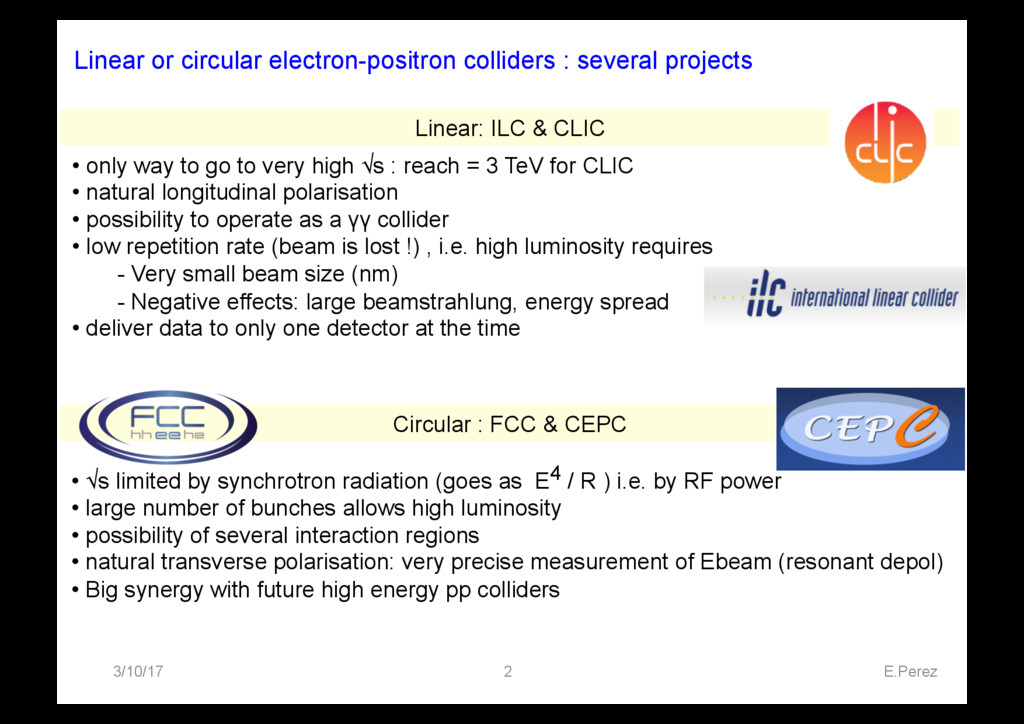
as E4 / R ) i.e. by RF power • large number of bunches allows high luminosity • possibility of several interaction regions • natural transverse polarisation: very precise measurement of Ebeam (resonant depol) • Big synergy with future high energy pp colliders • only way to go to very high √s : reach = 3 TeV for CLIC • natural longitudinal polarisation • possibility to operate as a γγ collider • low repetition rate (beam is lost !) , i.e. high luminosity requires - Very small beam size (nm) - Negative effects: large beamstrahlung, energy spread • deliver data to only one detector at the time Circular : FCC & CEPC Linear: ILC & CLIC Linear or circular electron-positron colliders : several projects
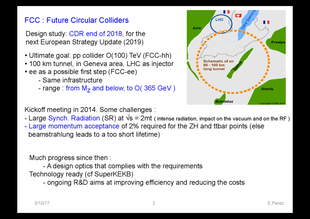
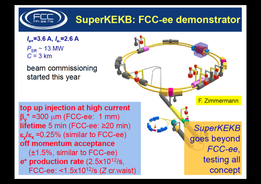
in 2014. Some challenges : - Large Synch. Radiation (SR) at √s = 2mt ( intense radiation, impact on the vacuum and on the RF ) - Large momentum acceptance of 2% required for the ZH and ttbar points (else beamstrahlung leads to a too short lifetime) Design study: CDR end of 2018, for the next European Strategy Update (2019) • Ultimate goal: pp collider O(100) TeV (FCC-hh) • 100 km tunnel, in Geneva area, LHC as injector • ee as a possible first step (FCC-ee) - Same infrastructure - range : from MZ and below, to O( 365 GeV ) Much progress since then : - A design optics that complies with the requirements Technology ready (cf SuperKEKB) - ongoing R&D aims at improving efficiency and reducing the costs
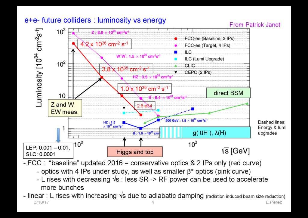
- FCC : “baseline” updated 2016 = conservative optics & 2 IPs only (red curve) - optics with 4 IPs under study, as well as smaller β* optics (pink curve) - L rises with decreasing √s : less SR -> RF power can be used to accelerate more bunches - linear : L rises with increasing √s due to adiabatic damping (radiation induced beam size reduction) Z and W EW meas. Higgs and top g( ttH ), λ(H) direct BSM Dashed lines: Energy & lumi upgrades LEP: 0.001 – 0.01, SLC: 0.0001 4.2 x 1036 cm-2 s-1 3.8 x 1035 cm-2 s-1 1.0 x 1035 cm-2 s-1 2.6 e34 From Patrick Janot
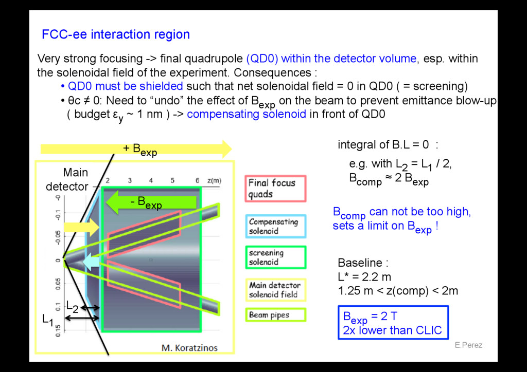
final quadrupole (QD0) within the detector volume, esp. within the solenoidal field of the experiment. Consequences : • QD0 must be shielded such that net solenoidal field = 0 in QD0 ( = screening) • θc ≠ 0: Need to “undo” the effect of Bexp on the beam to prevent emittance blow-up ( budget εy ~ 1 nm ) -> compensating solenoid in front of QD0 Baseline : L* = 2.2 m 1.25 m < z(comp) < 2m + Bexp - Bexp e.g. with L2 = L1 / 2, Bcomp ≈ 2 Bexp Bcomp can not be too high, sets a limit on Bexp ! Main detector Bexp = 2 T 2x lower than CLIC integral of B.L = 0 : L1 L2
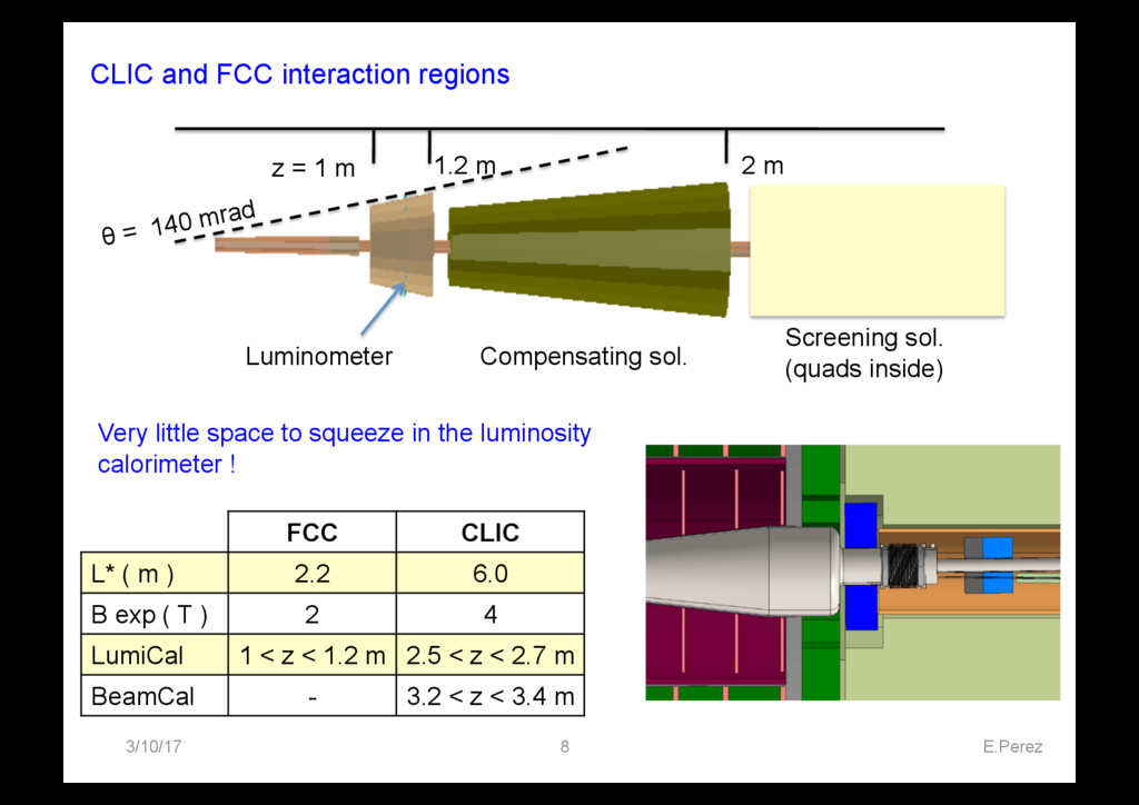
L* ( m ) 2.2 6.0 B exp ( T ) 2 4 LumiCal 1 < z < 1.2 m 2.5 < z < 2.7 m BeamCal - 3.2 < z < 3.4 m Compensating sol. Screening sol. (quads inside) Luminometer z = 1 m 1.2 m 2 m θ = 140 mrad Very little space to squeeze in the luminosity calorimeter !
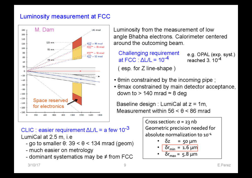
LumiCal at z = 1m, Measurement within 56 < θ < 86 mrad Luminosity from the measurement of low angle Bhabha electrons. Calorimeter centered around the outcoming beam. • θmin constrained by the incoming pipe ; • θmax constrained by main detector acceptance, down to > 140 mrad ≈ 8 deg Space reserved for electronics CLIC : easier requirement ΔL/L = a few 10-3 LumiCal at 2.5 m, i.e - go to smaller θ: 39 < θ < 134 mrad (geom) - much easier on metrology - dominant systematics may be ≠ from FCC Challenging requirement at FCC : ΔL/L = 10-4 M. Dam e.g. OPAL (exp. syst.) reached 3. 10-4 ( esp. for Z line-shape )
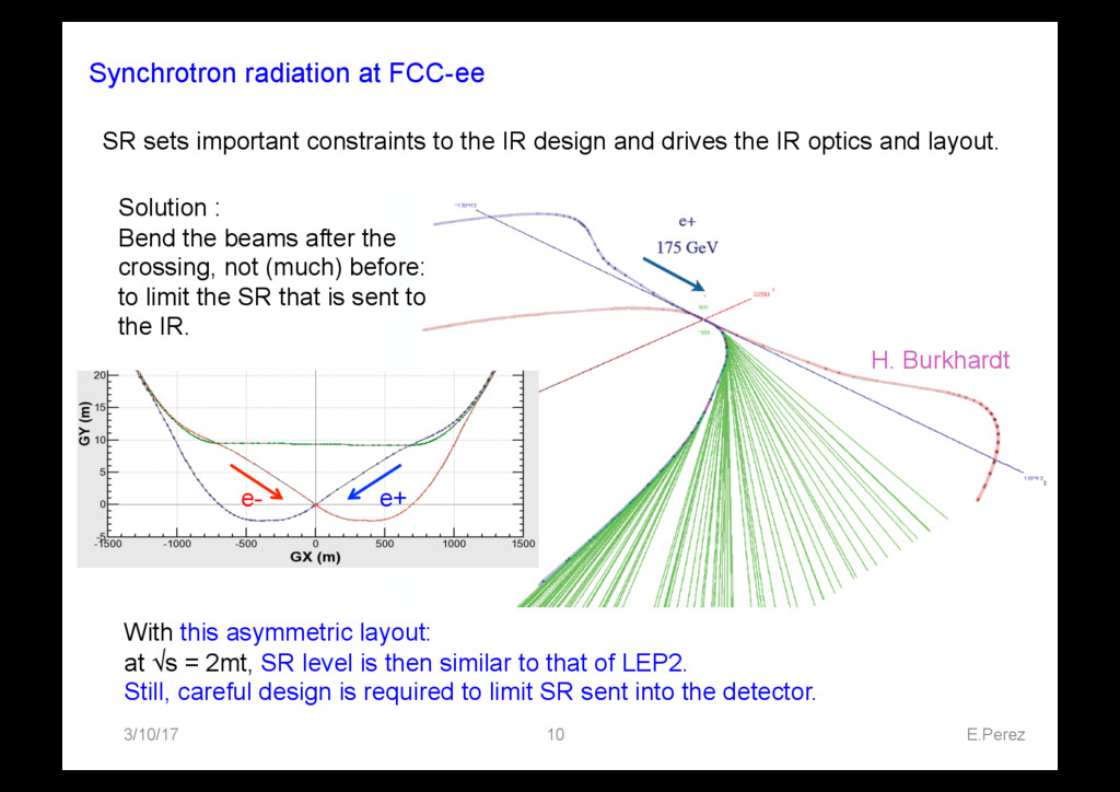
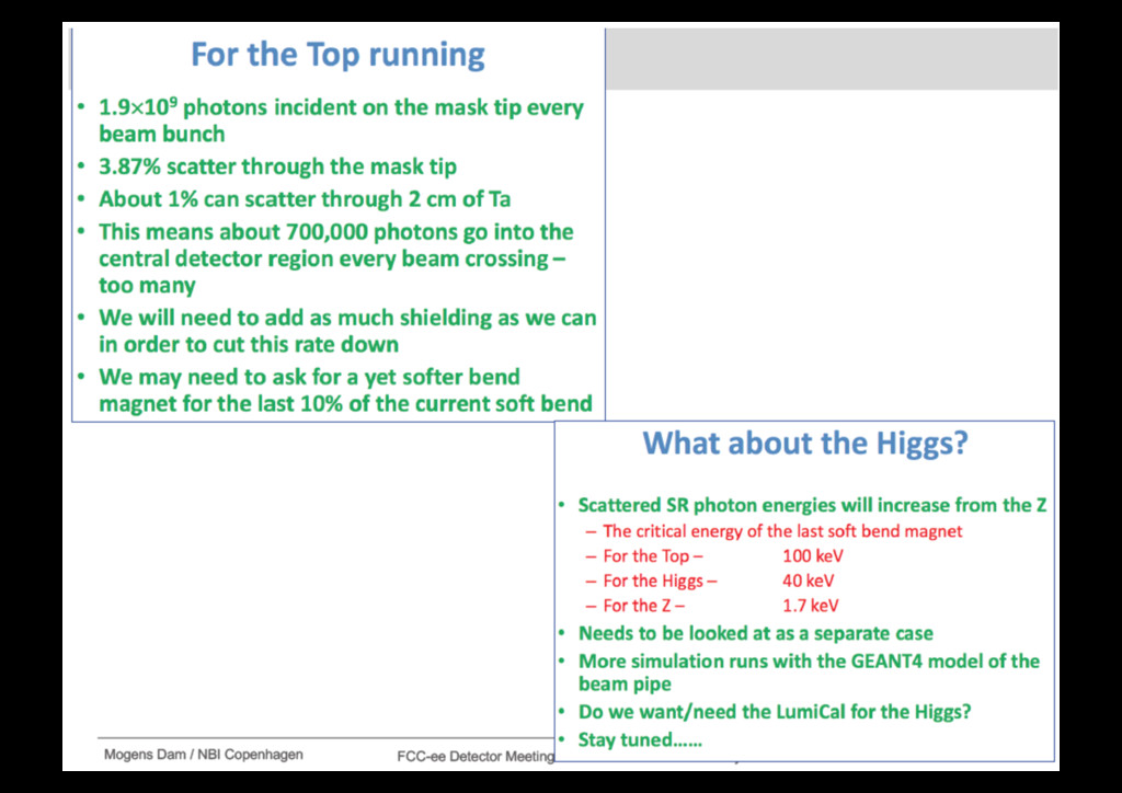
layout: at √s = 2mt, SR level is then similar to that of LEP2. Still, careful design is required to limit SR sent into the detector. SR sets important constraints to the IR design and drives the IR optics and layout. Solution : Bend the beams after the crossing, not (much) before: to limit the SR that is sent to the IR. - PSR < 1 kW within 250m of the IP - Eγ crit < 100 keV (minimize n prod.) H. Burkhardt e- e+
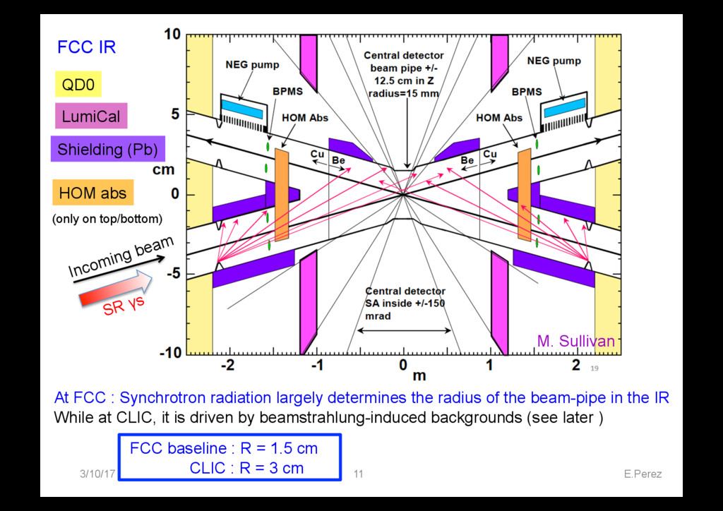
largely determines the radius of the beam-pipe in the IR While at CLIC, it is driven by beamstrahlung-induced backgrounds (see later ) FCC baseline : R = 1.5 cm CLIC : R = 3 cm QD0 LumiCal Incoming beam SR γs Shielding (Pb) HOM abs (only on top/bottom) M. Sullivan
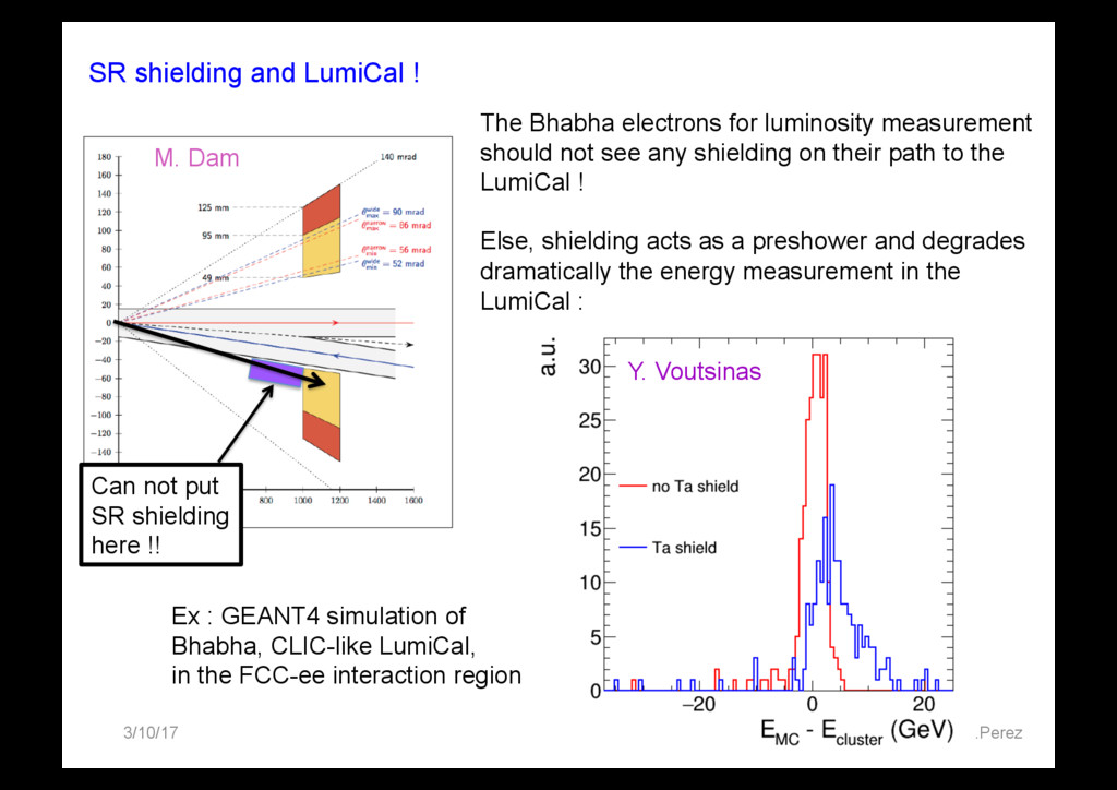
put SR shielding here !! The Bhabha electrons for luminosity measurement should not see any shielding on their path to the LumiCal ! Else, shielding acts as a preshower and degrades dramatically the energy measurement in the LumiCal : Ex : GEANT4 simulation of Bhabha, CLIC-like LumiCal, in the FCC-ee interaction region Y. Voutsinas M. Dam
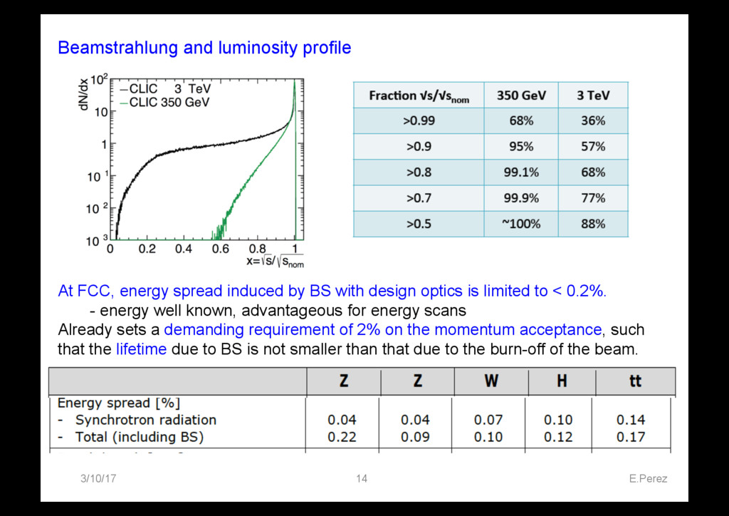
spread induced by BS with design optics is limited to < 0.2%. - energy well known, advantageous for energy scans Already sets a demanding requirement of 2% on the momentum acceptance, such that the lifetime due to BS is not smaller than that due to the burn-off of the beam.
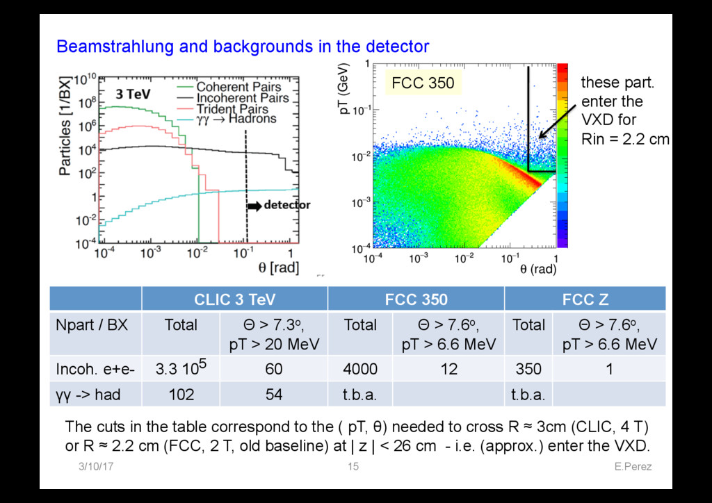
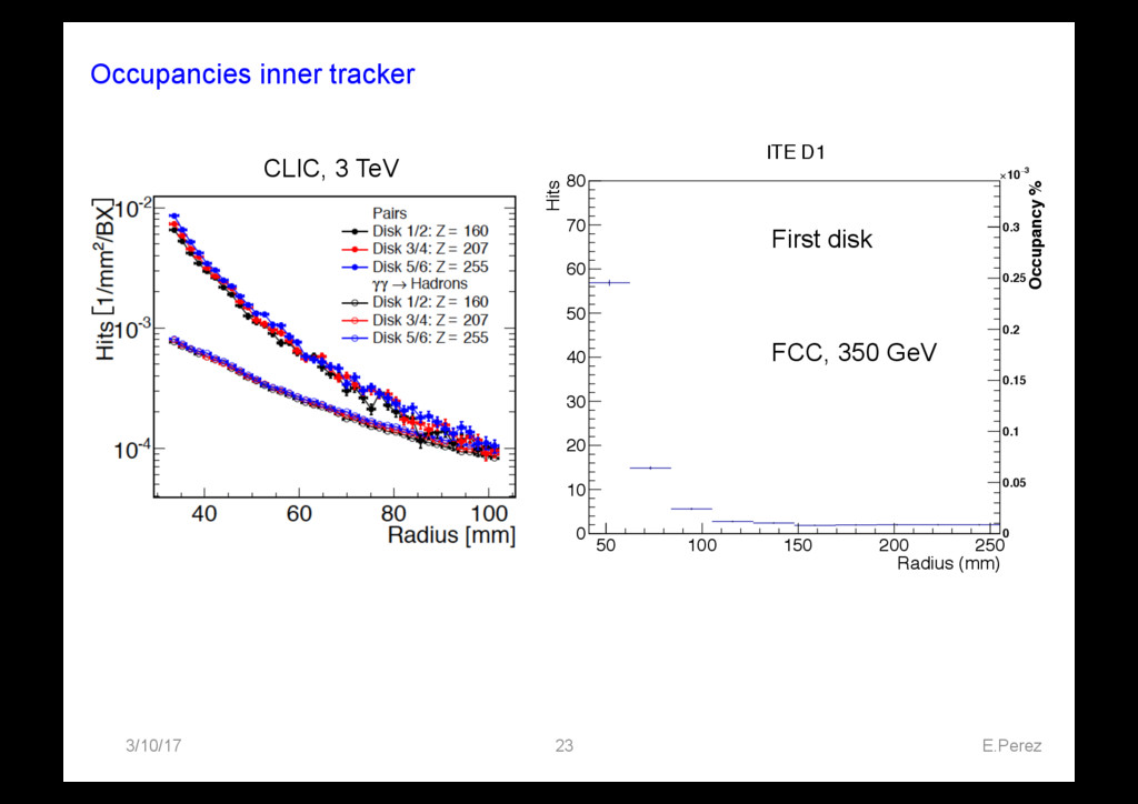
3 TeV FCC 350 FCC Z Npart / BX Total Θ > 7.3o, pT > 20 MeV Total Θ > 7.6o, pT > 6.6 MeV Total Θ > 7.6o, pT > 6.6 MeV Incoh. e+e- 3.3 105 60 4000 12 350 1 γγ -> had 102 54 t.b.a. t.b.a. The cuts in the table correspond to the ( pT, θ) needed to cross R ≈ 3cm (CLIC, 4 T) or R ≈ 2.2 cm (FCC, 2 T, old baseline) at | z | < 26 cm - i.e. (approx.) enter the VXD. FCC 350 these part. enter the VXD for Rin = 2.2 cm
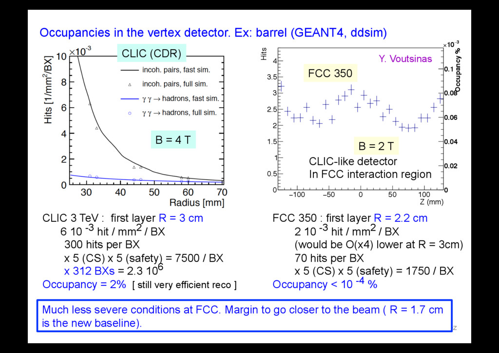
0 0.5 1 1.5 2 2.5 3 3.5 4 Occupancy % 0 0.02 0.04 0.06 0.08 0.1 3 ! 10 " VXD Barrel L1 Occupancies in the vertex detector. Ex: barrel (GEANT4, ddsim) 3/10/17 E.Perez 16 CLIC 3 TeV : first layer R = 3 cm 6 10 -3 hit / mm2 / BX 300 hits per BX x 5 (CS) x 5 (safety) = 7500 / BX x 312 BXs = 2.3 106 Occupancy = 2% [ still very efficient reco ] FCC 350 : first layer R = 2.2 cm 2 10 -3 hit / mm2 / BX (would be O(x4) lower at R = 3cm) 70 hits per BX x 5 (CS) x 5 (safety) = 1750 / BX Occupancy < 10 -4 % B = 4 T B = 2 T CLIC-like detector In FCC interaction region CLIC (CDR) FCC 350 Much less severe conditions at FCC. Margin to go closer to the beam ( R = 1.7 cm is the new baseline). Y. Voutsinas
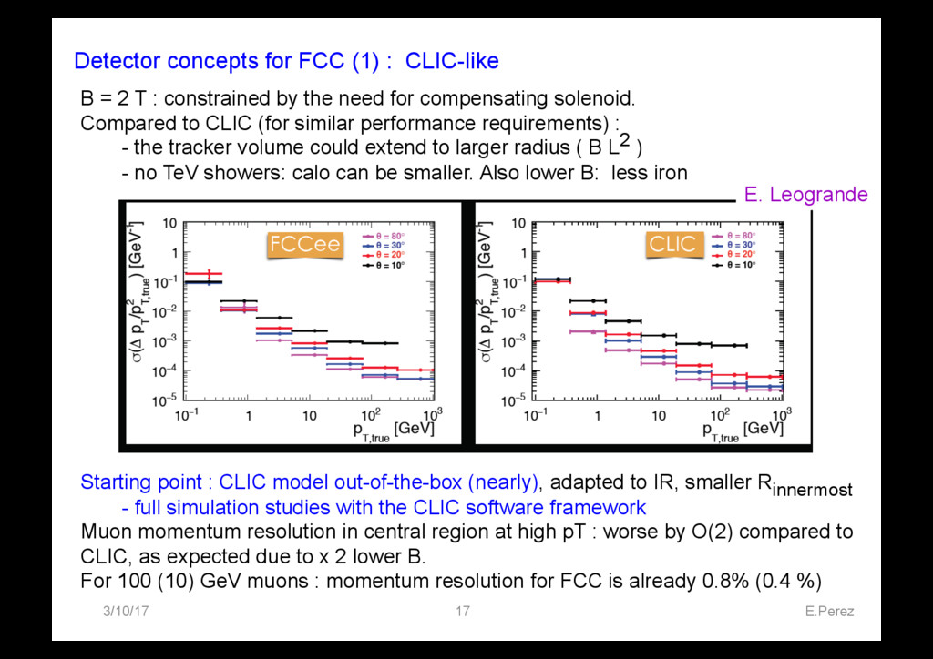
B = 2 T : constrained by the need for compensating solenoid. Compared to CLIC (for similar performance requirements) : - the tracker volume could extend to larger radius ( B L2 ) - no TeV showers: calo can be smaller. Also lower B: less iron Starting point : CLIC model out-of-the-box (nearly), adapted to IR, smaller Rinnermost - full simulation studies with the CLIC software framework Muon momentum resolution in central region at high pT : worse by O(2) compared to CLIC, as expected due to x 2 lower B. For 100 (10) GeV muons : momentum resolution for FCC is already 0.8% (0.4 %) E. Leogrande
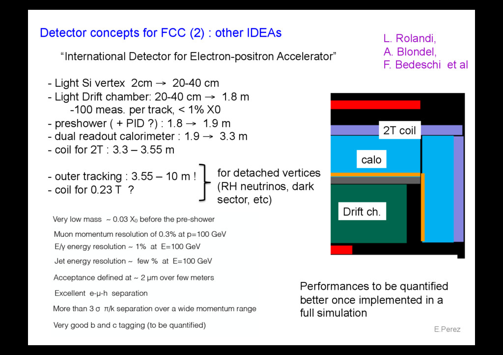
18 - Light Si vertex 2cm → 20-40 cm - Light Drift chamber: 20-40 cm → 1.8 m - 100 meas. per track, < 1% X0 - preshower ( + PID ?) : 1.8 → 1.9 m - dual readout calorimeter : 1.9 → 3.3 m - coil for 2T : 3.3 – 3.55 m - outer tracking : 3.55 – 10 m ! - coil for 0.23 T ? “International Detector for Electron-positron Accelerator” L. Rolandi, A. Blondel, F. Bedeschi et al for detached vertices (RH neutrinos, dark sector, etc) calo 2T coil Drift ch. Performances to be quantified better once implemented in a full simulation
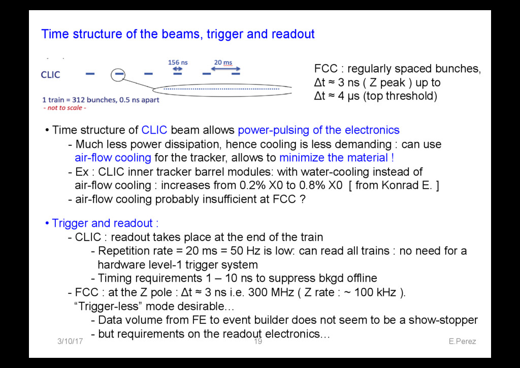
19 FCC : regularly spaced bunches, Δt ≈ 3 ns ( Z peak ) up to Δt ≈ 4 µs (top threshold) • Time structure of CLIC beam allows power-pulsing of the electronics - Much less power dissipation, hence cooling is less demanding : can use air-flow cooling for the tracker, allows to minimize the material ! - Ex : CLIC inner tracker barrel modules: with water-cooling instead of air-flow cooling : increases from 0.2% X0 to 0.8% X0 [ from Konrad E. ] - air-flow cooling probably insufficient at FCC ? • Trigger and readout : - CLIC : readout takes place at the end of the train - Repetition rate = 20 ms = 50 Hz is low: can read all trains : no need for a hardware level-1 trigger system - Timing requirements 1 – 10 ns to suppress bkgd offline - FCC : at the Z pole : Δt ≈ 3 ns i.e. 300 MHz ( Z rate : ~ 100 kHz ). “Trigger-less” mode desirable… - Data volume from FE to event builder does not seem to be a show-stopper - but requirements on the readout electronics…
at CLIC and FCC - FCC interaction region sets constraints on - B of the experiment - the position of the Luminosity monitor - FCC : large Synchrotron Radiation - effect on detector at the top energy to be quantified while CLIC : large Beamstrahlung Still several synergies between the two communities, especially around the detector and the software.
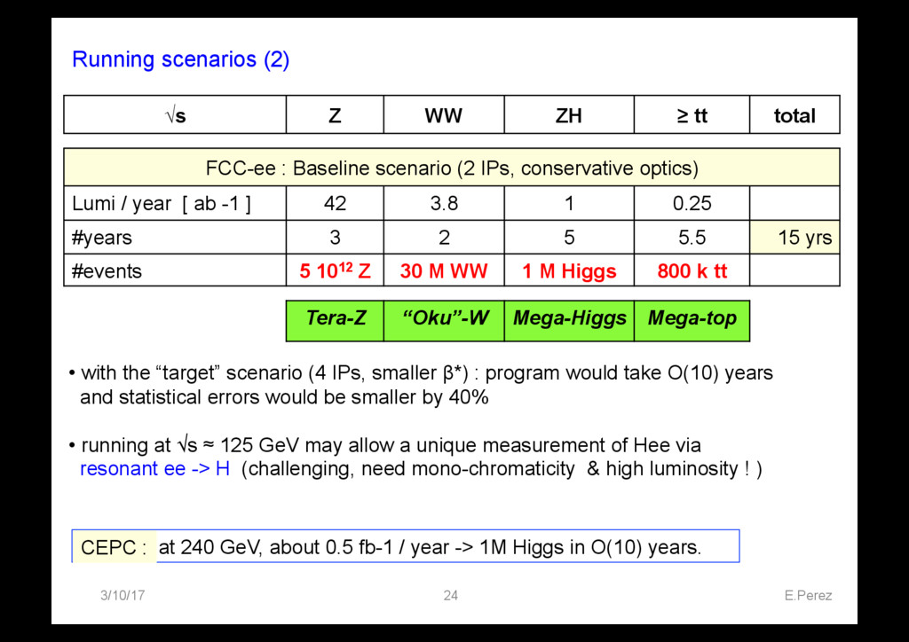
0.5 fb-1 / year -> 1M Higgs in O(10) years. CEPC : • with the “target” scenario (4 IPs, smaller β*) : program would take O(10) years and statistical errors would be smaller by 40% • running at √s ≈ 125 GeV may allow a unique measurement of Hee via resonant ee -> H (challenging, need mono-chromaticity & high luminosity ! ) √s Z WW ZH ≥ tt total FCC-ee : Baseline scenario (2 IPs, conservative optics) Lumi / year [ ab -1 ] 42 3.8 1 0.25 #years 3 2 5 5.5 15 yrs #events 5 1012 Z 30 M WW 1 M Higgs 800 k tt Tera-Z “Oku”-W Mega-Higgs Mega-top
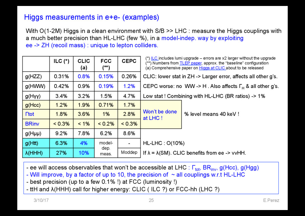
CLIC (a) FCC (**) CEPC g(HZZ) 0.31% 0.8% 0.15% 0.26% CLIC: lower stat in ZH -> Larger error, affects all other g’s. g(HWW) 0.42% 0.9% 0.19% 1.2% CEPC worse: no WW -> H . Also affects ΓH & all other g’s. g(Hγγ) 3.4% 3.2% 1.5% 4.7% Low stat ! Combining with HL-LHC (BR ratios) -> 1% g(Hcc) 1.2% 1.9% 0.71% 1.7% Won’t be done at LHC ! Γtot 1.8% 3.6% 1% 2.8% % level means 40 keV ! BRinv < 0.3% < 1% < 0.2% < 0.3% g(Hµµ) 9.2% 7.8% 6.2% 8.6% g(Htt) 6.3% 4% model- dep. meas. - HL-LHC : O(10%) λ(HHH) 27% 10% Moddep If λ = λ(SM). CLIC benefits from ee -> ννHH. (*) ILC includes lumi upgrade – errors are x2 larger without the upgrade (**) Numbers from TLEP paper, approx. the “baseline” configuration (a) Comprehensive paper on Higgs at CLIC about to be released - ee will access observables that won’t be accessible at LHC : Γtot , BRinv , g(Hcc), g(Hgg) - Will improve, by a factor of up to 10, the precision of ~ all couplings w.r.t HL-LHC - best precision (up to a few 0.1% !) at FCC (luminosity !) - ttH and λ(HHH) call for higher energy: CLIC ( ILC ?) or FCC-hh (LHC ?) With O(1-2M) Higgs in a clean environment with S/B >> LHC : measure the Higgs couplings with a much better precision than HL-LHC (few %), in a model-indep. way by exploiting ee -> ZH (recoil mass) : unique to lepton colliders.
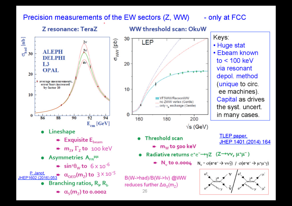
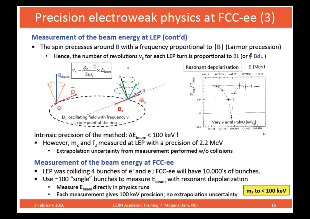
at FCC 3/10/17 E.Perez 26 Keys: • Huge stat • Ebeam known to < 100 keV via resonant depol. method (unique to circ. ee machines). Capital as drives the syst. uncert. in many cases. B(W->had)/B(W->lν) @WW reduces further ΔαS (mZ ) 100 keV 6 x 10-‐6 / 3 x 10-‐5 P. Janot, JHEP1602 (2016) 053 TLEP paper, JHEP 1401 (2014) 164
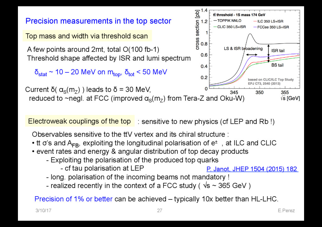
mass and width via threshold scan Current δ( αS (mZ ) ) leads to δ = 30 MeV, reduced to ~negl. at FCC (improved αS (mZ ) from Tera-Z and Oku-W) A few points around 2mt, total O(100 fb-1) Threshold shape affected by ISR and lumi spectrum Electroweak couplings of the top : sensitive to new physics (cf LEP and Rb !) Observables sensitive to the ttV vertex and its chiral structure : • tt σ’s and AFB , exploiting the longitudinal polarisation of e± , at ILC and CLIC • event rates and energy & angular distribution of top decay products - Exploiting the polarisation of the produced top quarks - cf tau polarisation at LEP - long. polarisation of the incoming beams not mandatory ! - realized recently in the context of a FCC study ( √s ~ 365 GeV ) Precision of 1% or better can be achieved – typically 10x better than HL-LHC. δstat ~ 10 – 20 MeV on mtop , δtot < 50 MeV P. Janot, JHEP 1504 (2015) 182