Share
Embed
Transcript
47 slides
-
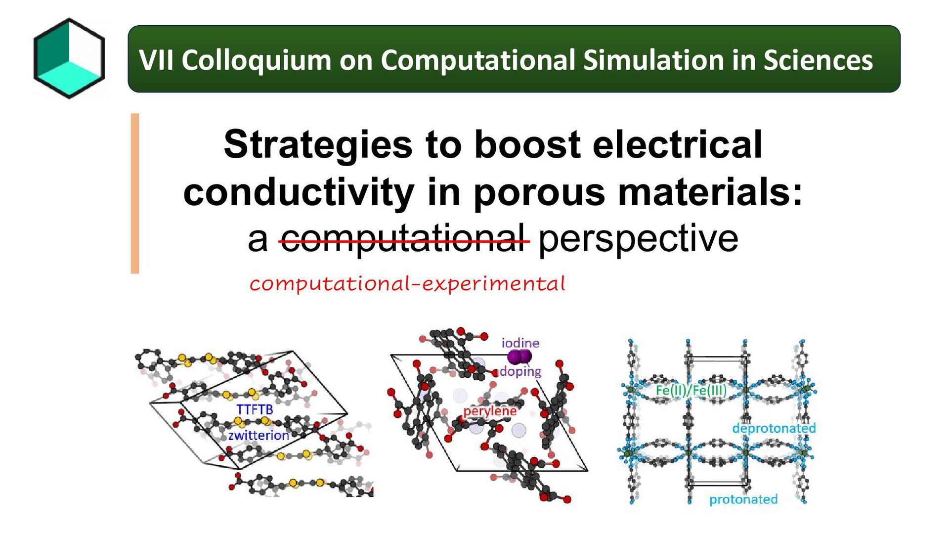
Strategies to boost electrical conductivity in porous materials: a computational
perspective computational-experimental VII Colloquium on Computational Simulation in Sciences -
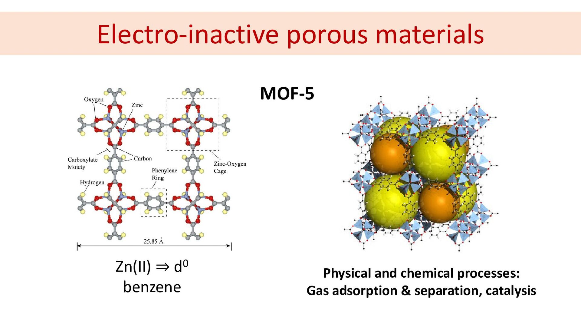
Zn(II) ⇒ d0 benzene MOF-5 Physical and chemical processes: Gas
adsorption & separation, catalysis Electro-inactive porous materials -
Computational materials design in a nutshell Methodologies Density Functional Theory
High-correlated methods Semiempirical methods Molecular Mechanics Big-data Science Properties Geometry Electronic structure REDOX and magnetism Excited states Charge and energy transport -
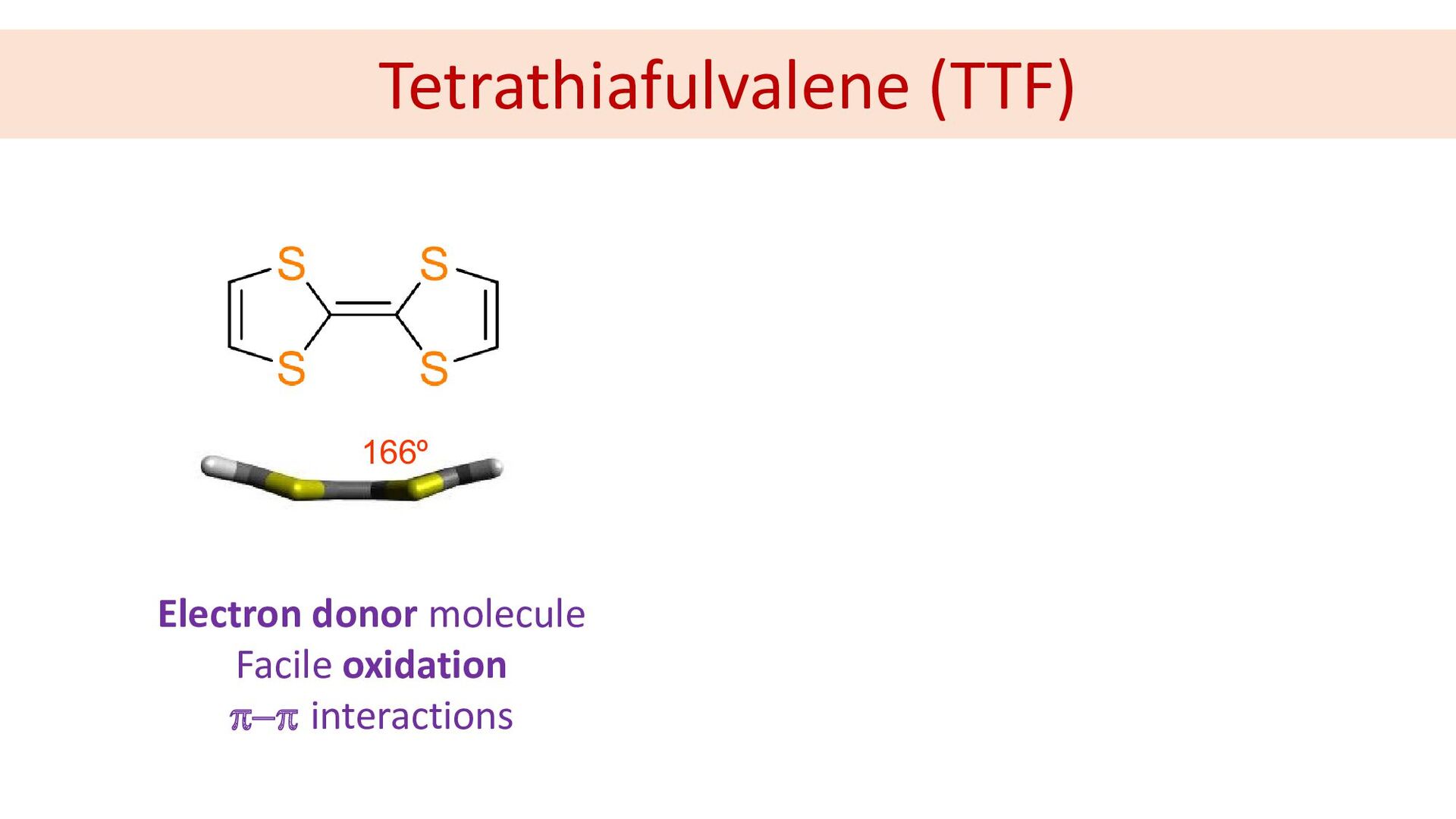
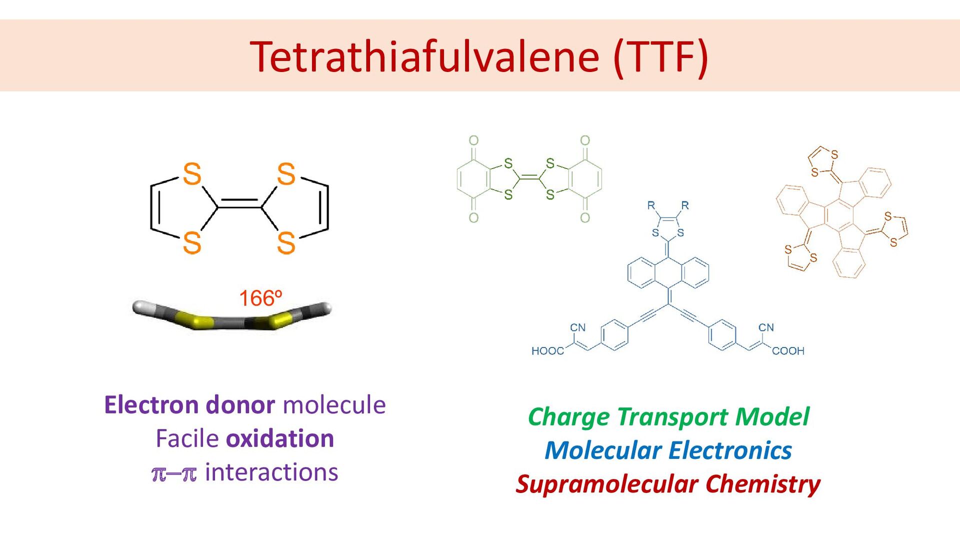
Tetrathiafulvalene (TTF) Electron donor molecule Facile oxidation π−π interactions Charge
Transport Model Molecular Electronics Supramolecular Chemistry 166º -
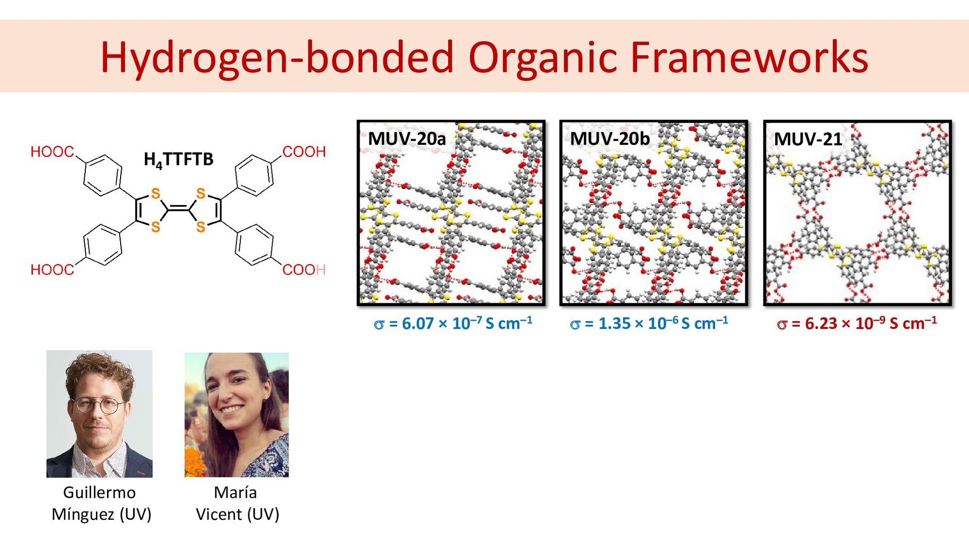
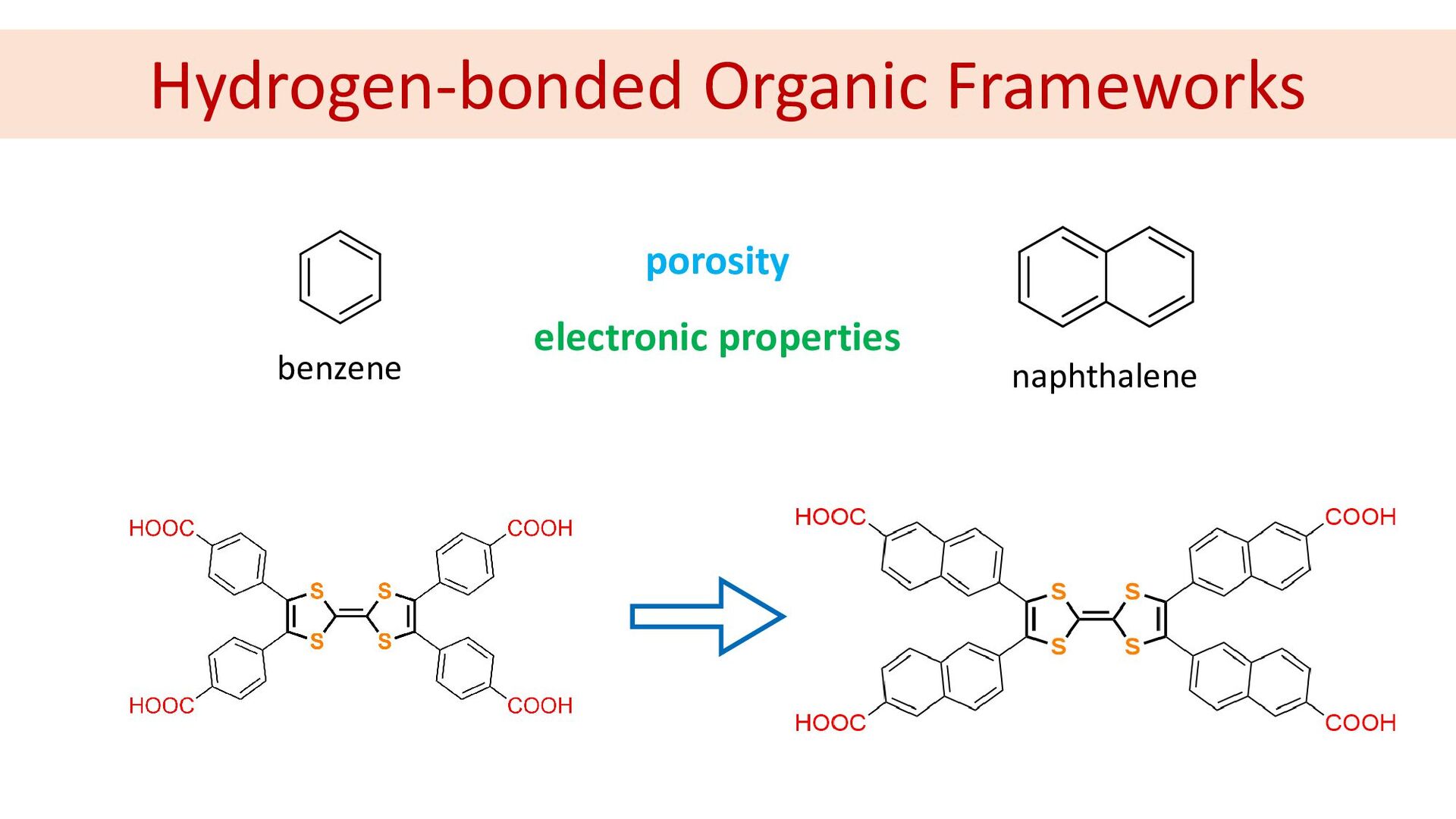
Hydrogen-bonded Organic Frameworks H4 TTFTB MUV-20a MUV-20b MUV-21 σ =
6.07 × 10⁻⁷ S cm–1 σ = 1.35 × 10⁻⁶ S cm–1 σ = 6.23 × 10⁻⁹ S cm–1 Guillermo Mínguez (UV) María Vicent (UV) -
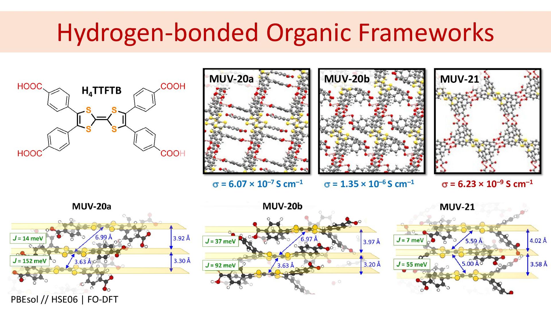
Hydrogen-bonded Organic Frameworks H4 TTFTB MUV-20a MUV-20b MUV-21 σ =
6.07 × 10⁻⁷ S cm–1 σ = 1.35 × 10⁻⁶ S cm–1 σ = 6.23 × 10⁻⁹ S cm–1 PBEsol // HSE06 | FO-DFT -
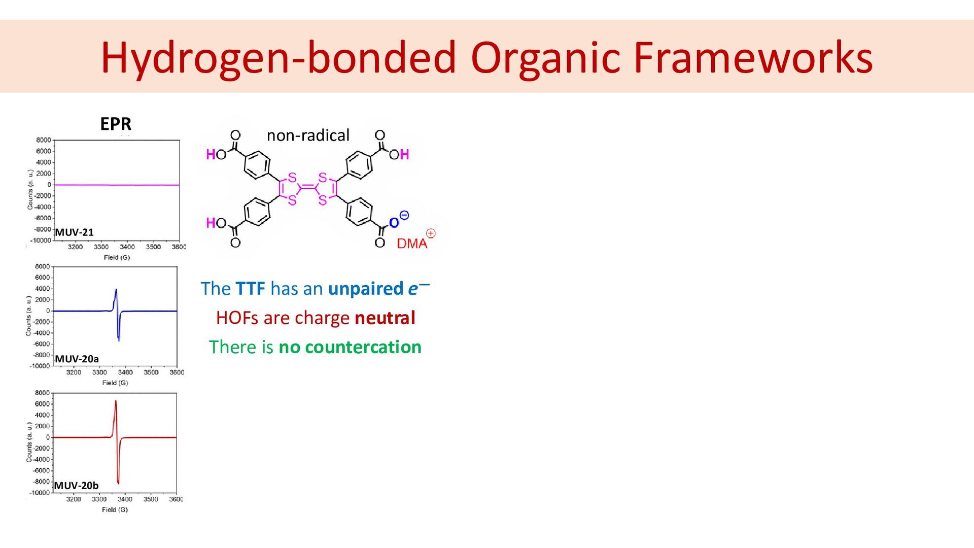
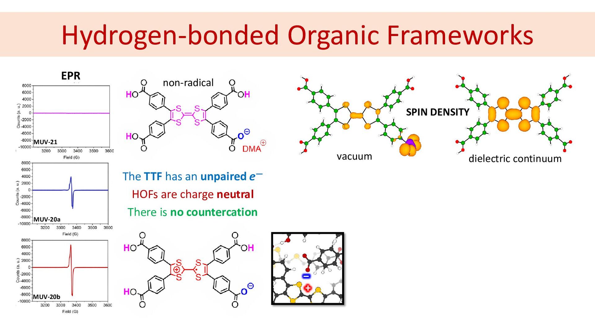
Hydrogen-bonded Organic Frameworks EPR MUV-20a MUV-21 MUV-20b The TTF has
an unpaired e― HOFs are charge neutral There is no countercation non-radical -
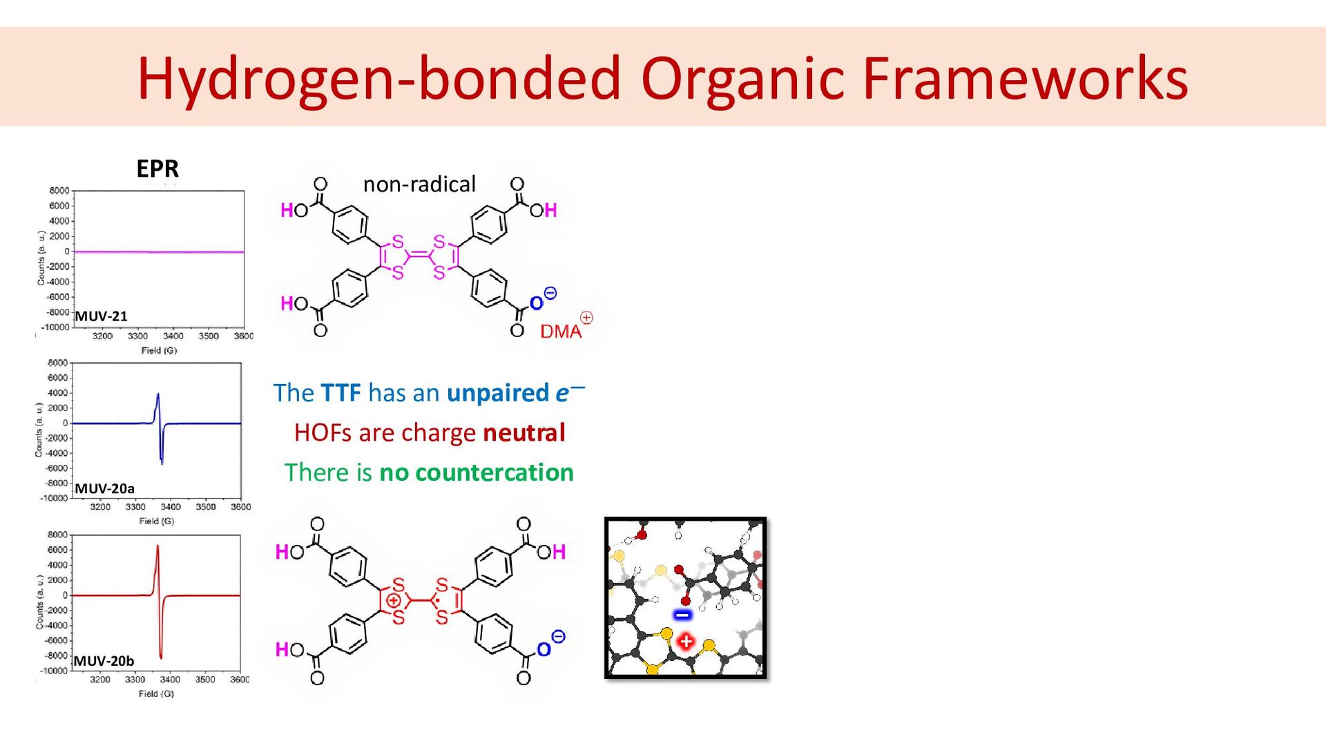
Hydrogen-bonded Organic Frameworks EPR MUV-20a MUV-21 MUV-20b The TTF has
an unpaired e― HOFs are charge neutral There is no countercation non-radical + ‒ -
Hydrogen-bonded Organic Frameworks vacuum dielectric continuum SPIN DENSITY EPR MUV-20a
MUV-21 MUV-20b The TTF has an unpaired e― HOFs are charge neutral There is no countercation non-radical + ‒ -
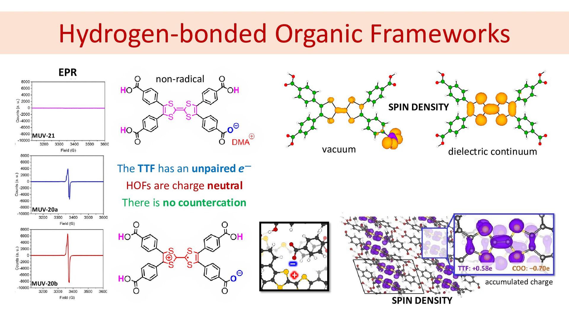
Hydrogen-bonded Organic Frameworks vacuum dielectric continuum SPIN DENSITY EPR MUV-20a
MUV-21 MUV-20b The TTF has an unpaired e― HOFs are charge neutral There is no countercation SPIN DENSITY accumulated charge non-radical + ‒ -
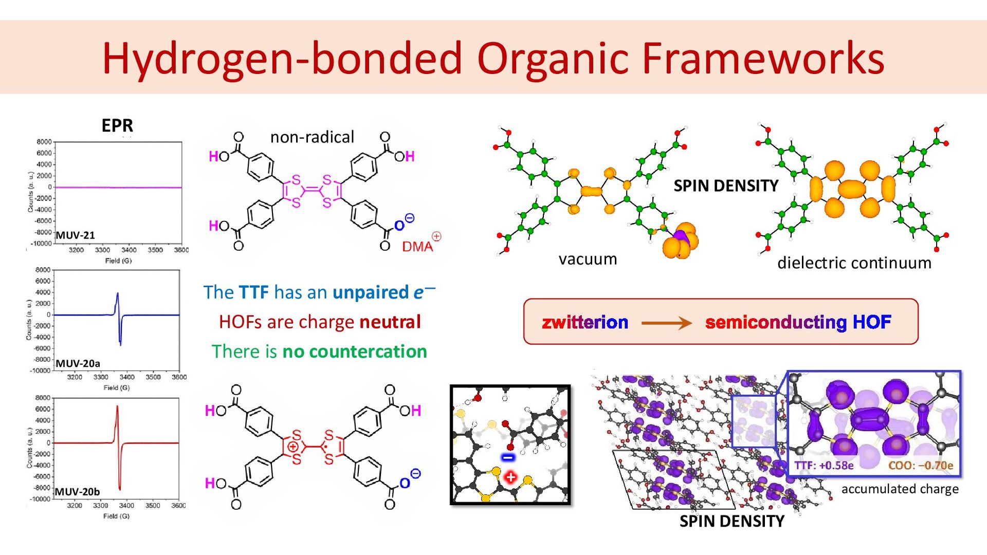
Hydrogen-bonded Organic Frameworks vacuum dielectric continuum SPIN DENSITY EPR MUV-20a
MUV-21 MUV-20b The TTF has an unpaired e― HOFs are charge neutral There is no countercation SPIN DENSITY accumulated charge non-radical + ‒ -
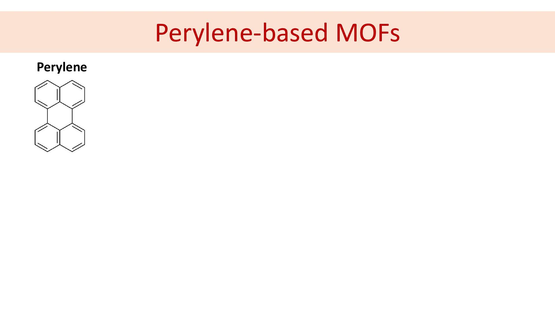
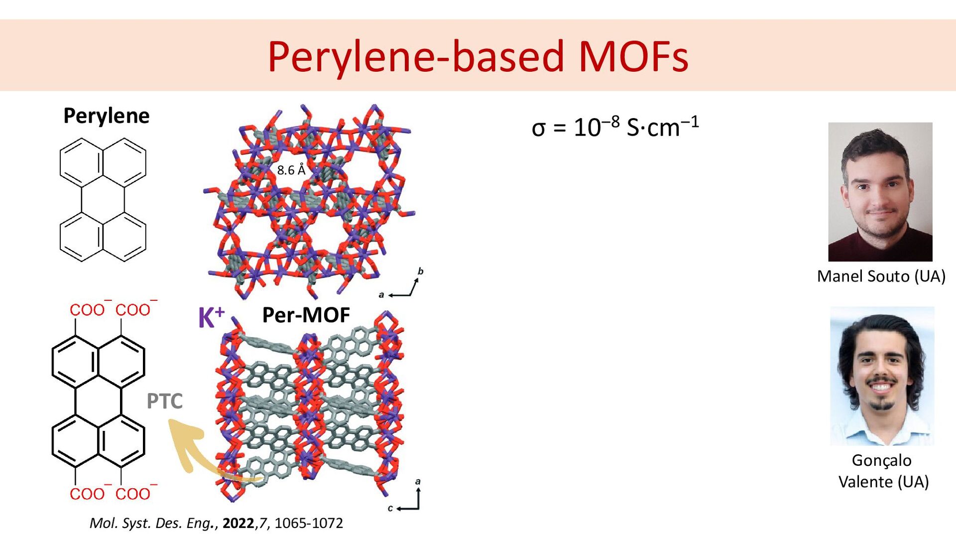
Perylene-based MOFs Manel Souto (UA) Gonçalo Valente (UA) Perylene K+
PTC 8.6 Å Per-MOF Mol. Syst. Des. Eng., 2022,7, 1065-1072 σ = 10‒8 S·cm‒1 -
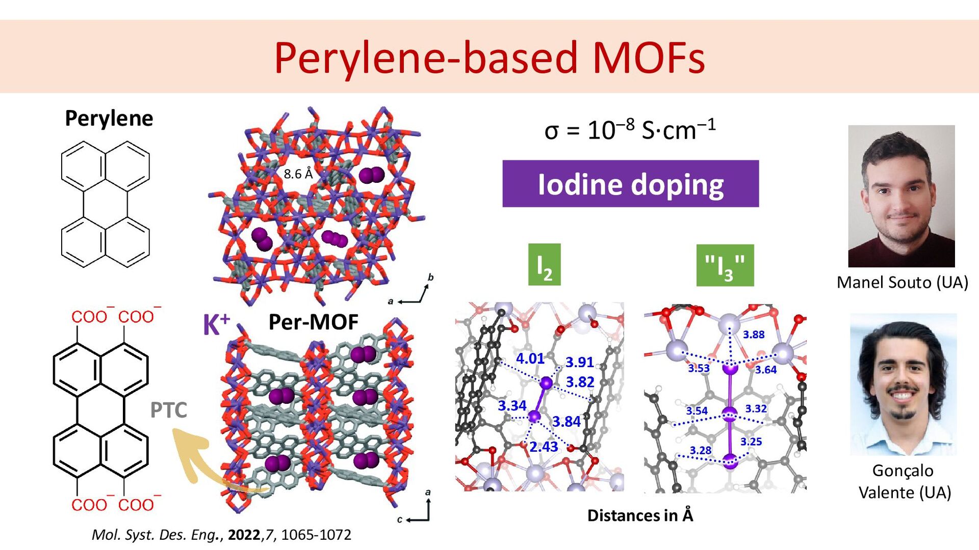
Perylene-based MOFs Manel Souto (UA) Gonçalo Valente (UA) σ =
10‒8 S·cm‒1 Iodine doping Perylene K+ PTC 8.6 Å Per-MOF Mol. Syst. Des. Eng., 2022,7, 1065-1072 Distances in Å I2 "I3 " -
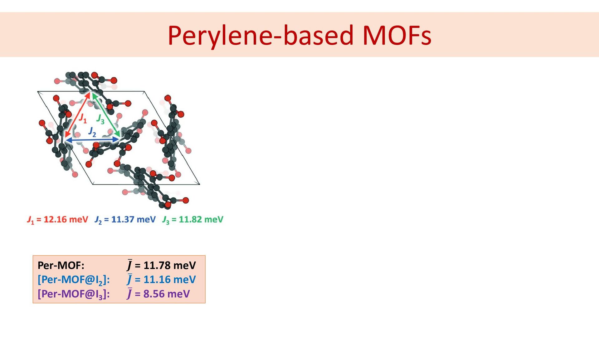
Per-MOF: ̅ 𝑱𝑱 = 11.78 meV [Per-MOF@I2 ]: ̅ 𝑱𝑱
= 11.16 meV [Per-MOF@I3 ]: ̅ 𝑱𝑱 = 8.56 meV Perylene-based MOFs -
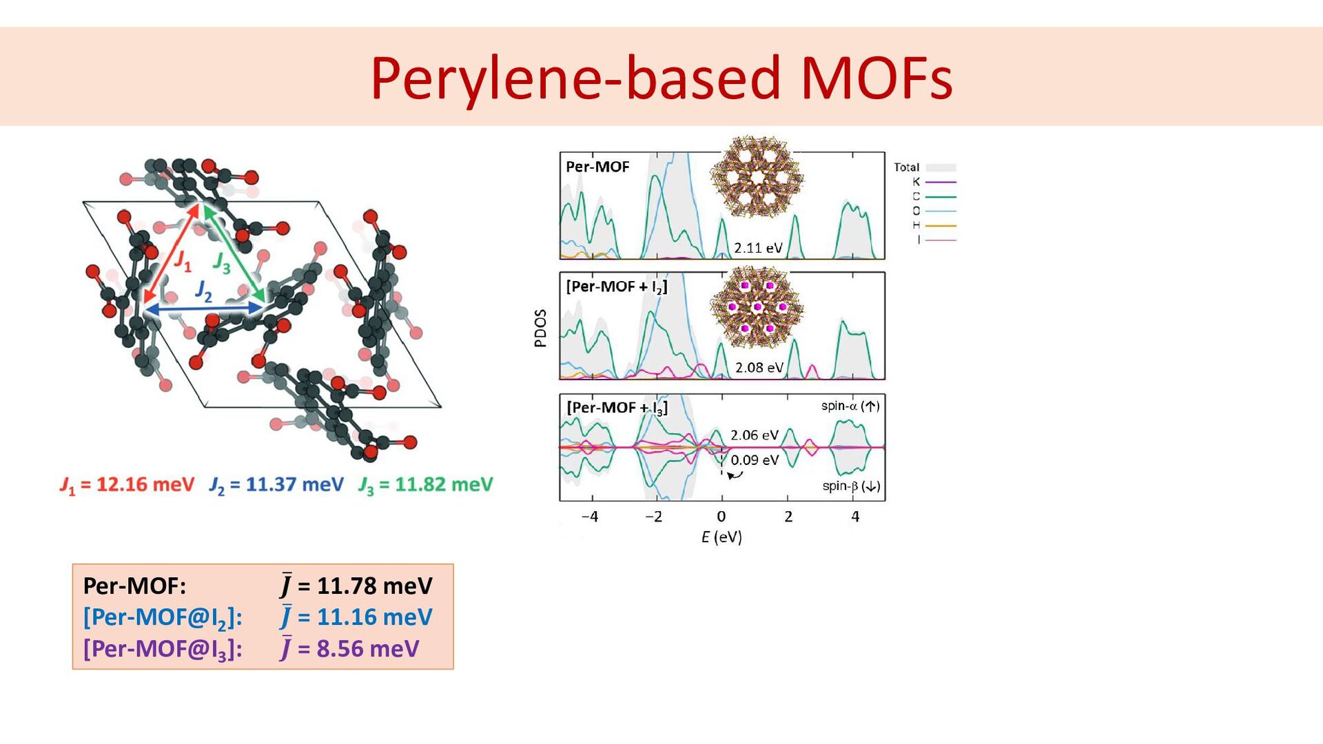
Per-MOF: ̅ 𝑱𝑱 = 11.78 meV [Per-MOF@I2 ]: ̅ 𝑱𝑱
= 11.16 meV [Per-MOF@I3 ]: ̅ 𝑱𝑱 = 8.56 meV Perylene-based MOFs -
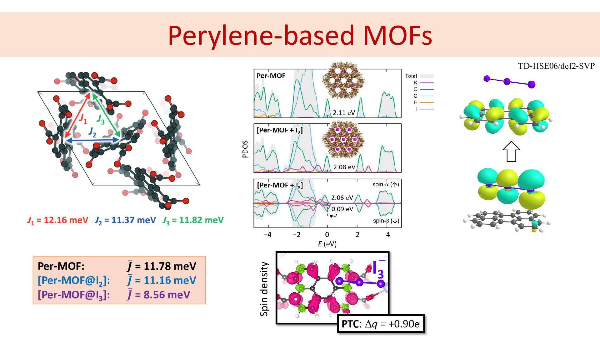
Per-MOF: ̅ 𝑱𝑱 = 11.78 meV [Per-MOF@I2 ]: ̅ 𝑱𝑱
= 11.16 meV [Per-MOF@I3 ]: ̅ 𝑱𝑱 = 8.56 meV I3 Spin density Perylene-based MOFs TD-HSE06/def2-SVP ─ -
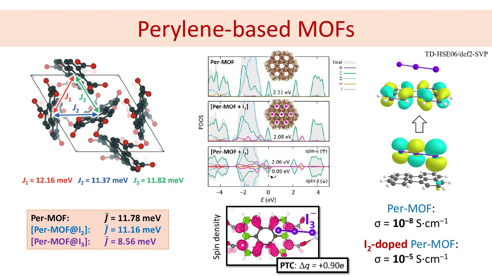
Per-MOF: ̅ 𝑱𝑱 = 11.78 meV [Per-MOF@I2 ]: ̅ 𝑱𝑱
= 11.16 meV [Per-MOF@I3 ]: ̅ 𝑱𝑱 = 8.56 meV Spin density Perylene-based MOFs Per-MOF: σ = 10‒8 S·cm‒1 I2 -doped Per-MOF: σ = 10‒5 S·cm‒1 TD-HSE06/def2-SVP I3 ─ -
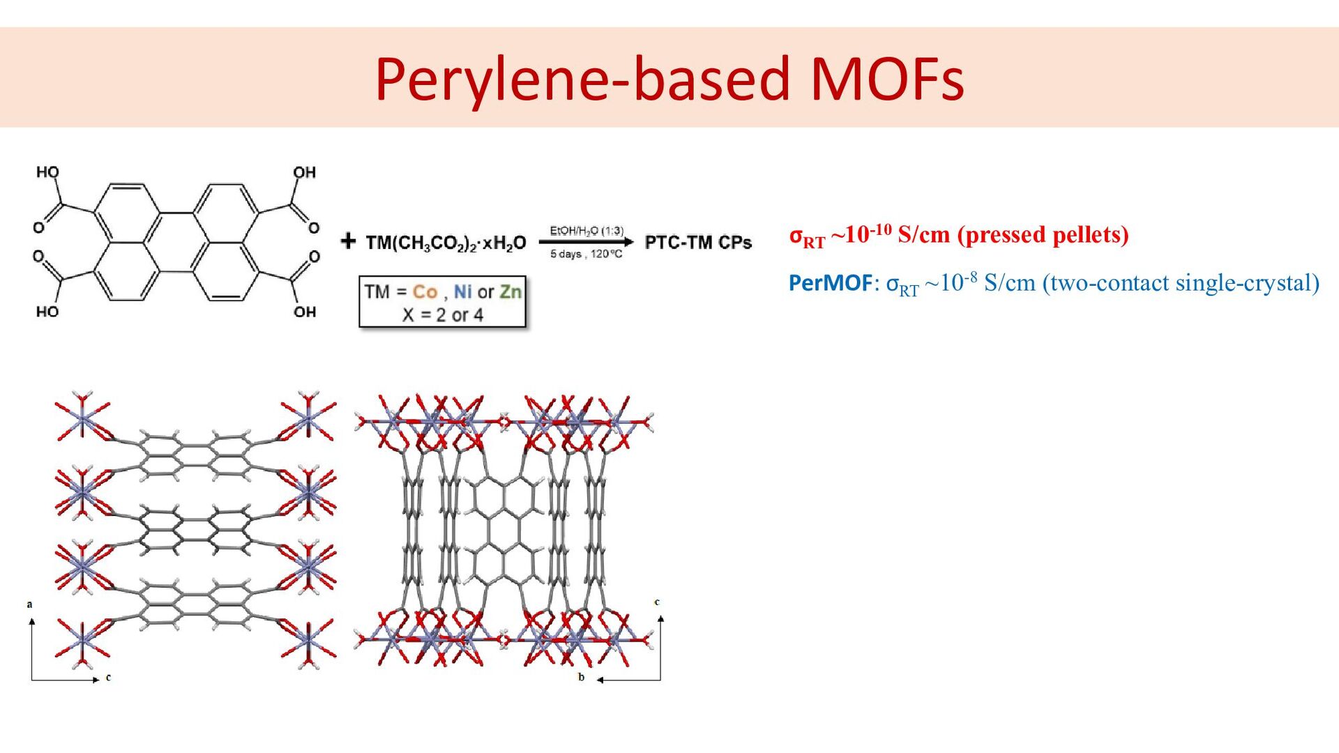
Perylene-based MOFs σRT ~10-10 S/cm (pressed pellets) PerMOF: σRT ~10-8
S/cm (two-contact single-crystal) -
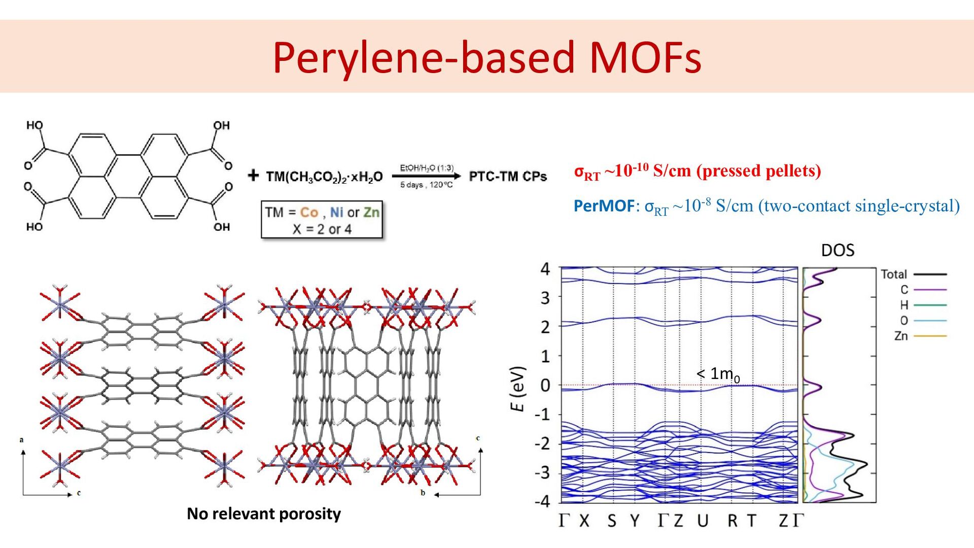
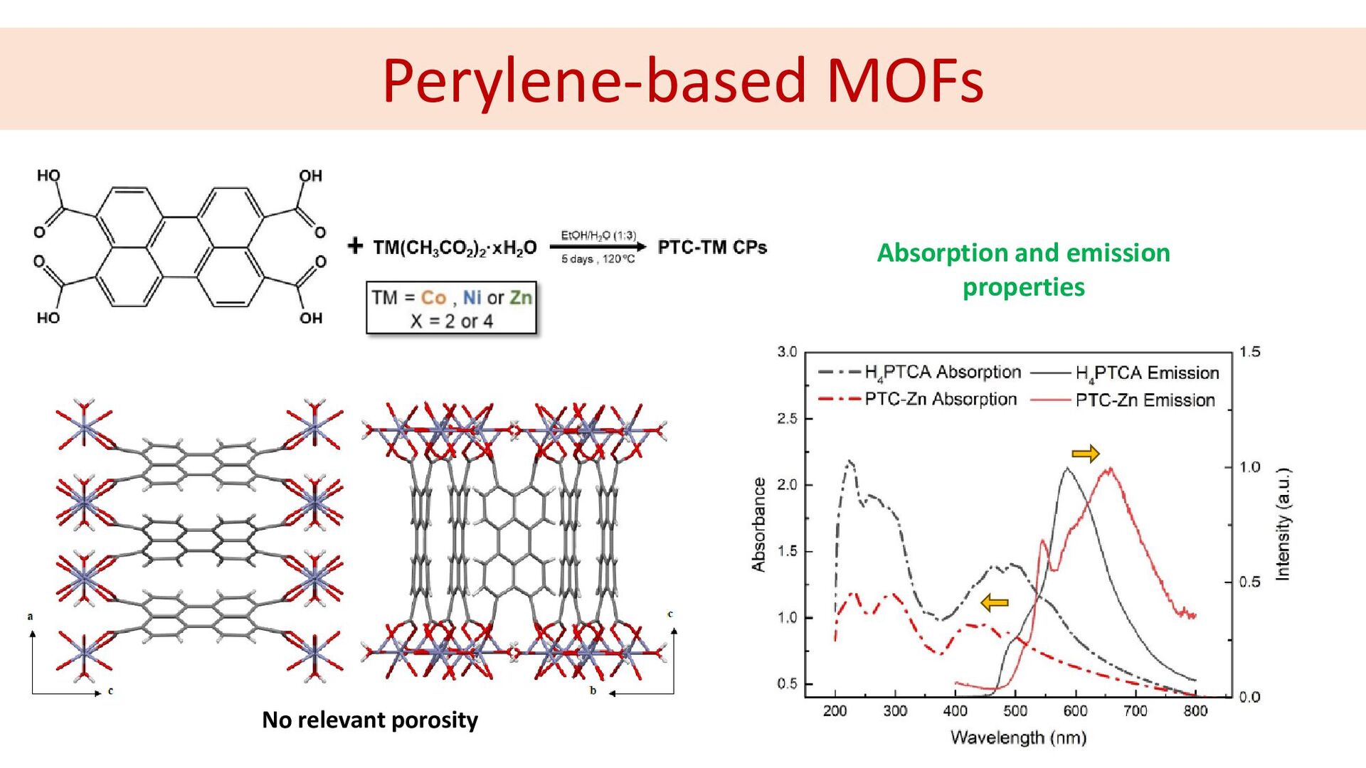
Perylene-based MOFs σRT ~10-10 S/cm (pressed pellets) PerMOF: σRT ~10-8
S/cm (two-contact single-crystal) < 1m0 No relevant porosity -
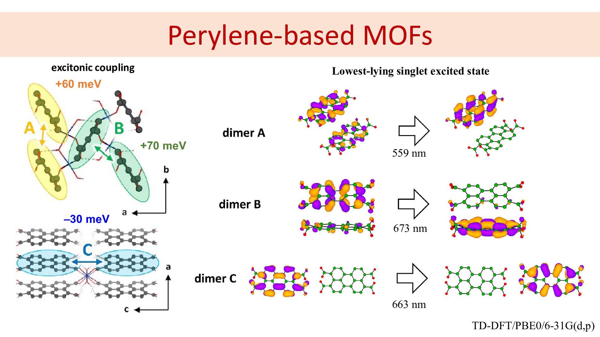
Perylene-based MOFs ‒30 meV +70 meV +60 meV 559 nm
673 nm 663 nm excitonic coupling TD-DFT/PBE0/6-31G(d,p) Lowest-lying singlet excited state -
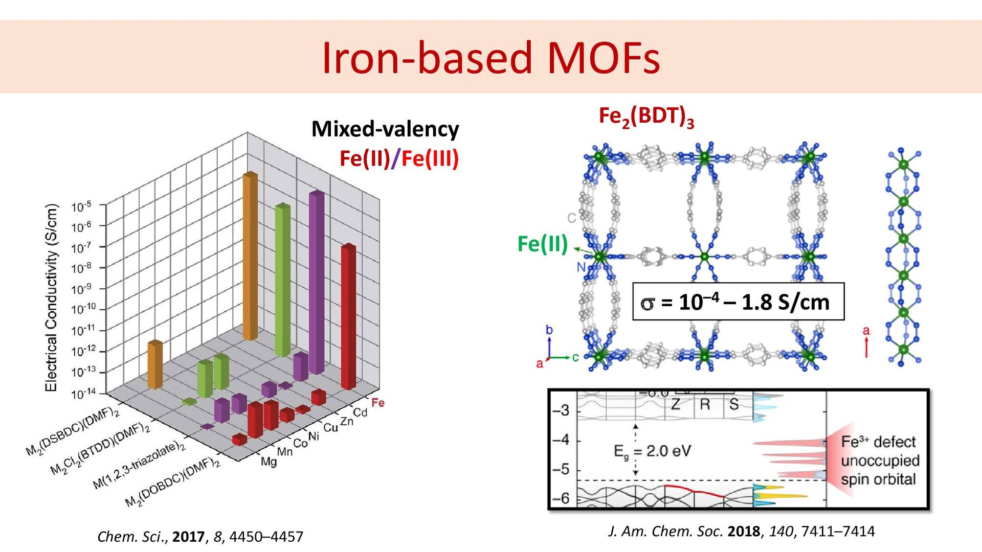
Iron-based MOFs Chem. Sci., 2017, 8, 4450–4457 Mixed-valency Fe(II)/Fe(III) Fe2
(BDT)3 J. Am. Chem. Soc. 2018, 140, 7411–7414 Fe(II) σ = 10–4 – 1.8 S/cm -
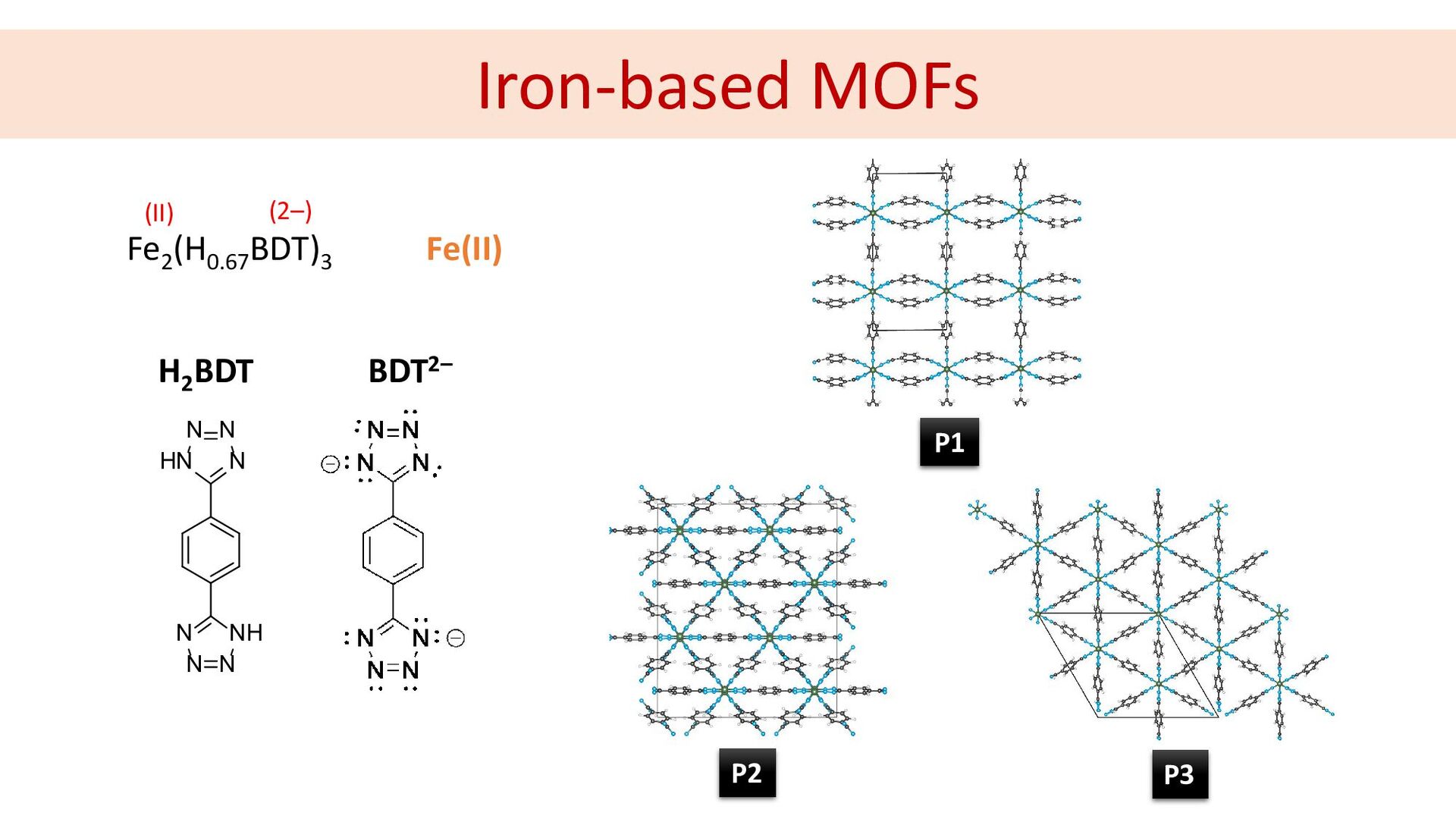
N N N NH N N N HN H2 BDT
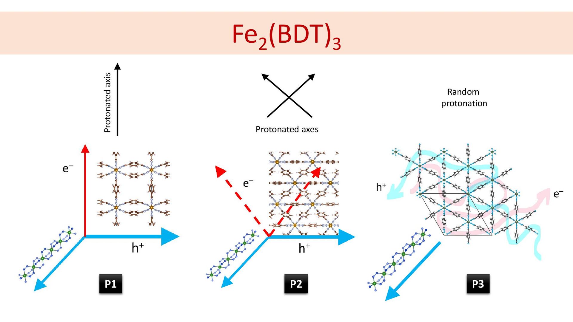
Iron-based MOFs BDT2– Fe(II) Fe2 (H0.67 BDT)3 (II) (2–) P2 P3 P1 -
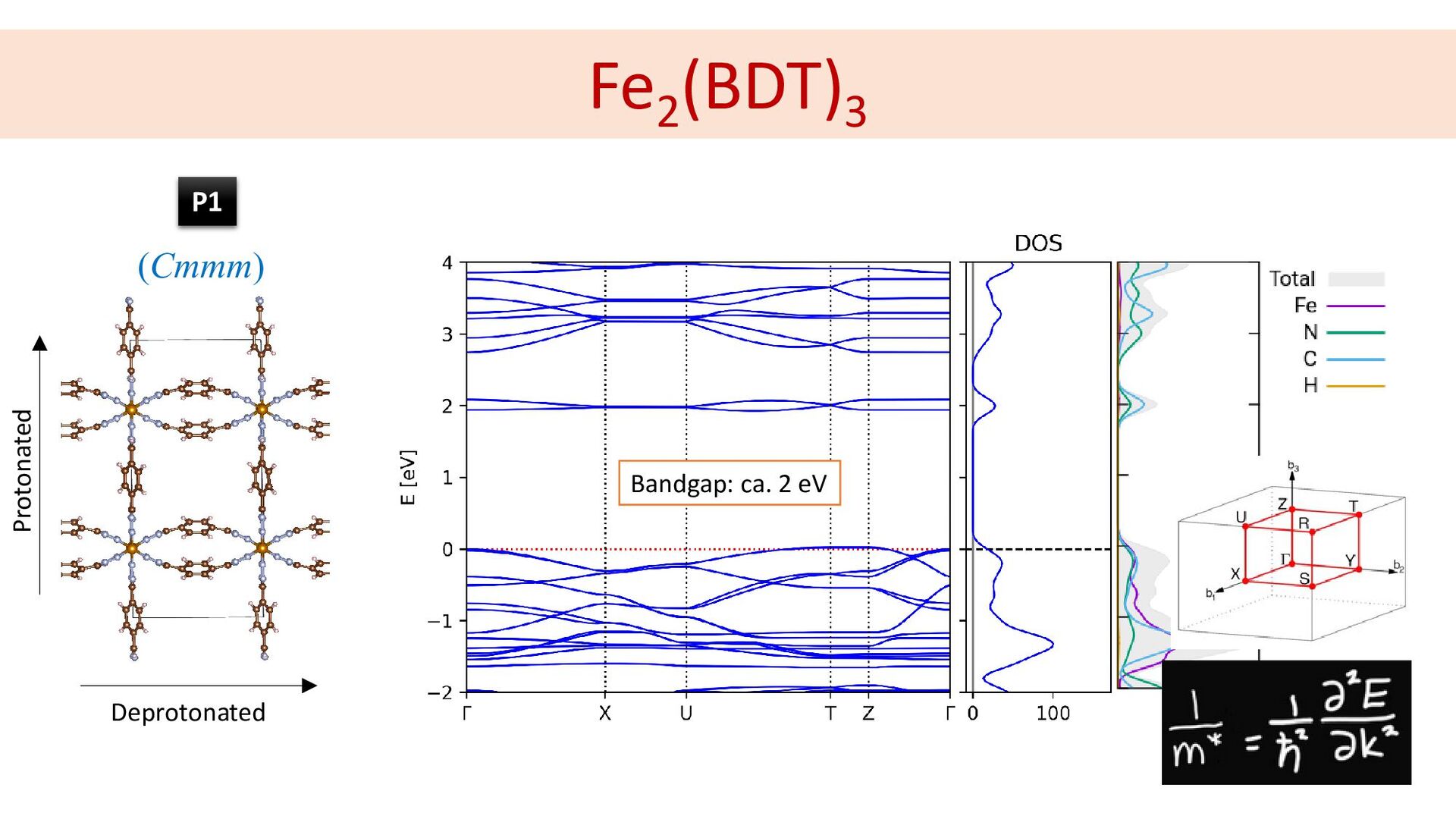
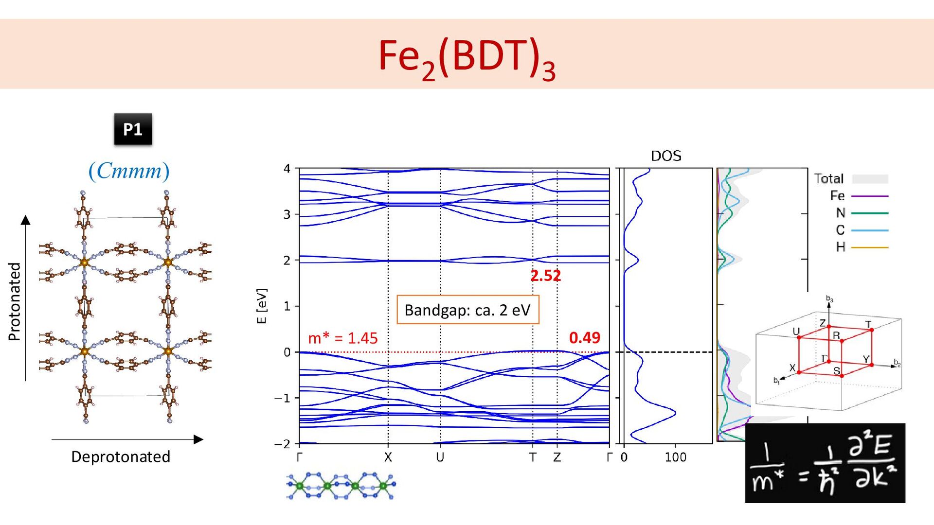
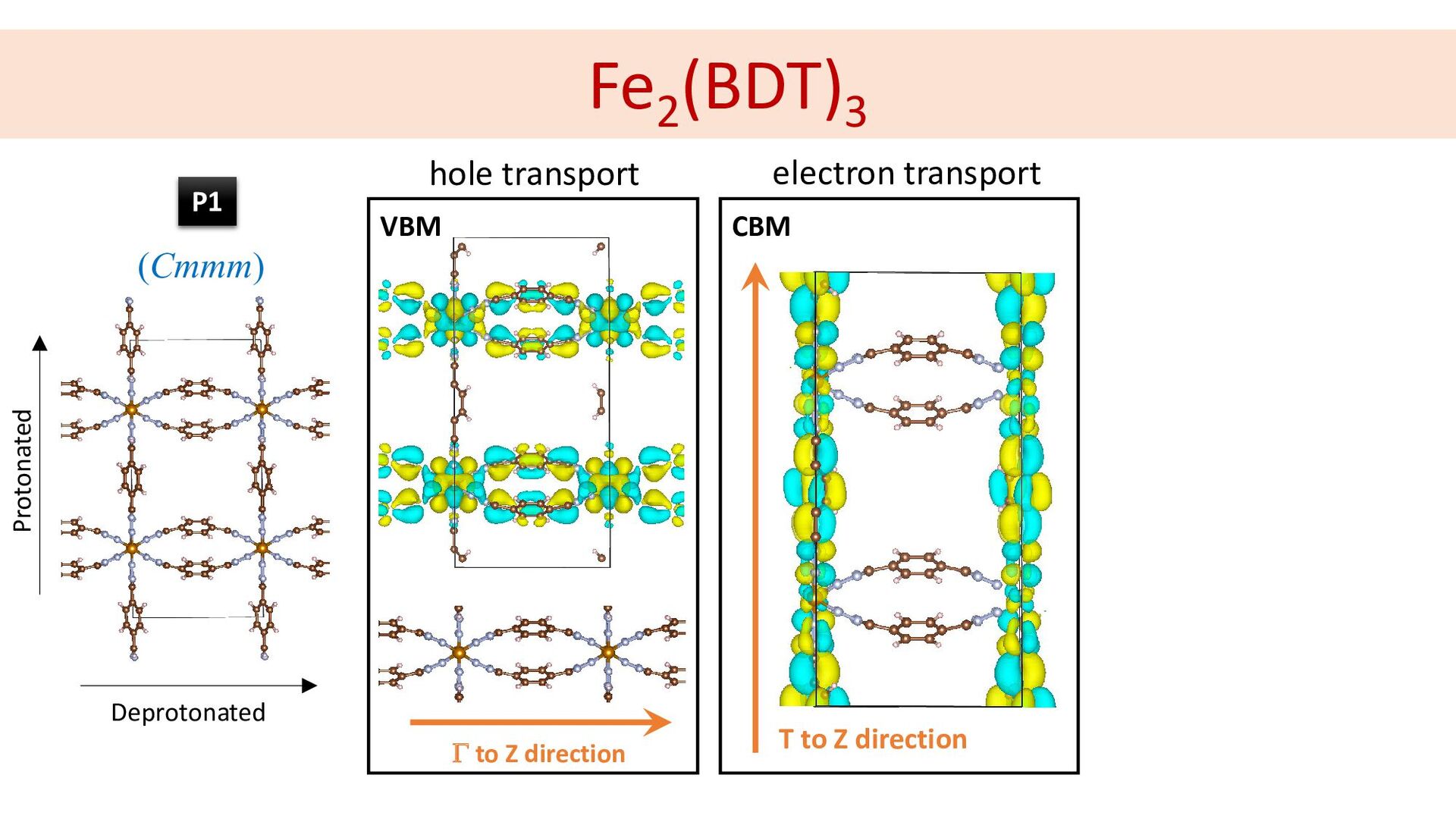
Fe2 (BDT)3 Protonated Deprotonated m* = 1.45 0.49 Bandgap: ca.
2 eV 2.52 (Cmmm) P1 -
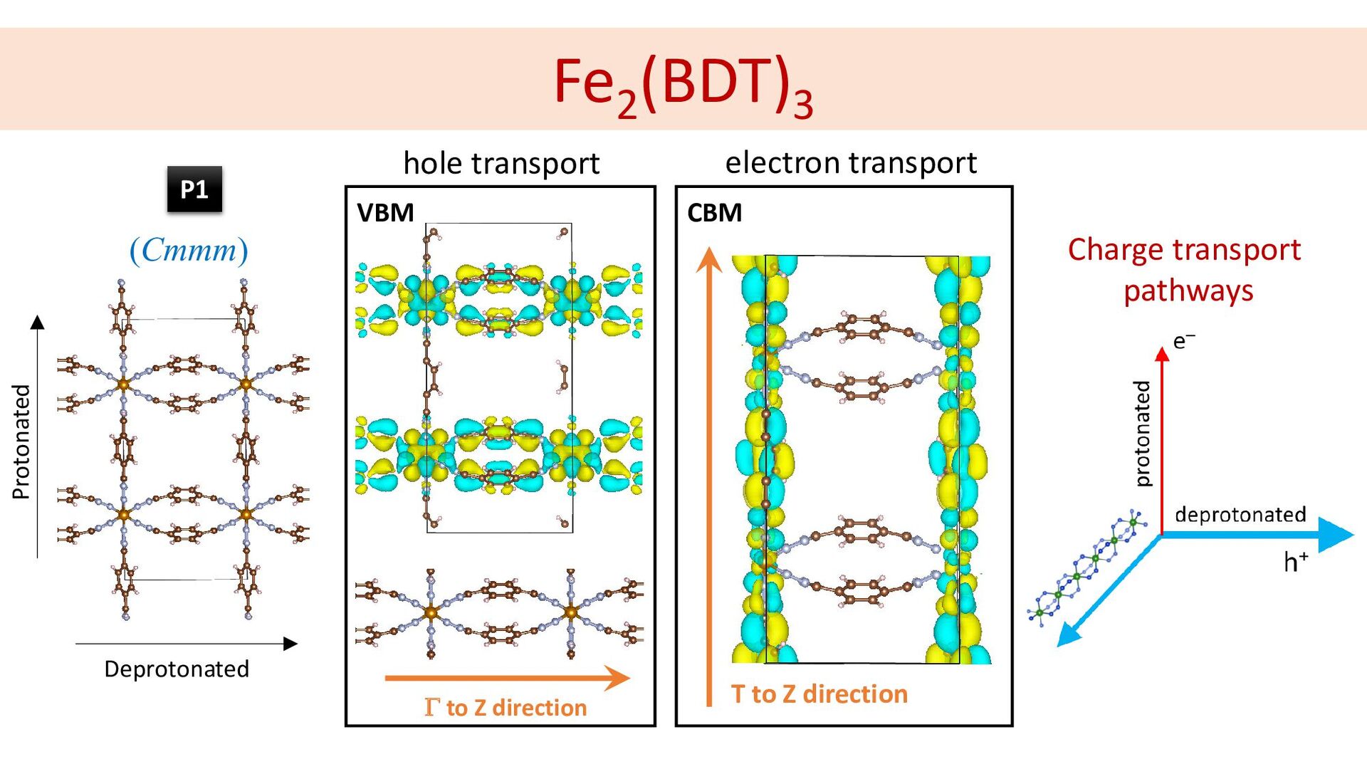
Fe2 (BDT)3 Protonated 1.45 80.31 Γ to Z direction VBM
T to Z direction CBM hole transport electron transport Deprotonated (Cmmm) P1 -
Fe2 (BDT)3 Protonated 1.45 80.31 Γ to Z direction VBM
T to Z direction CBM hole transport electron transport Deprotonated Charge transport pathways (Cmmm) P1 -
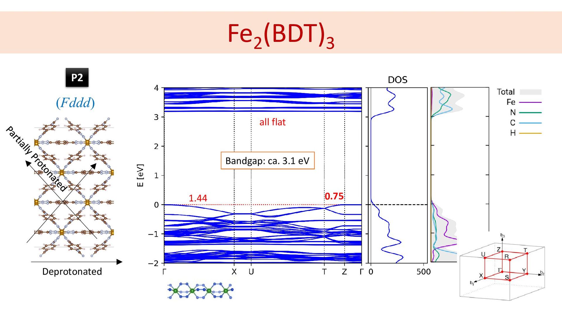
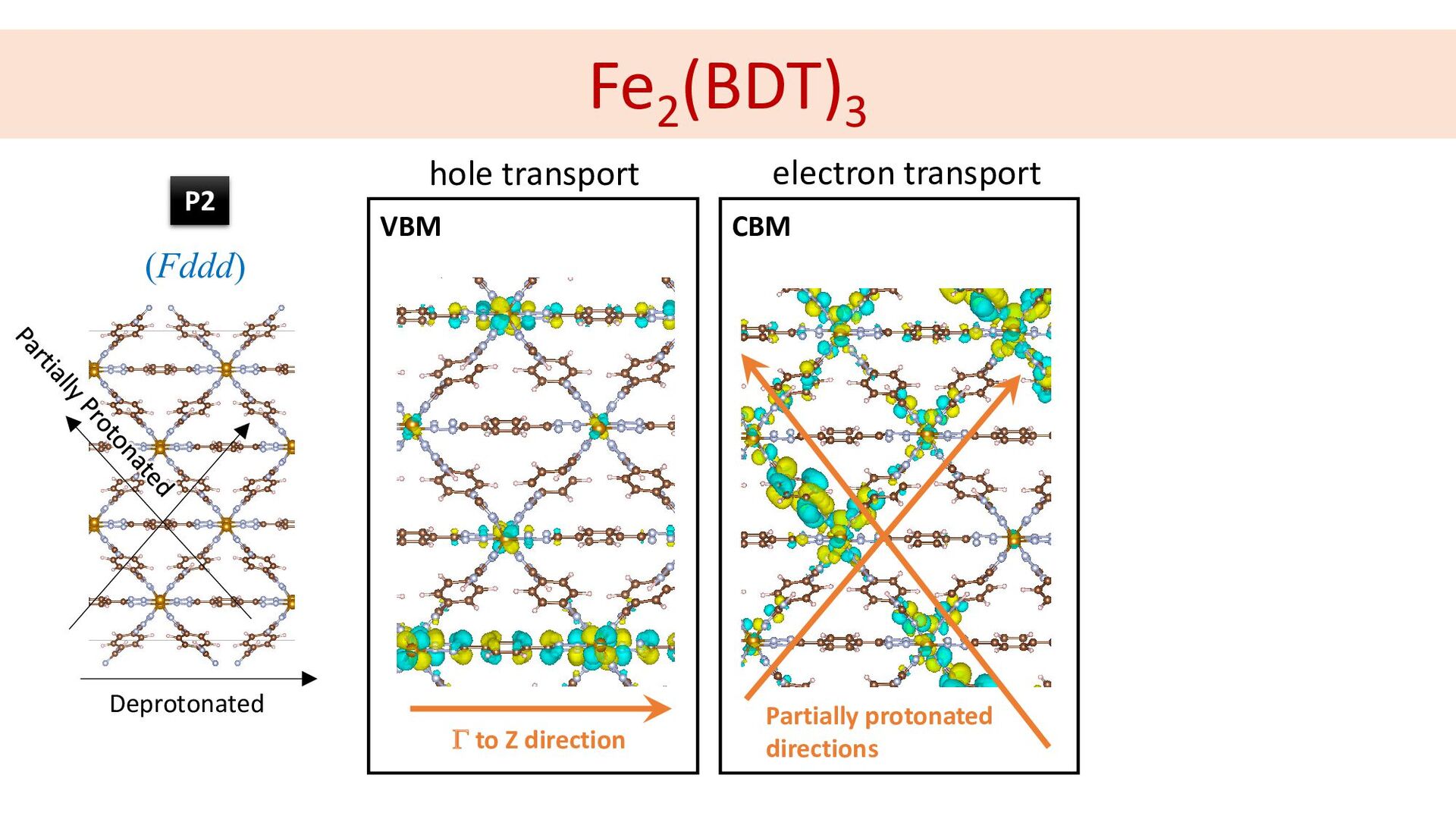
Fe2 (BDT)3 1.45 80.31 Γ to Z direction VBM CBM
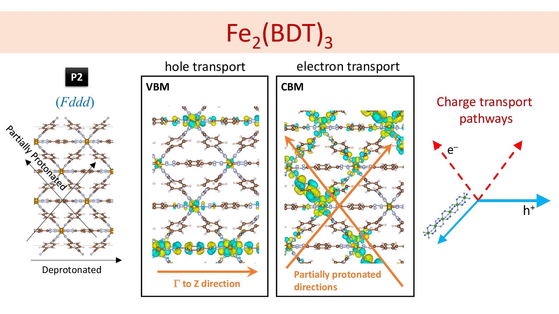
hole transport electron transport Deprotonated (Fddd) P2 Partially protonated directions -
Fe2 (BDT)3 1.45 80.31 Γ to Z direction VBM CBM
hole transport electron transport Deprotonated Partially protonated directions Charge transport pathways (Fddd) P2 -
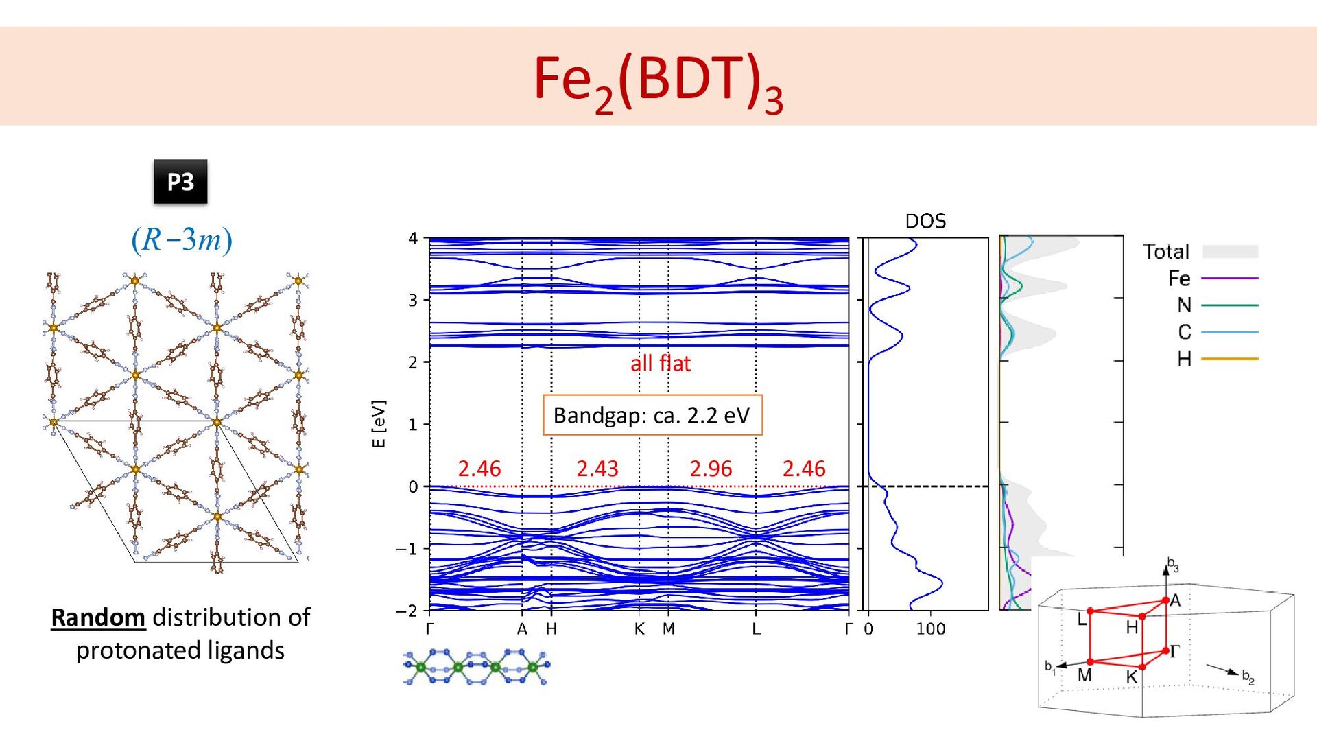
Fe2 (BDT)3 (R-3m) Random distribution of protonated ligands 2.46 2.43
2.96 2.46 all flat Bandgap: ca. 2.2 eV P3 -
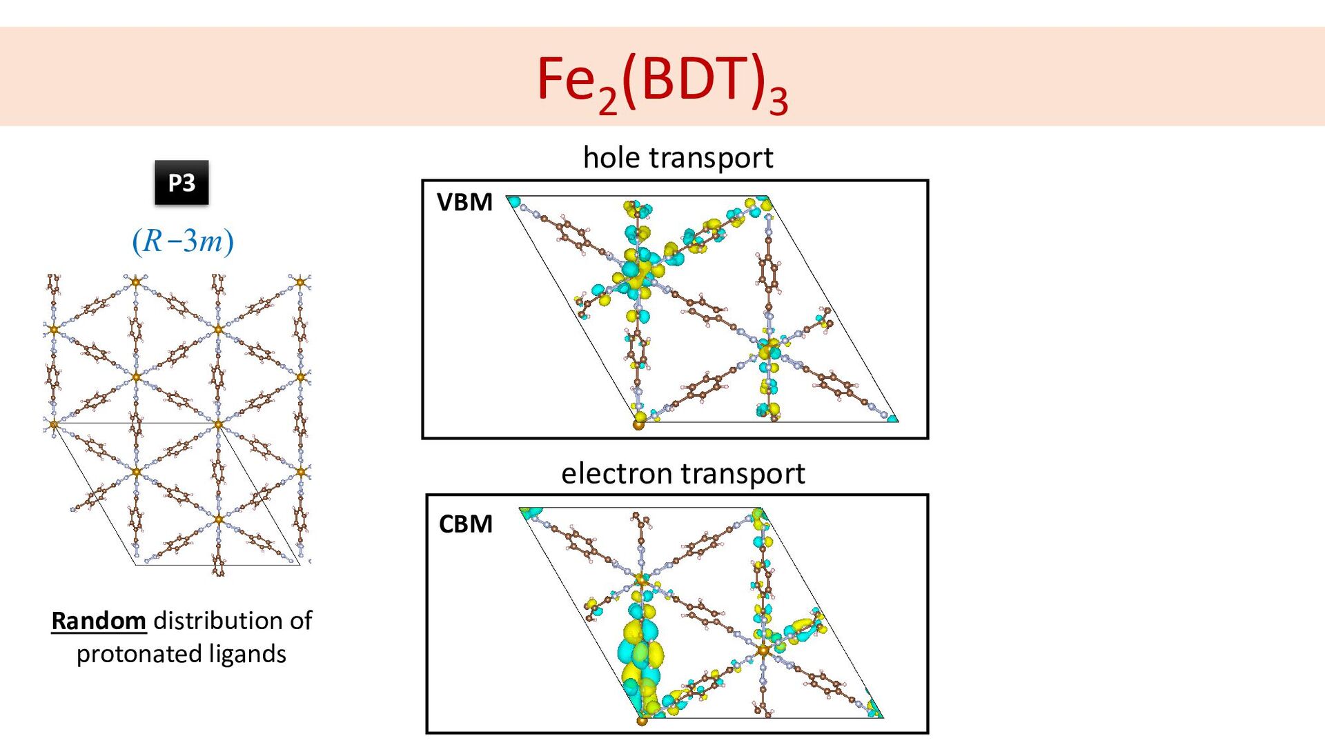
Fe2 (BDT)3 1.45 80.31 VBM CBM hole transport electron transport
Random distribution of protonated ligands (R-3m) P3 -
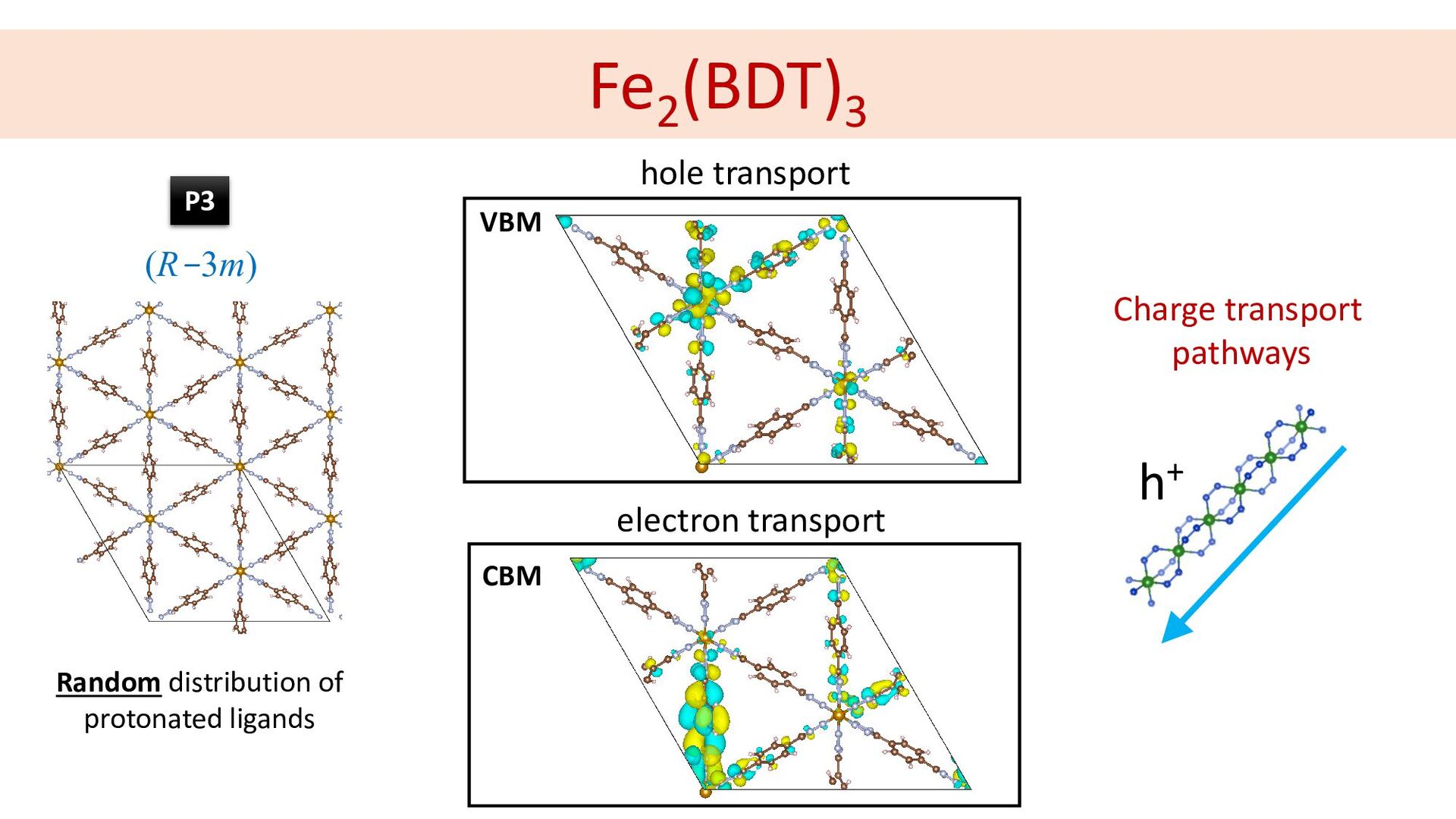
Fe2 (BDT)3 1.45 80.31 VBM CBM hole transport electron transport
Charge transport pathways Random distribution of protonated ligands h+ (R-3m) P3 -
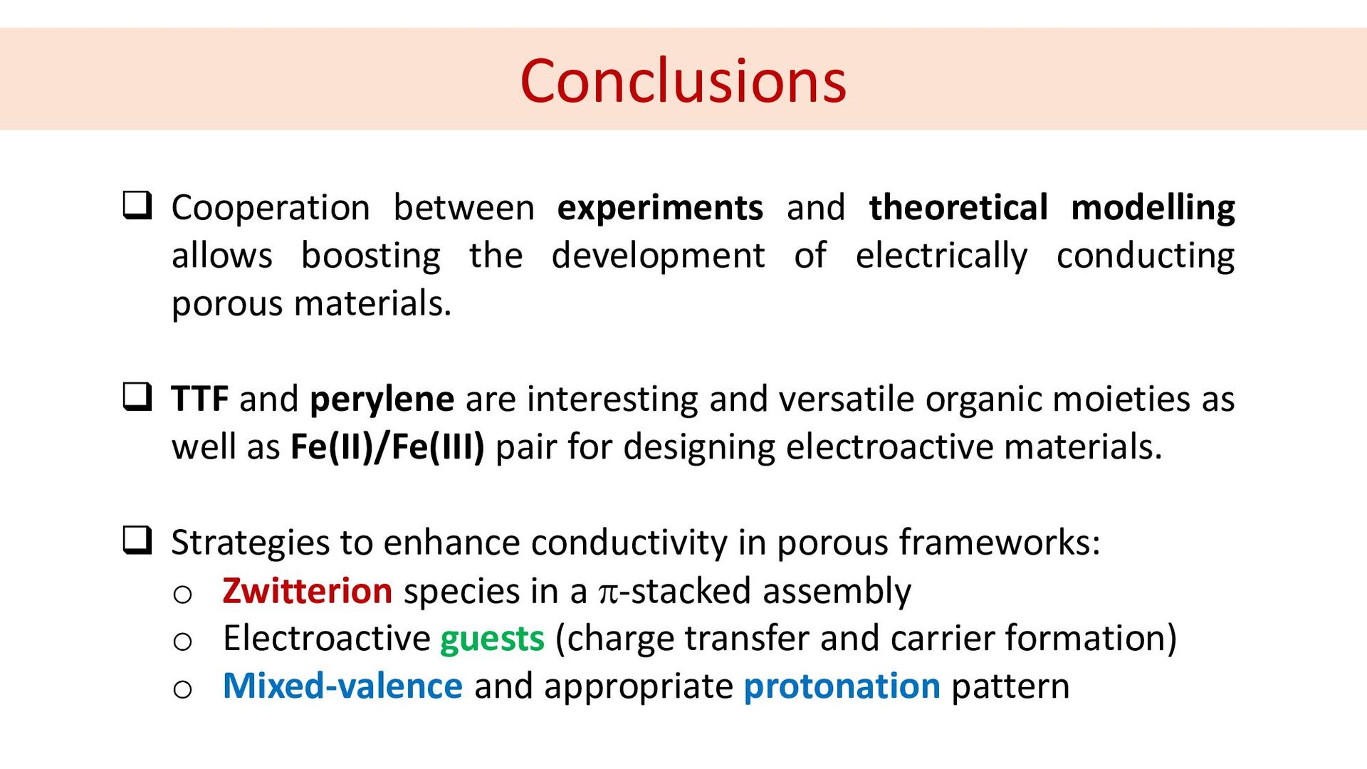
Cooperation between experiments and theoretical modelling allows boosting the
development of electrically conducting porous materials. TTF and perylene are interesting and versatile organic moieties as well as Fe(II)/Fe(III) pair for designing electroactive materials. Strategies to enhance conductivity in porous frameworks: o Zwitterion species in a π-stacked assembly o Electroactive guests (charge transfer and carrier formation) o Mixed-valence and appropriate protonation pattern Conclusions -
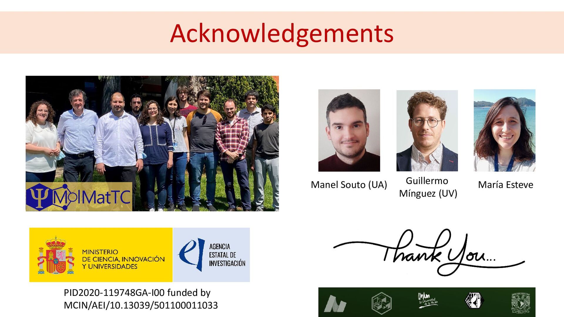
Guillermo Mínguez (UV) Acknowledgements Manel Souto (UA) María Esteve PID2020-119748GA-I00
funded by MCIN/AEI/10.13039/501100011033