Upgrade to Pro — share decks privately, control downloads, hide ads and more …

How I accidentally became an electronics engineer (actually I didn't)

How I accidentally became an electronics engineer (actually I didn't)

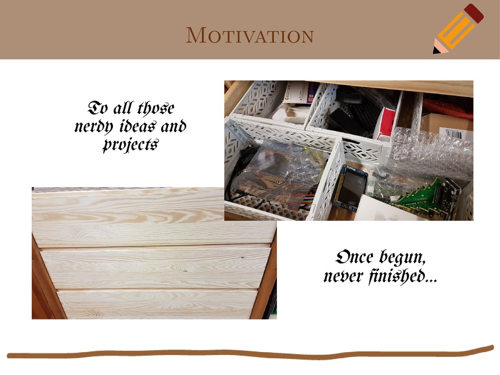
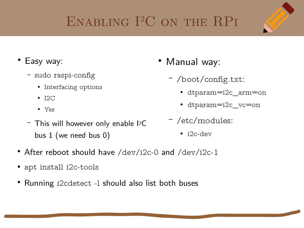
AWS, DNS, K8S. We're being exposed to IT so much at work that some of us just call it a day and refrain from any hobbyist computer stuff in our private time and maybe you have also more important responsibilities to take care of such as family. But maybe you do still from time to time try to pursuit a fun project. If so, and if you know the "bottom drawer syndrome" (enthusiastically started something, first lost time, then interest, now stored things away out of sight) or if can relate to "buy first, think of a purpose for it later", this talk is for you.

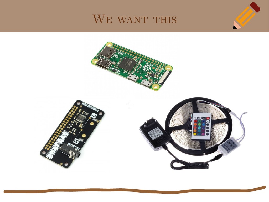
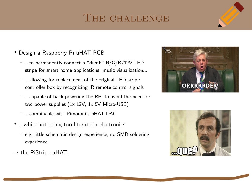
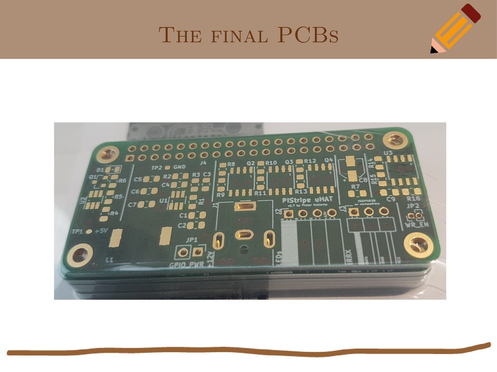
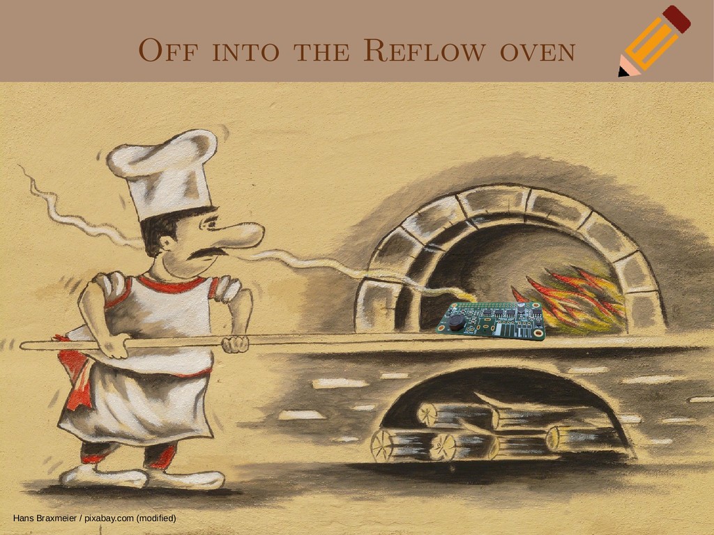
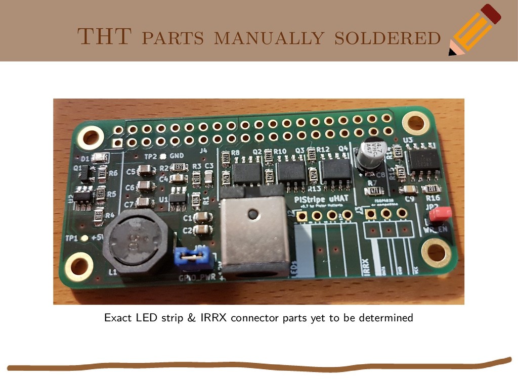
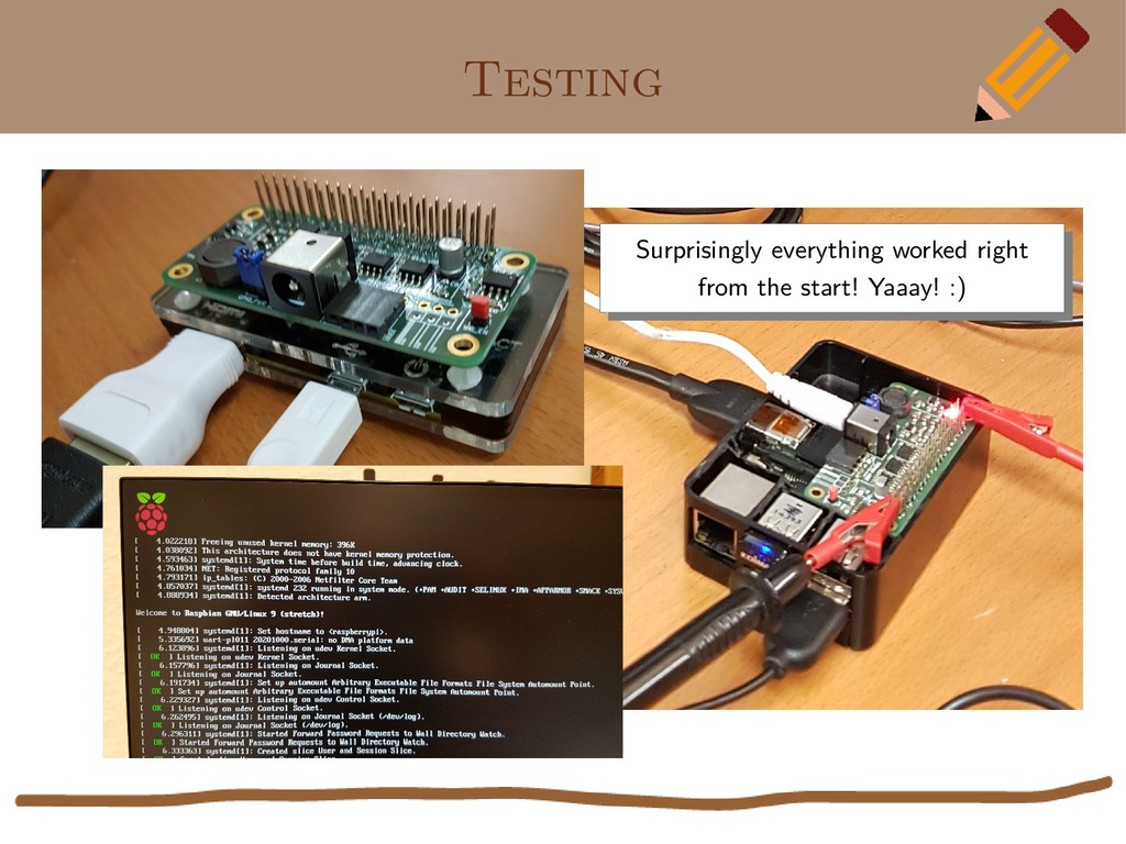
My motivation was to bring both purpose and John Bercow, I mean, orrrrder, to two such gadgets in my drawer, a Raspberry Pi and a LED stripe. In this talk I will recap and take you along on my journey during which I had to leave my usual comfort zone, that is software, and delve into hardware and electronics. Don't worry, this is not going to be a electronics 101 course. Instead I want to remedy some unwarranted fears and encourage you to look beyond the end of your (software) nose as electronics illiteracy did not stop me either from being successful as proven by my PiStripe uHAT which I'll bring along (and maybe give away one or two).

Pieter Hollants

May 04, 2019
Tweet

More Decks by Pieter Hollants

Other Decks in Technology

Transcript

  1. How I accidentally became an electronics engineer* Pieter Hollants Loadays

    2019, Antwerpen, belgium CC-BY-SA 4.0 (*: actually I didn’t)
  2. Pieter who? Frankfurt, Germany-based developer (mostly Python) but also… •

    3y IT support in Netware/Win95 times • 9y (Senior) Intern at SUSE Consulting • 4y Linux Systems Engineer at German Air Traffic Control (e.g. automated installations of high availability-systems, hardware standardization) ...but also freelancing since over 15y (dev & admin)
  3. Pieter who? Frankfurt, Germany-based developer (mostly Python) but also… •

    3y IT support in Netware/Win95 times • 9y (Senior) Intern at SUSE Consulting • 4y Linux Systems Engineer at German Air Traffic Control (e.g. automated installations of high availability-systems, hardware standardization) ...and freelancing since over 15y (dev & admin) Antonio Gullem / Adobe Stock Antonio Gullem / Adobe Stock
  4. Pieter who? Frankfurt, Germany-based developer (mostly Python) but also… •

    3y IT support in Netware/Win95 times • 9y (Senior) Intern at SUSE Consulting • 4y Linux Systems Engineer at German Air Traffic Control (e.g. automated installations of high availability-systems, hardware standardization) ...and freelancing since over 15y (dev & admin) Antonio Gullem / Adobe Stock
  5. Pieter who? Frankfurt, Germany-based developer (mostly Python) but also… •

    3y IT support in Netware/Win95 times • 9y (Senior) Intern at SUSE Consulting • 4y Linux Systems Engineer at German Air Traffic Control (e.g. automated installations of high availability-systems, hardware standardization) ...and freelancing since over 15y (dev & admin) Antonio Gullem / Adobe Stock; Wikipedia; SparkFun Electronics / Flickr; Yves Sorge / Flickr; Firecracker PR / Flickr
  6. Raspberry Pi HATS • All Raspberry Pis from B+ onwards

    have 40-pin GPIO headers (first 26 pins backward-compatible) • Add-on board stacked onto GPIO header that conform to RPi foundation’s specs at https://github.com/raspberrypi/hats = HAT (Hardware attached on top) • Since October 2018 uHAT spec for Pi Zero with smaller mechanical form factor • HAT spec doesn’t explicitly say anything about it but implicitly designed for one- HAT-at-a-time only (no stacking of HATs)
  7. The ID EEPROM requirement → pHAT DAC is no official

    HAT since it has no EEPROM EPROM: Erasable Programmable Read-Only Memory chip, requires EPROM burner EEPROM: Electrically Erasable PROM, can be programmed in-band (“flashing”) For “plug & play” user experience:
  8. Existing solutions • PiPixel HAT by Maniacal Labs https://www.tindie.com/products/ManiacalLabs/pipixel-raspberry-pi-led-strip-hat/ –

    Not suited for “dumb” LED stripes (whole stripe = single color, i.e. no WS2801, APA102, SK9822, LPD8806, SMD5050, Adafruit NeoPixel etc.) – No back-powering the RPi – No connection for IR receiver • ANAVI Light pHAT by Anavi Technologies https://www.crowdsupply.com/anavi-technology/light-phat – No back-powering the RPi – Large screw terminals for LED strip, flexible but I connecting my LED strip with its native connector – Additional stuff I don’t need, e.g. sensor headers
  9. The challenge • Design a Raspberry Pi uHAT PCB –

    ...to permanently connect a “dumb” R/G/B/12V LED stripe for smart home applications, music visualization... – ...allowing for replacement of the original LED stripe controller box by recognizing IR remote control signals – ...capable of back-powering the RPi to avoid the need for two power supplies (1x 12V, 1x 5V Micro-USB) – ...combinable with Pimoroni’s pHAT DAC • ...while not being too literate in electronics – e.g. little schematic design experience, no SMD soldering experience → the PiStripe uHAT! ORRRRRDER!
  10. On the Shoulders of giants • Combine existing work as

    building blocks to create something new – Alain Pannetrat: TPS54202-based schematic from “Adding a DC power jack to the Raspberry Pi” https://www.omzlo.com/articles/adding-a-dc-power-jack-to-the-raspberry-pi-v2 – Leon Anavi: LED driving circuit from “ANAVI Light pHAT” and IR receiver circuit from “ANAVI Infrared pHAT”, both published as Open Hardware (CC-BY-SA) https://github.com/AnaviTechnology/anavi-light https://github.com/AnaviTechnology/anavi-infrared – Raspberry Pi Foundation: ID EEPROM recommendations and circuit for “perfect” reverse current blocking diode – Others: Design resources such as libraries, symbols etc. • Ask for and get help, that’s what the Net isused to be for! – xor & struppi (CCC Ingolstadt): PCB design advice – Uwe Bonnes: SMD soldering help pxhere.com
  11. Designing a PCB Usual workflow: – Select suitable parts –

    Draw the schematic (parts and their connections) – Build/test prototype on breadboard – Design PCB layout (place parts and traces) – Manufacture PCB (mask, etch, cut, drill) – Solder parts on it – Testing and debugging – Large scale manufacturing Windell Oskay / Flickr
  12. ECAD solutions • Commercial (e.g. Eagle, now sold by Autodesk)

    • Open Source – Fritzing • suitable for beginners and “makers” • can also design connections on breadboard • lacks seriously in libraries, designing own components cumbersome • last update 3y ago, just in: new maintainers – KiCad • vast selection of component libraries • old and established (1992), last release: 4/2019 • widely used (e.g. by CERN)
  13. KiCAD • KiCAD’s main window, the project manager • Actually

    merely a project browser and a program launcher for separate applications – eeschema (schematic design) – pcbnew (PCB layout) – other tools (library editors, calculators...)
  14. KiCAD eeschema Wires Wires Part symbols Part symbols Virtual parts

    Virtual parts Connections Connections Unconnected pins Unconnected pins Comments Comments Structuring boxes Structuring boxes
  15. KiCAD footprint selection Symbols and already assigned footprints Symbols and

    already assigned footprints Footprints in category Footprints in category Footprint categories Footprint categories
  16. KiCAD pcbnew Part footprints Part footprints Traces Traces Physical PCB

    footprint Physical PCB footprint Fillup zones Fillup zones Printed text Printed text Layers Layers
  17. Design advice • Schematic – Use virtual symbols e.g. for

    GND and VCC – Let VCC symbols point upwards, GND symbols downwards • PCB – Dimension traces sufficiently according to expectable currents – Respect distances to neighboring traces and parts – As much GND areas as possible (e.g. GND layer with sufficent Vias) – Provision test points and allow for optional parts of schematic/PCB – SMD: size of parts (e.g. 0812) vs. size of pads (hand-soldering vs. industrial) • Use KiCad’s Design Rule Checks (DRC)
  18. the ID EEPROM A0/A1/A2 → GND: I2C Address = 0x50

    A0/A1/A2 → GND: I2C Address = 0x50 Close jumper to allow writing to EEPROM Close jumper to allow writing to EEPROM Pull-up resistors Pull-up resistors Decoupling capacitor Decoupling capacitor Chip specs: 24Cxx 3.3V I2C types, 16-bit addressed, unpaged Recommended part: OnSemi CAT24C32, 4KByte size Chip specs: 24Cxx 3.3V I2C types, 16-bit addressed, unpaged Recommended part: OnSemi CAT24C32, 4KByte size
  19. Do-it-yourself • For small prototype series / quick results •

    Masking – direct toner transfer (electric iron) or photo-resistive laminate (UV lamp) • Etching – subtractive method: acid removes unwanted copper from prefabricated laminate – chemicals = risk of injury/disposal restrictions – hard to get right the first time • Cutting – larger boards into actual PCB size • Drilling holes (e.g. for THT parts) Robert Hunt / Flickr fritzing.org
  20. Commercial services • Most manufacturers open for private customers as

    well • Affordable for 5 PCBs or more (~ €100), the faster you need ‘em, the more expensive • Usually require uploading of exported Gerber files, some also support KiCad projects directly • Some services also offer assembly (i.e. soldering parts) • Examples (no endorsements) – Germany: AISLER (aisler.net), Ätzwerk (aetzwerk.de), Beta Layout (beta-layout.com), LeitOn (leiton.de), Würth Elektronik (wedirekt.de) – Belgium/France: Advanced Circuit Boards (acb.be) – UK: PCBTrain (pcbtrain.co.uk), Quick-teck (quick-tech.co.uk) – USA: OSHPark (oshpark.com), Advanced Circuits (4pcb.com) – China: PCBCart (pcbcart.com), PCBWay (pcbway.com)
  21. Sourcing parts • Examples (no endorsements) – Arrow (arrow.com), Farnell

    (farnell.com), Mouser (mouser.com), RS Components (rs-online.com) – Conrad Electronic (conrad.com): little choice, pricey at times
  22. Soldering variants THT (Through hole technology) SMT (Surface mount technology)

    Benedikt Seidl / Wikipedia Magnus Manske / Wikipedia (modified) Manual soldering Reflow or Wave soldering Gareth Halfacree / Flickr Amazon Space11111 / Wikipedia
  23. Reflow vs. Wave soldering • PCB with SMT parts only

    • Solder paste containing solder and flux applied to solder pads using pneumatic dispenser or stencil • Parts placement with tweezers or pick-n-place machine with vacuum nozzle • Reflow oven – Batch types for laboratories, prototyping – Conveyor belt types for industrial-grade production • PCB with THT or SMT parts on solder side • Conveyor belt pulls PCB: – Flux sprayer (cleaning/to prevent oxidization) – Preheater (accelerates soldering/prevents thermal shock) – Solder wave (pump generating upwelling of melted solder) – Cooling • Too expensive for laboratories/prototyping Martin Tarr / mtarr.co.uk (via archive.org)
  24. Testing Surprisingly everything worked right from the start! Yaaay! :)

    Surprisingly everything worked right from the start! Yaaay! :)
  25. No hardware without software Programming the ID EEPROM via I2C

    • GPIO maps • DeviceTree concepts https://github.com/raspberrypi/hats Assess outcome on the OS • GPIO setup • sysfs Example code • Toggling LEDs • Reading IR codes
  26. • Inter-Integrated Circuit bus originally developed by Phillips; cousins: SMBus,

    SPI • Master-slave bus with two wires only (SDA/Data and SCL/Clock), easy to implement, used for low-speed devices such as sensors, ADCs/DACs, small memory chips, real time clocks… • Bus interface under Linux implemented by I2C adapter driver • Commands/parameters/replies different for each device → I2C client drivers • Modern RPis have two I2C buses: – Bus 0 owned by VideoCore, reserved for camera control and ID EEPROM purposes (“do not connect anything else”); HAT header pins 27 SDA/28 SCL – Bus 1 owned by ARM CPU (normally you use only this one); HAT header pins 3 SDA/5 SCL The I2C bus Wikipedia: I2C
  27. Enabling I2C on the RPi • Easy way: – sudo

    raspi-config • Interfacing options • I2C • Yes – This will however only enable I2C bus 1 (we need bus 0) • Manual way: – /boot/config.txt: • dtparam=i2c_arm=on • dtparam=i2c_vc=on – /etc/modules: • i2c-dev • After reboot should have /dev/i2c-0 and /dev/i2c-1 • apt install i2c-tools • Running i2cdetect -l should also list both buses
  28. EEPROM Reading/Writing • Could use i2cdump to dump contents but

    not to write • https://github.com/raspberrypi/hats/ provides eepromutils directory: – Reading/Writing EEPROM contents to/from .eep file: • ./eepflash.sh -r|-w -f=<eeprom file> -d=0 -a=50 -t=24c32 – Create empty .eep file for flashing to fully erase EEPROM • dd if=/dev/zero of=erase.eep bs=1k count=4 – Create binary .eep file from input textfile with EEPROM settings • ./eepmake <input textfile> <eeprom file> [<dt_file>] [<custom file...>] – Analyze existing binary .eep file (e.g. read out of EEPROM) • ./eepdump <eeprom file> <analysis textfile> eeprom.eep eepflash.sh eeprom_settings.txt analysis.txt eepmake eepdump
  29. .eep FILE Structure • Structured into header and series of

    n “atoms” • Atom1: Vendor info – UUID – Vendor string, product string, product ID, product version • Atom2: GPIO map (interpreted by RPi’s VideoCore boot loader) – Generic and specific GPIO settings – Does HAT back-power Pi? With how many amps? • Atom3: DeviceTree blob (overlaid onto DT; interpreted by Linux) – Abstract description of hardware organised as a tree data structure – Device Tree (ARM world) ~= ACPI (x86 world) (https://elinux.org/images/f/f8/ACPI_vs_DT.pdf) EEPROM Header Atom1 Vendor info Atom2 GPIO map Atom3 DT blob (AtomN Custom data)
  30. Vendor info in action Auto-generated UUID Auto-generated UUID Custom atoms

    would also be readable through custom_N files Custom atoms would also be readable through custom_N files
  31. .eep GPIO setup 1 Sort of a promise - depends

    on your 12V power supply! Sort of a promise - depends on your 12V power supply! Current to drive pin with Current to drive pin with Speed of voltage change on output pin Speed of voltage change on output pin cf. “Schmitt trigger” cf. “Schmitt trigger”
  32. .eep GPIO setup 2 Pins used to drive LED stripe

    MOSFETs. Our v0.7 PCB layout unnecessarily provides own pull-downs, so westay with DEFAULT. Pins used to drive LED stripe MOSFETs. Our v0.7 PCB layout unnecessarily provides own pull-downs, so westay with DEFAULT. IR receiver input IR receiver input Enable internal resistors? Enable internal resistors? By default all GPIOs are INPUTs By default all GPIOs are INPUTs
  33. DeviceTree concepts 1 Device Tree Source (.dts) Device Tree Source

    (.dts) Device Tree Source Include (.dtsi) Device Tree Source Include (.dtsi) Device Tree Blob (.dtb) Device Tree Blob (.dtb) dtc Compiler dtc Compiler https://github.com/raspberrypi/hats/blob/master/devicetree-guide.md Boot- loader Boot- loader
  34. DeviceTree concepts 2 Underlying Device Tree Source (.dts) Underlying Device

    Tree Source (.dts) Device Tree Blob Overlay (.dtbo) Device Tree Blob Overlay (.dtbo) dtc Compiler dtc Compiler https://github.com/raspberrypi/hats/blob/master/devicetree-guide.md Device Tree Source (.dts) for Overlay Device Tree Source (.dts) for Overlay Boot- loader Boot- loader eepflash.sh eepflash.sh
  35. DeviceTree utilities • apt install device-tree-compiler • Compile .dts overlay

    to .dtbo overlay blob: – dtc -I dts -O dtb -o foo.dtbo foo.dts – Warnings about unit_address_vs_reg can be ignored • Test mergeability against active device tree: – dtc -I fs -O dtb -o base.dtb /proc/device-tree (get active device tree as base) – dtmerge -d base.dtb merged.dtb foo.dtbo (try merging foo.dtbo onto base DT) • Test without flashing: – echo “dtoverlay=foo” >>/boot/config.txt (once) – cp foo.dtbo /boot/overlays ; reboot (after changes) and vcdbg log msg (after reboot) • Disassemble .dtb/.dtbo files: – fdtdump foo.dtbo
  36. .dts LED setup Overlay over “leds” tree of DT Overlay

    over “leds” tree of DT Use GPIO pin 9; 0=Active High Use GPIO pin 9; 0=Active High Flash this LED in case of kernel panic Flash this LED in case of kernel panic Name for /sys/class/leds/ directory Name for /sys/class/leds/ directory DT-internal name DT-internal name https://www.kernel.org/doc/Documentation/devicetree/bindings/leds/leds-gpio.txt https://www.kernel.org/doc/Documentation/devicetree/bindings/leds/common.txt
  37. .dts LED setup Overlay over “leds” tree of main DT

    Overlay over “leds” tree of main DT Use GPIO pin 9; 0=Active High Use GPIO pin 9; 0=Active High Flash this LED in case of kernel panic Flash this LED in case of kernel panic Name for /sys/class/leds/ directory Name for /sys/class/leds/ directory DT-internal name DT-internal name https://www.kernel.org/doc/Documentation/devicetree/bindings/leds/leds-gpio.txt https://www.kernel.org/doc/Documentation/devicetree/bindings/leds/common.txt Why all this complexity? For user’s convenience – allows her to access LEDs via speaking names in sysfs Why all this complexity? For user’s convenience – allows her to access LEDs via speaking names in sysfs Thomas Altfather Good / Flickr
  38. Example: LEDs & Python Can specify either BOARD pin numbers

    or BCM-internally used pin numbers Can specify either BOARD pin numbers or BCM-internally used pin numbers R/G/B R/G/B Frequency = #On-Off-Periods per second Frequency = #On-Off-Periods per second Duty cycle (0% - 100%) Duty cycle (0% - 100%) Alex Eames / raspi.tv
  39. .DTS IR input setup In previous fragment leds subsystem took

    care of setting up GPIO pin for us, here we do it ourselves In previous fragment leds subsystem took care of setting up GPIO pin for us, here we do it ourselves Input Input Pull-down Pull-down DT-internal name DT-internal name Triggers responsible kernel driver Triggers responsible kernel driver Default rc map to use for translating scancodes to keycodes Default rc map to use for translating scancodes to keycodes Enabled Enabled Defines /boot/config.txt parameter allowing to override our default Defines /boot/config.txt parameter allowing to override our default
  40. .DTS IR input setup In previous fragment leds subsystem took

    care of setting up GPIO pin for us, here we do it ourselves In previous fragment leds subsystem took care of setting up GPIO pin for us, here we do it ourselves Input Input Pull-down Pull-down DT-internal name DT-internal name Triggers responsible kernel driver Triggers responsible kernel driver Default rc map to use for translating scancodes to keycodes Default rc map to use for translating scancodes to keycodes Enabled Enabled Defines /boot/config.txt parameter allowing to override our default Defines /boot/config.txt parameter allowing to override our default Why all this complexity? For user’s convenience – saves her from having to modifying /boot/config.txt and knowing GPIO pins: dtoverlay=gpio-ir,gpio_in_pin=25,rc-map- name=rc-dib0700-nec Why all this complexity? For user’s convenience – saves her from having to modifying /boot/config.txt and knowing GPIO pins: dtoverlay=gpio-ir,gpio_in_pin=25,rc-map- name=rc-dib0700-nec Thomas Altfather Good / Flickr
  41. .dtbo IR input in action Not sure why we actually

    see two event devices here... Not sure why we actually see two event devices here...
  42. Example: My LED stripe RC • Bigger version of a

    remote control commonly bundled with LED stripes • Unknown to kernel’s rc system, so picking a different NEC protocol RC • Used ir-keytable -t to determine scancodes • Could translate scancodes to keycodes: /lib/udev/rc_keymaps/dm1105_nec as base for own rc_keymap with keycodes from include/uapi/linux/input-event- codes.h • Send to kernel with ir-keytable -w rc_keymap in /etc/rc.local • Hard to map IR buttons to keys 5c 5d 41 40 58 59 45 44 54 55 49 48 50 51 4d 4c 1c 1d 1e 1f 18 19 1a 1b 14 15 16 17 10 11 12 13 0c 0d 0e 0f 08 09 0a 0b 04 05 06 07
  43. Example: Reading scancodes • pip3 install evdev • Easy to

    integrate in your own LED driving daemon • Need to filter double events for single key press vs. holding down button • Harder to come up with useful functionality for all those buttons • Happy hacking!