Slides from the MLH workshop at the TEALS CS4RI fair. During this workshop, we taught students the basics of hardware hacking using an Arduino and some basic sensors.
the basics of hardware hacking using an Arduino and some simple components. Read and assemble basic circuits Blink a light automatically Build a simple light switch
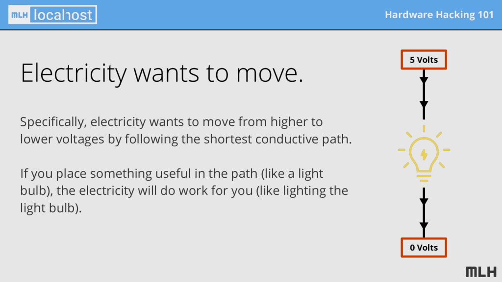
to lower voltages by following the shortest conductive path. If you place something useful in the path (like a light bulb), the electricity will do work for you (like lighting the light bulb). 5 Volts 0 Volts
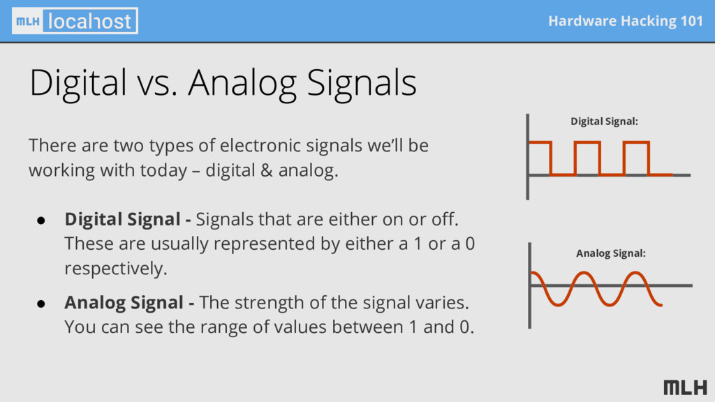
we’ll be working with today – digital & analog. • Digital Signal - Signals that are either on or off. These are usually represented by either a 1 or a 0 respectively. • Analog Signal - The strength of the signal varies. You can see the range of values between 1 and 0. Digital Signal: Analog Signal:
has a lot on it. There are 3 main parts you’ll need to know about today... 1 2 3 USB port Power & ground pins Digital I/O pins 1 2 3 Analog Input pins 4 4
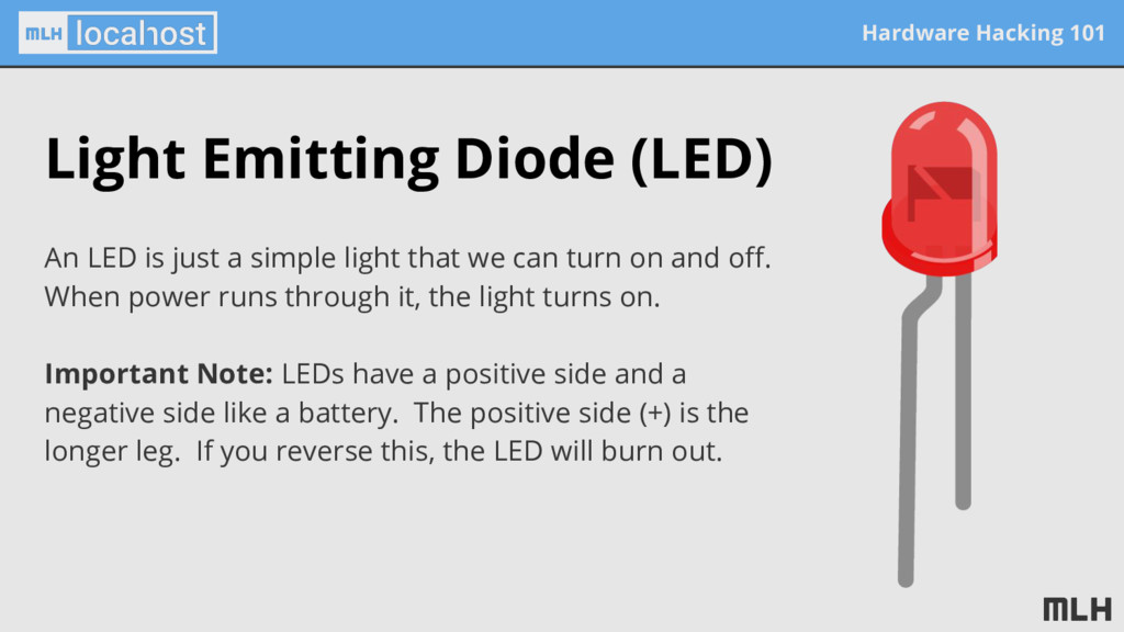
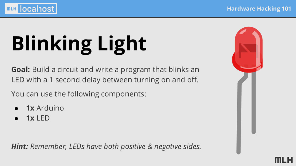
just a simple light that we can turn on and off. When power runs through it, the light turns on. Important Note: LEDs have a positive side and a negative side like a battery. The positive side (+) is the longer leg. If you reverse this, the LED will burn out.
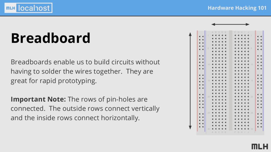
without having to solder the wires together. They are great for rapid prototyping. Important Note: The rows of pin-holes are connected. The outside rows connect vertically and the inside rows connect horizontally.
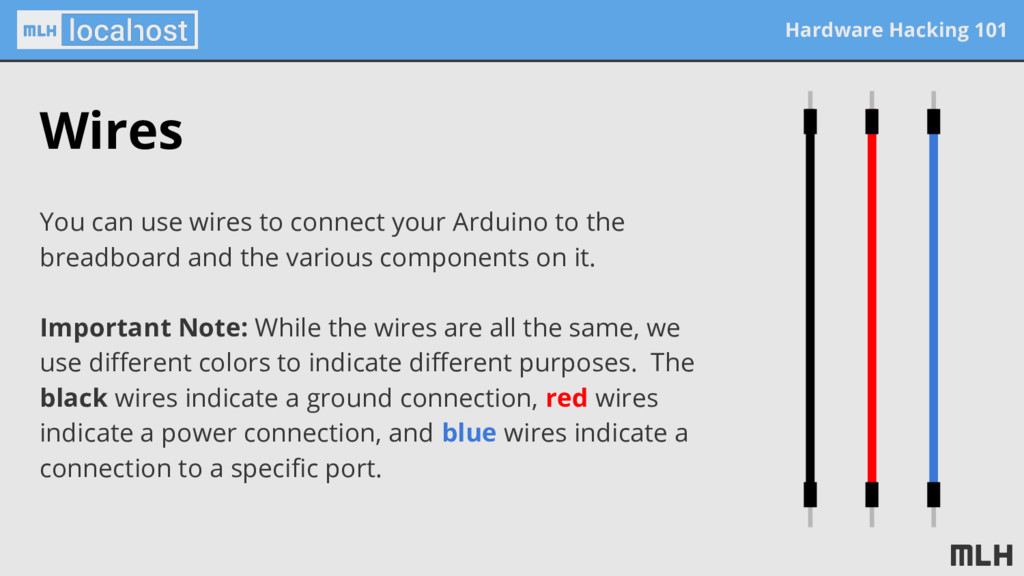
your Arduino to the breadboard and the various components on it. Important Note: While the wires are all the same, we use different colors to indicate different purposes. The black wires indicate a ground connection, red wires indicate a power connection, and blue wires indicate a connection to a specific port.
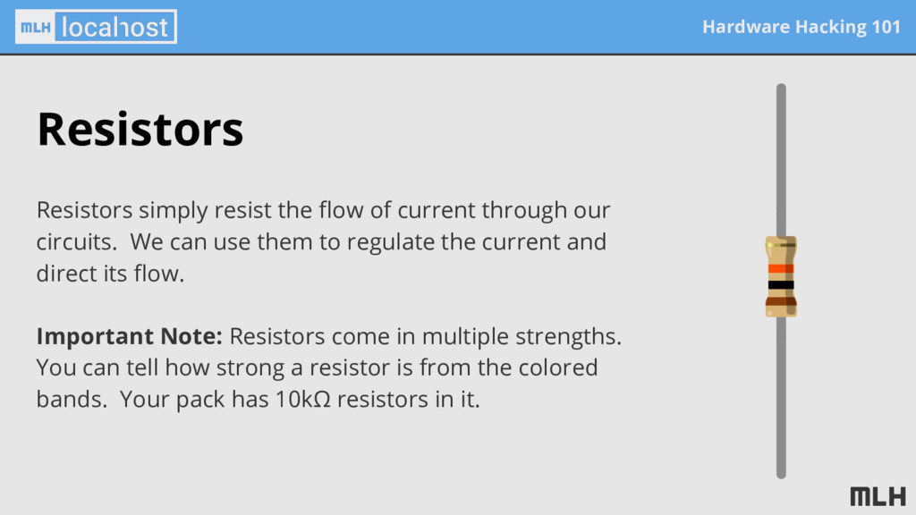
current through our circuits. We can use them to regulate the current and direct its flow. Important Note: Resistors come in multiple strengths. You can tell how strong a resistor is from the colored bands. Your pack has 10kΩ resistors in it.
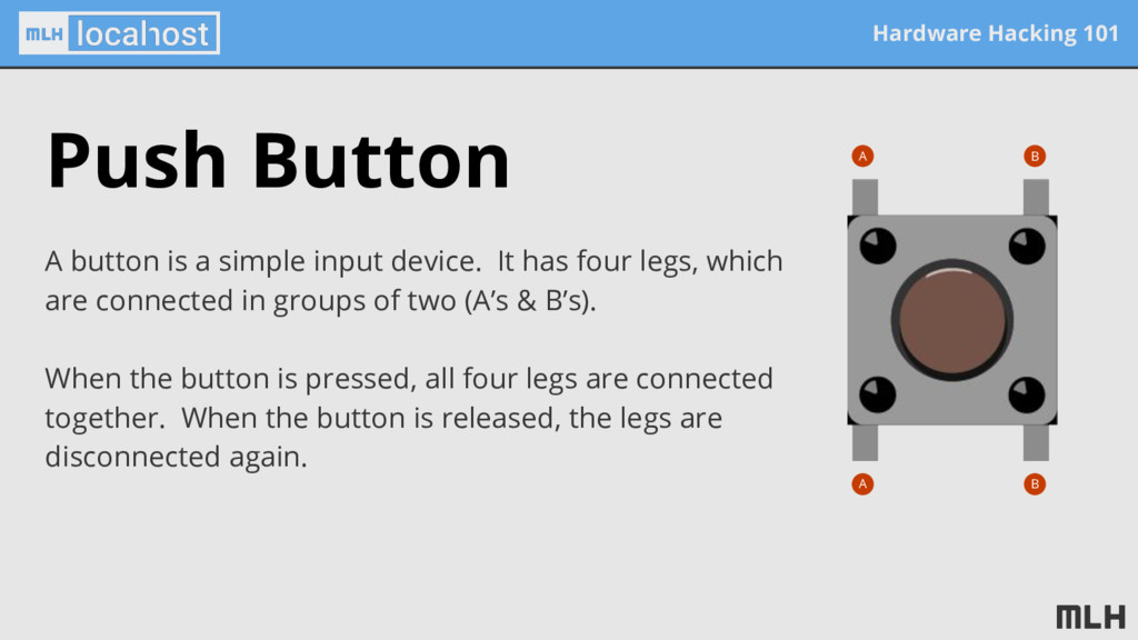
input device. It has four legs, which are connected in groups of two (A’s & B’s). When the button is pressed, all four legs are connected together. When the button is released, the legs are disconnected again. A B B A
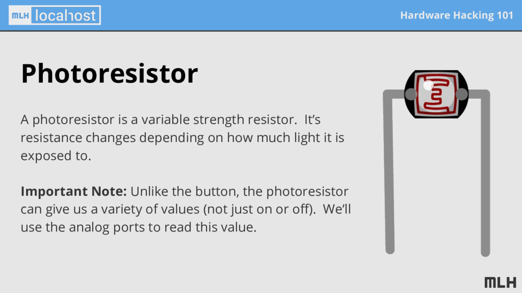
resistor. It’s resistance changes depending on how much light it is exposed to. Important Note: Unlike the button, the photoresistor can give us a variety of values (not just on or off). We’ll use the analog ports to read this value.
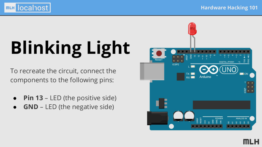
write a program that blinks an LED with a 1 second delay between turning on and off. You can use the following components: • 1x Arduino • 1x LED Hint: Remember, LEDs have both positive & negative sides.
It has two main parts: • Setup – This code is run once during startup. It sets pin 13 (the LED) as an output. • Loop – This code is run continuously. It alternates setting pin 13 (the LED) to HIGH (on) and LOW (off), waiting 1 second in between. Hint: Save some time by navigating to: int led = 13; void setup() { pinMode(led, OUTPUT); } void loop() { digitalWrite(led, HIGH); delay(1000); digitalWrite(led, LOW); delay(1000); }
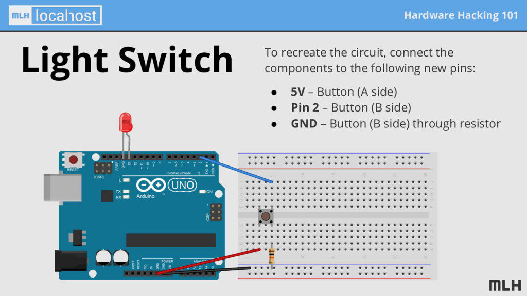
program that causes an LED to turn on when a button is pressed and off when it is released. You can use the following components: Hint: The button requires a resistor to • 1x Arduino • 1x LED • 1x Button • 3x Wire • 1x 10kΩ Resistor • 1x Breadboard Light Switch
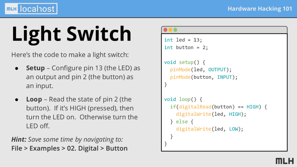
a light switch: • Setup – Configure pin 13 (the LED) as an output and pin 2 (the button) as an input. • Loop – Read the state of pin 2 (the button). If it’s HIGH (pressed), then turn the LED on. Otherwise turn the LED off. Hint: Save some time by navigating to: int led = 13; int button = 2; void setup() { pinMode(led, OUTPUT); pinMode(button, INPUT); } void loop() { if(digitalRead(button) == HIGH) { digitalWrite(led, HIGH); } else { digitalWrite(led, LOW); } }
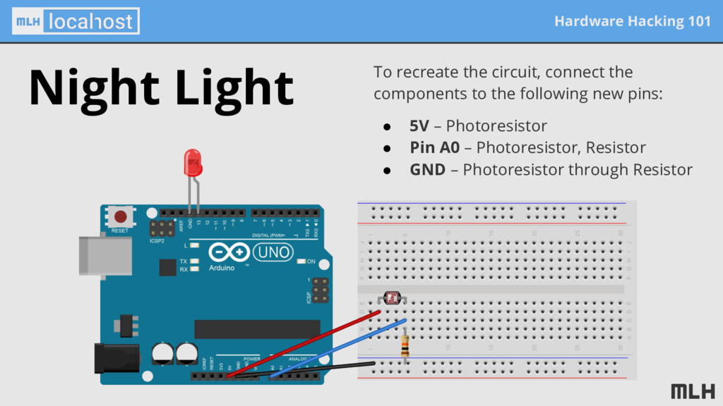
write a program that causes an LED to turn on when the room is dark and off when it is light. You can use the following components: Hint: The button requires a resistor to • 1x Arduino • 1x LED • 1x Photoresistor • 3x Wire • 1x 10kΩ Resistor • 1x Breadboard
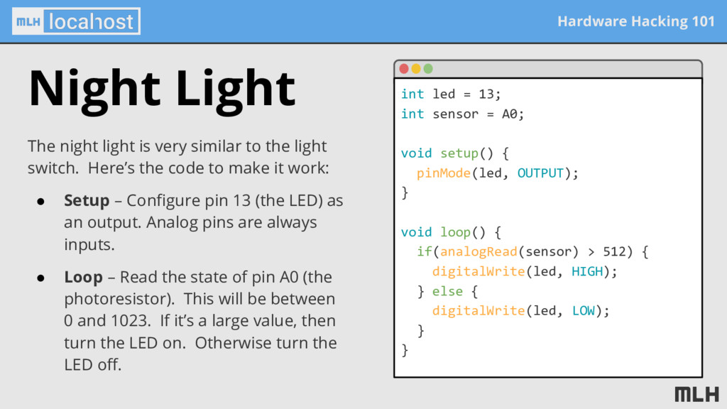
the light switch. Here’s the code to make it work: • Setup – Configure pin 13 (the LED) as an output. Analog pins are always inputs. • Loop – Read the state of pin A0 (the photoresistor). This will be between 0 and 1023. If it’s a large value, then turn the LED on. Otherwise turn the LED off. int led = 13; int sensor = A0; void setup() { pinMode(led, OUTPUT); } void loop() { if(analogRead(sensor) > 512) { digitalWrite(led, HIGH); } else { digitalWrite(led, LOW); } } Night Light
learned the basics of hardware hacking using an Arduino and some simple components. Read and assemble basic circuits Blink a light automatically Build a simple light switch
your school! MLH Localhost makes it easy for you to run fun hacker events for your local community where & when you want. We’ll train you to run the event and ship you a box with everything you need! Schedule your first event online at localhost.mlh.io
hackathon! Every year, MLH helps organize over 250 weekend-long invention competitions called “hackathons”. Show up, join a team, and bring a crazy idea to life over the course of 24 hours. Find a hackathon near you at mlh.io/events
![Hardware Hacking 101 Swift @SwiftAlphaOne [email protected]](https://files.speakerdeck.com/presentations/d0fd633f2ae34b97861e00768fa4390d/slide_1.jpg)
![Hardware Hacking 101 Thank you! @SwiftAlphaOne [email protected]](https://files.speakerdeck.com/presentations/d0fd633f2ae34b97861e00768fa4390d/slide_31.jpg)