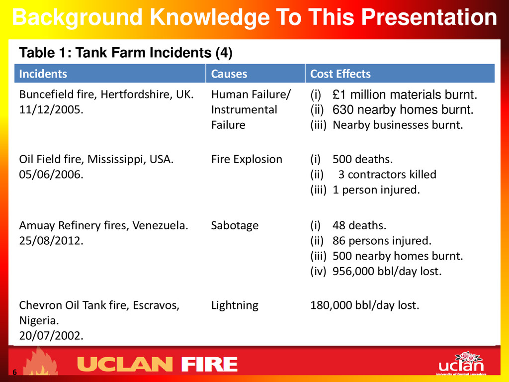
The casualties arising from fire and explosions in tank farm operations are alarming and heartbreaking and thus call for urgent remedy. In achieving this, the effect of wind on fire spread was critically investigated using CFD Simulations. The wind effect is crucial for safe tank farm operations and this depends largely on the chemicals stored and the tank capacity and the wind speed of Nigeria was employed for this research project. An explicit work of wind effect showed that as the wind speed increases, the heat release rate (HRR) decreases and the flame height decreases thereby reducing the safe tank distance (1), (2) and (3).