XAFS Experiment Instrumentation, Sample Preparation, and Experiment Design Bruce Ravel Synchrotron Science Group National Institute of Standards and Technology & Beamline for Materials Measurements National Synchrotron Light Source II SUNY Binghamton 25 October 2012 1 / 42 The XAFS Experiment
This document is copyright c 2010-2015 Bruce Ravel. This work is licensed under the Creative Commons Attribution-ShareAlike License. To view a copy of this license, visit http://creativecommons.org/licenses/by-sa/3.0/ or send a letter to Creative Commons, 559 Nathan Abbott Way, Stanford, California 94305, USA. You are free: to Share — to copy, distribute, and transmit the work to Remix — to adapt the work to make commercial use of the work Under the following conditions: Attribution – You must attribute the work in the manner specified by the author or licensor (but not in any way that suggests that they endorse you or your use of the work). Share Alike – If you alter, transform, or build upon this work, you may distribute the resulting work only under the same, similar or a compatible license. With the understanidng that: Waiver – Any of the above conditions can be waived if you get permission from the copyright holder. Public Domain – Where the work or any of its elements is in the public domain under applicable law, that status is in no way affected by the license. Other Rights – In no way are any of the following rights affected by the license: Your fair dealing or fair use rights, or other applicable copyright exceptions and limitations; The author’s moral rights; Rights other persons may have either in the work itself or in how the work is used, such as publicity or privacy rights. Notice – For any reuse or distribution, you must make clear to others the license terms of this work. This is a human-readable summary of the Legal Code (the full license). 2 / 42 The XAFS Experiment
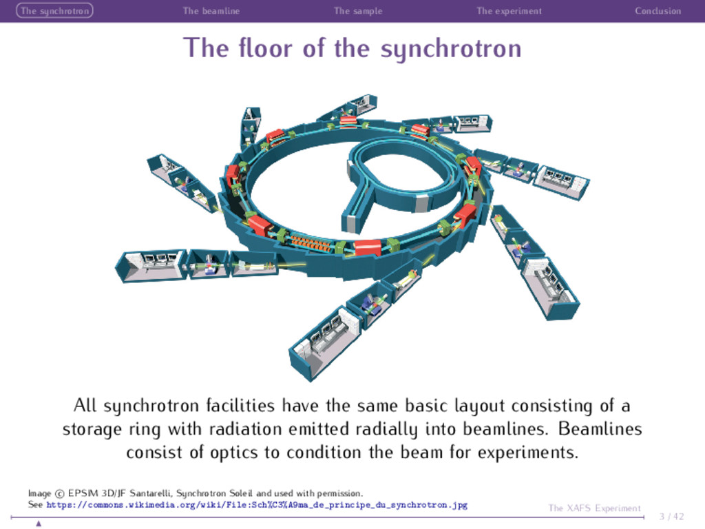
floor of the synchrotron All synchrotron facilities have the same basic layout consisting of a storage ring with radiation emitted radially into beamlines. Beamlines consist of optics to condition the beam for experiments. 3 / 42 The XAFS Experiment Image c EPSIM 3D/JF Santarelli, Synchrotron Soleil and used with permission. See https://commons.wikimedia.org/wiki/File:Sch%C3%A9ma_de_principe_du_synchrotron.jpg
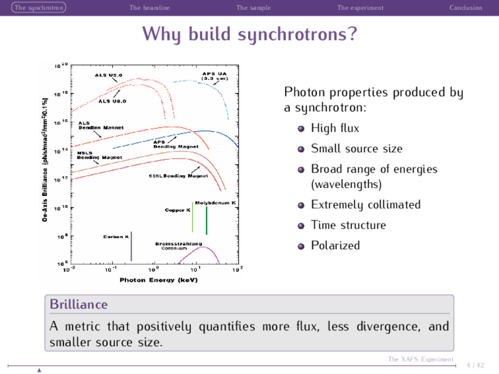
build synchrotrons? Photon properties produced by a synchrotron: High flux Small source size Broad range of energies (wavelengths) Extremely collimated Time structure Polarized Brilliance A metric that positively quantifies more flux, less divergence, and smaller source size. 4 / 42 The XAFS Experiment
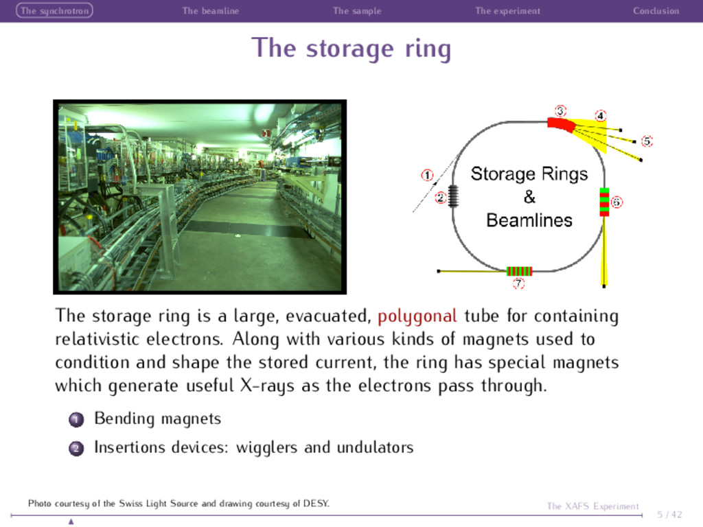
storage ring The storage ring is a large, evacuated, polygonal tube for containing relativistic electrons. Along with various kinds of magnets used to condition and shape the stored current, the ring has special magnets which generate useful X-rays as the electrons pass through. 1 Bending magnets 2 Insertions devices: wigglers and undulators 5 / 42 The XAFS Experiment Photo courtesy of the Swiss Light Source and drawing courtesy of DESY.
magnets Bend magnets serve two purposes: Steer the electrons between straight sections Generate photons for use in a beamline With relativistic electrons, the light emitted by the bend magnet is in a narrow cone. 6 / 42 The XAFS Experiment Photo and drawing courtesy of the Advanced Light Source and http://lightsources.org
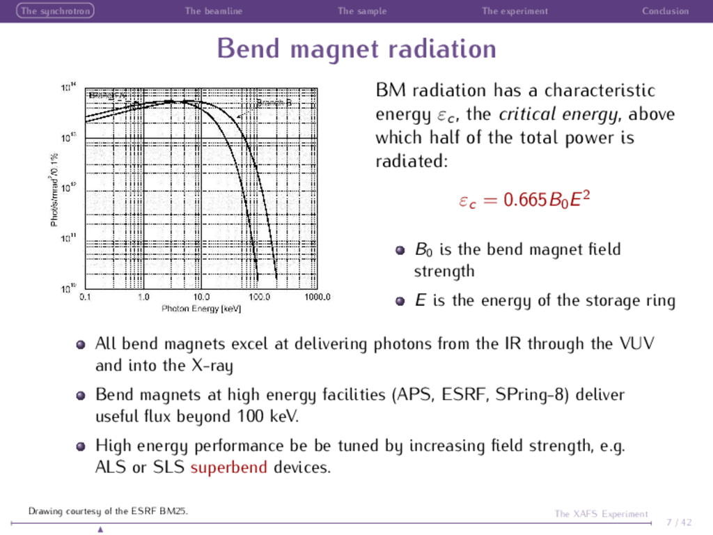
magnet radiation BM radiation has a characteristic energy εc , the critical energy, above which half of the total power is radiated: εc = 0.665B0 E2 B0 is the bend magnet field strength E is the energy of the storage ring All bend magnets excel at delivering photons from the IR through the VUV and into the X-ray Bend magnets at high energy facilities (APS, ESRF, SPring-8) deliver useful flux beyond 100 keV. High energy performance be be tuned by increasing field strength, e.g. ALS or SLS superbend devices. 7 / 42 The XAFS Experiment Drawing courtesy of the ESRF BM25.
devices Insertion devices periodic magnetic structures designed to improve upon the performance of bending magnets. They are inserted into the straight sections of the storage ring. Insertion devices in use around the world range from the enormous (APS undulator A, > 2 m, on the left) to the compact (the NSLS X25 minigap undulator, < 1 m, on the right). 8 / 42 The XAFS Experiment Photos courtesy of the APS and NSLS.
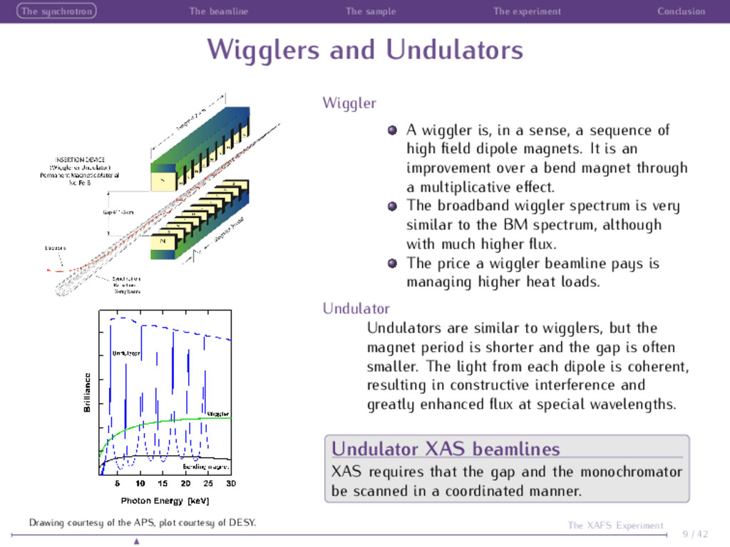
and Undulators Wiggler A wiggler is, in a sense, a sequence of high field dipole magnets. It is an improvement over a bend magnet through a multiplicative effect. The broadband wiggler spectrum is very similar to the BM spectrum, although with much higher flux. The price a wiggler beamline pays is managing higher heat loads. Undulator Undulators are similar to wigglers, but the magnet period is shorter and the gap is often smaller. The light from each dipole is coherent, resulting in constructive interference and greatly enhanced flux at special wavelengths. Undulator XAS beamlines XAS requires that the gap and the monochromator be scanned in a coordinated manner. 9 / 42 The XAFS Experiment Drawing courtesy of the APS, plot courtesy of DESY.
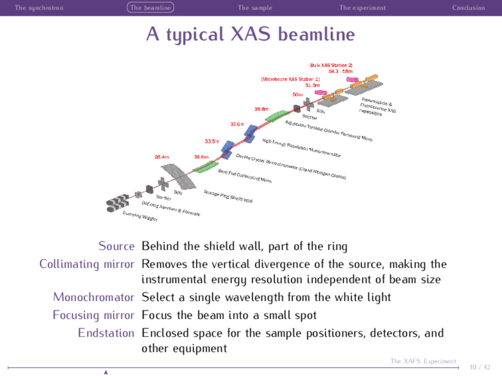
typical XAS beamline Source Behind the shield wall, part of the ring Collimating mirror Removes the vertical divergence of the source, making the instrumental energy resolution independent of beam size Monochromator Select a single wavelength from the white light Focusing mirror Focus the beam into a small spot Endstation Enclosed space for the sample positioners, detectors, and other equipment 10 / 42 The XAFS Experiment
and Focusing Mirrors Total external reflection A mirror is smooth (˚ Angstrom roughness) Si, SiO2 or other material, often coated with a metal (Ni, Pt, Rh). Focusing Parabolic curvature beam Rm = 2pq (p+q) sin θ typically km Cylindrical curvature ⊥ to beam Rs = 2pq sin θ p+q typically cm (De)Magnification M = q p Collimation q → ∞ Rm = 2p sin θ Collimation limited by source size δθ = Sv /p 11 / 42 The XAFS Experiment
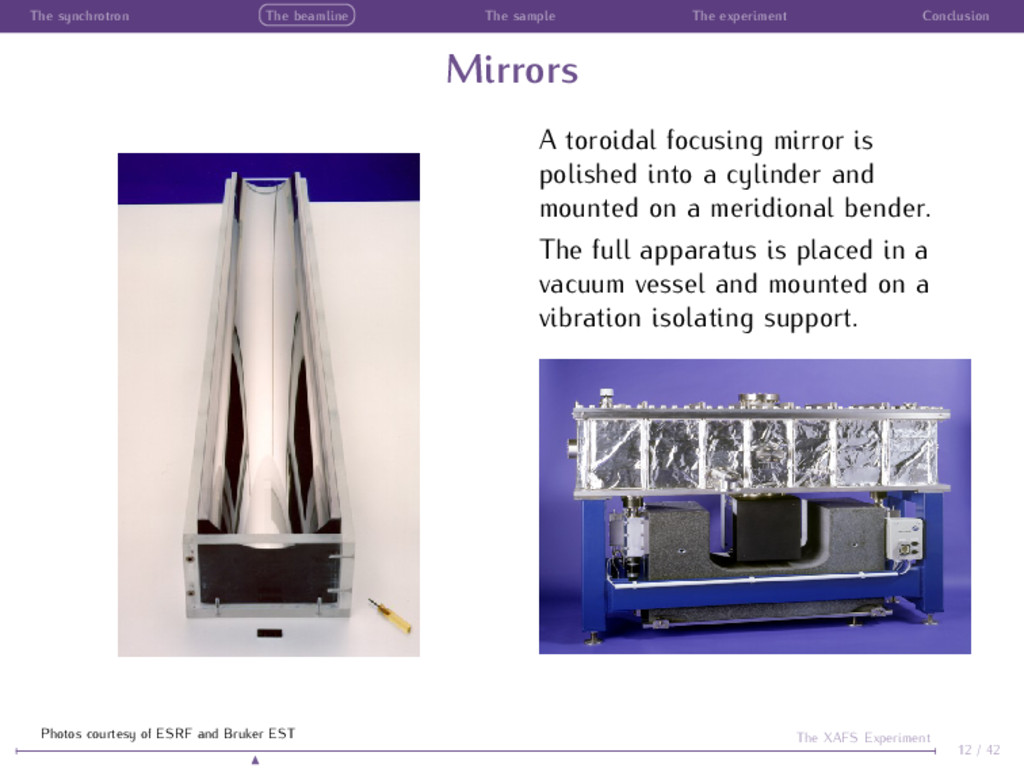
A toroidal focusing mirror is polished into a cylinder and mounted on a meridional bender. The full apparatus is placed in a vacuum vessel and mounted on a vibration isolating support. 12 / 42 The XAFS Experiment Photos courtesy of ESRF and Bruker EST
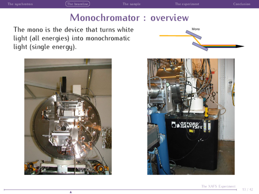
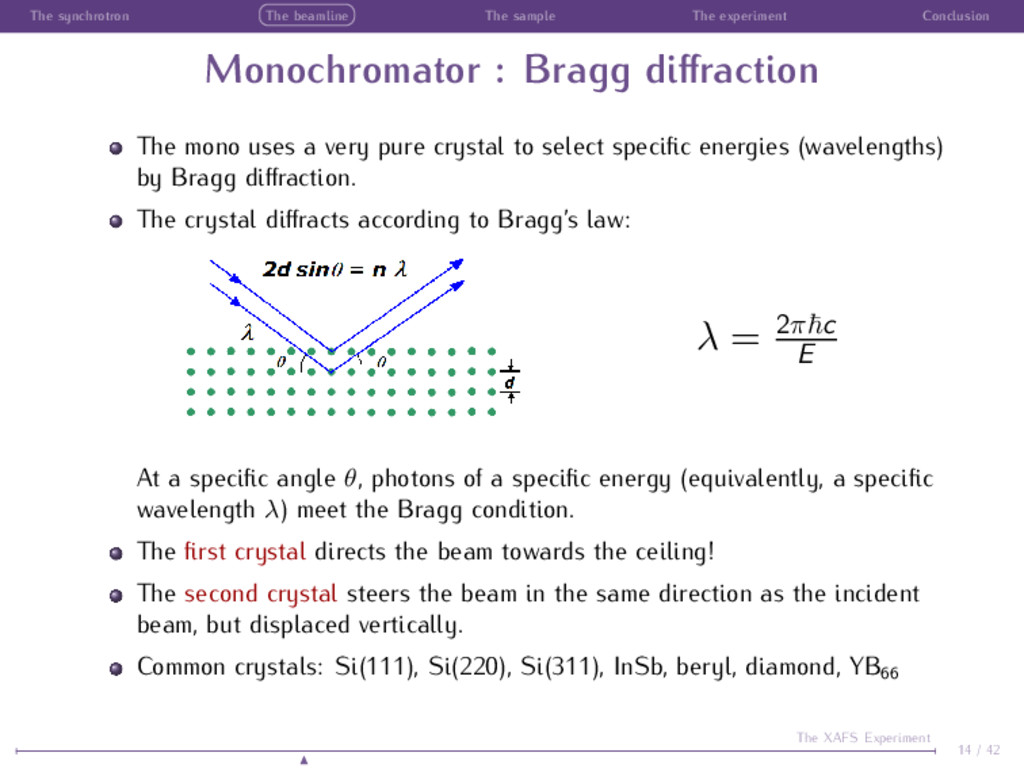
: Bragg diffraction The mono uses a very pure crystal to select specific energies (wavelengths) by Bragg diffraction. The crystal diffracts according to Bragg’s law: λ = 2π c E At a specific angle θ, photons of a specific energy (equivalently, a specific wavelength λ) meet the Bragg condition. The first crystal directs the beam towards the ceiling! The second crystal steers the beam in the same direction as the incident beam, but displaced vertically. Common crystals: Si(111), Si(220), Si(311), InSb, beryl, diamond, YB66 14 / 42 The XAFS Experiment
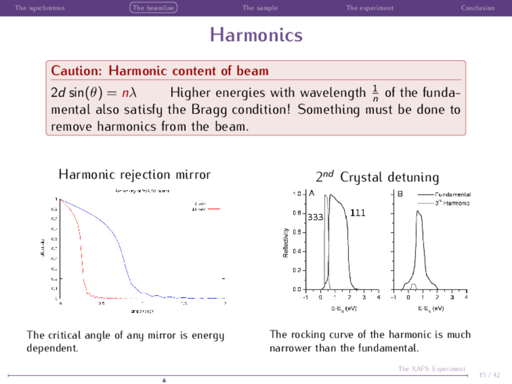
Caution: Harmonic content of beam 2d sin(θ) = nλ Higher energies with wavelength 1 n of the funda- mental also satisfy the Bragg condition! Something must be done to remove harmonics from the beam. Harmonic rejection mirror The critical angle of any mirror is energy dependent. 2nd Crystal detuning The rocking curve of the harmonic is much narrower than the fundamental. 15 / 42 The XAFS Experiment
preparation The basic rule of sample preparation Ideally, the sample is homogeneous so that every ray of light interacts identically with every part of the sample. To the extent that you are capable of doing so, you should always prepare your sample with this in mind. Really good samples include things like: Solutions and suspensions Fine powders dispersed in a binder like BN, graphite, or cellulose Uniform films Adsorbed species in uniformly dispersed biomass ... and so on ... 16 / 42 The XAFS Experiment
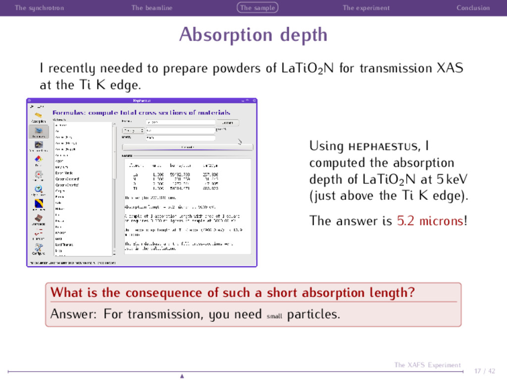
depth I recently needed to prepare powders of LaTiO2N for transmission XAS at the Ti K edge. Using , I computed the absorption depth of LaTiO2N at 5 keV (just above the Ti K edge). The answer is 5.2 microns! What is the consequence of such a short absorption length? Answer: For transmission, you need small particles. 17 / 42 The XAFS Experiment
problem with large particles If your particles are large compared to an absorption length, then your sample will look something like this: This is bad! Some regions are very thick, while other regions have gaps (or leakage). The leak- age problem distorts the your data by decreasing white line height and altering the measured σ2 of the EXAFS. Nonlin- earity in response leads to systematically noisy data. 18 / 42 The XAFS Experiment The data are from Grant Bunker’s Sample Preparation tutorial. See http://gbxafs.iit.edu/training/tutorials.html
good transmission sample 1 Particles are small compared to an absorption length. 2 Particles are homogeneously dispersed so that the sample is of uniform and appropriate thickness for the energy of the measurement. 3 The full sample (absorber + matrix) is not so thick that few (or no!) photons make it to the transmission chamber. 4 The edge step is large enough to yield high quality data. An edge step 1 is great, but anything from ∼ 0.05 to ∼ 1.5 should yield fine data. Powder samples 1 Grind powders in a mortar and pestle or otherwise prepare small powders. 2 Note that a #400 laboratory sieve has openings of 37 microns! 3 Use sedimentation or some other technique to separate the fine powders. 4 Spreading on tape and mixing with an inert binder are both good sample preparation methods. 19 / 42 The XAFS Experiment
or fluorescence? When should a sample be measured in fluorescence? If the criteria on the previous slide cannot be met, then you will likely need to measure in fluorescence. When possible, transmission usually yields superior data quality. If: your sample is large and cannot be damaged (e.g. a cultural heritage sample or anything else your collaborator expects to get back), the absorber is dilute in your sample such that you cannot obtain an edge step > 0.05 in a thin enough sample to pass light to transmission chamber, your sample is not dilute but exists in small quantities (e.g. a thin film sample), you are measuring a low-energy edge such that preparing a transmission sample is simply impossible, then you should consider fluorescence. 20 / 42 The XAFS Experiment
good fluorescence sample The best fluorescence sample is homogeneous in absorber concentra- tion and is either thin∗ or dilute. Homogeneity Inhomogeneous samples will suffer from leakage effects in fluorescence as well as in transmission, although the effect is less pronounced in fluorescence. Regardless, homogeneous samples are good samples! Diluteness Samples that are concentrated in the absorber element will be subject to self-absorption† distortions. Contaminants in soils Dilute solutions Dopants in bulks materials Organometallic compounds Constituents of plant or animal tissues Thin films ... and so on ... 21 / 42 The XAFS Experiment ∗ Compared to an absorption length. † Also known as “over-absorption.”
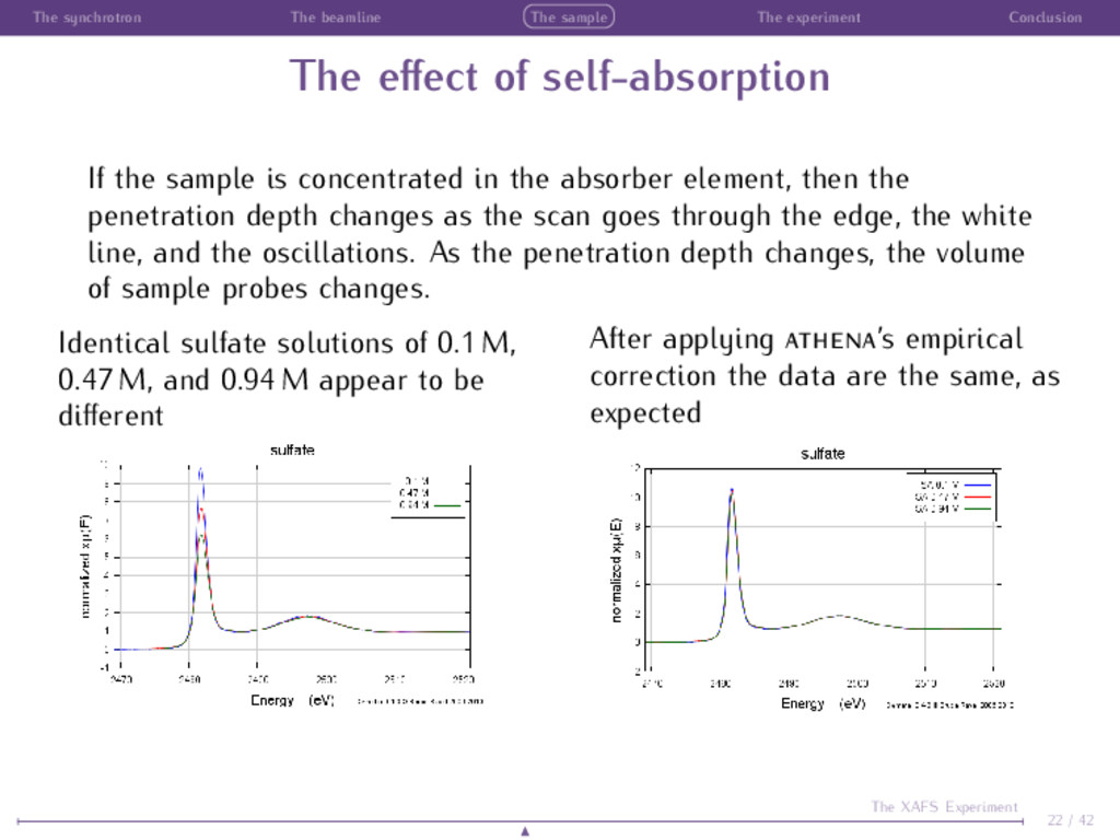
effect of self-absorption If the sample is concentrated in the absorber element, then the penetration depth changes as the scan goes through the edge, the white line, and the oscillations. As the penetration depth changes, the volume of sample probes changes. Identical sulfate solutions of 0.1 M, 0.47 M, and 0.94 M appear to be different After applying ’s empirical correction the data are the same, as expected 22 / 42 The XAFS Experiment
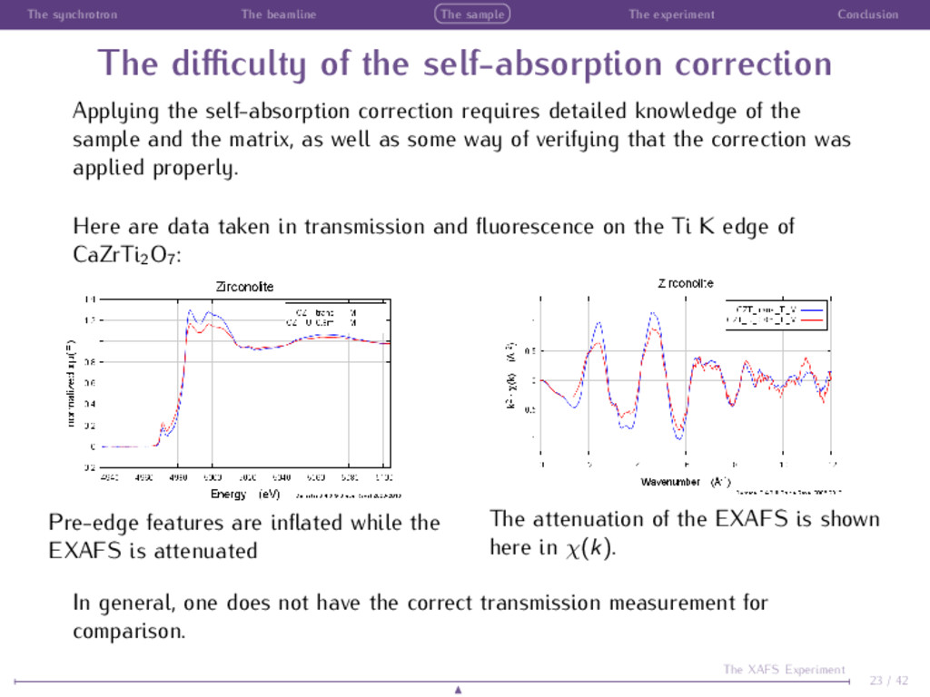
difficulty of the self-absorption correction Applying the self-absorption correction requires detailed knowledge of the sample and the matrix, as well as some way of verifying that the correction was applied properly. Here are data taken in transmission and fluorescence on the Ti K edge of CaZrTi2O7: Pre-edge features are inflated while the EXAFS is attenuated The attenuation of the EXAFS is shown here in χ(k). In general, one does not have the correct transmission measurement for comparison. 23 / 42 The XAFS Experiment
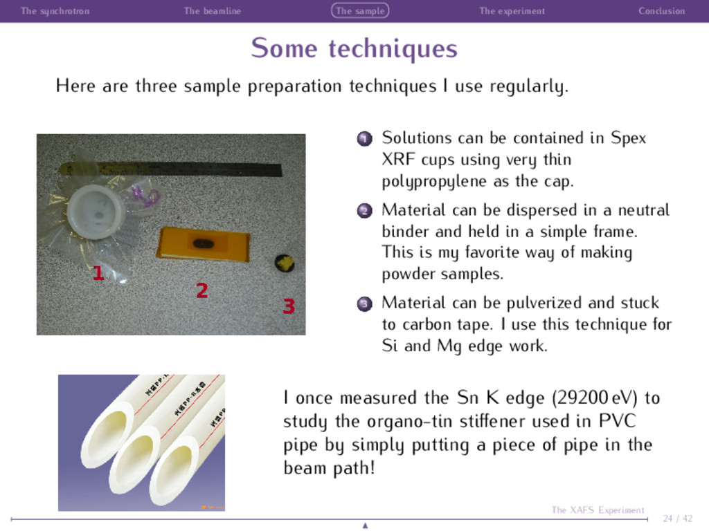
techniques Here are three sample preparation techniques I use regularly. 1 Solutions can be contained in Spex XRF cups using very thin polypropylene as the cap. 2 Material can be dispersed in a neutral binder and held in a simple frame. This is my favorite way of making powder samples. 3 Material can be pulverized and stuck to carbon tape. I use this technique for Si and Mg edge work. I once measured the Sn K edge (29200 eV) to study the organo-tin stiffener used in PVC pipe by simply putting a piece of pipe in the beam path! 24 / 42 The XAFS Experiment
a good experiment XAS is a fairly easy experiment A good result, though, requires care and planning. Choice of detectors Choice of sample conditions or environment Adequate ensemble of data Adequate statistics 25 / 42 The XAFS Experiment
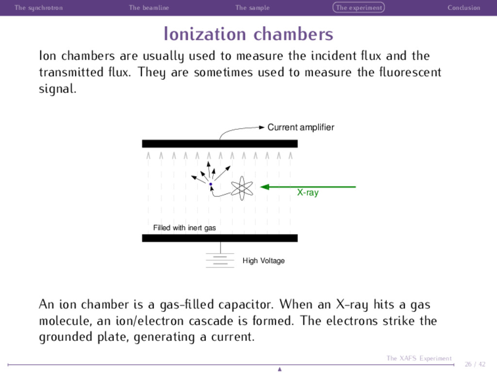
chambers Ion chambers are usually used to measure the incident flux and the transmitted flux. They are sometimes used to measure the fluorescent signal. Xray Current amplifier High Voltage Filled with inert gas An ion chamber is a gas-filled capacitor. When an X-ray hits a gas molecule, an ion/electron cascade is formed. The electrons strike the grounded plate, generating a current. 26 / 42 The XAFS Experiment
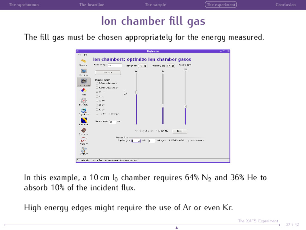
chamber fill gas The fill gas must be chosen appropriately for the energy measured. In this example, a 10 cm I0 chamber requires 64% N2 and 36% He to absorb 10% of the incident flux. High energy edges might require the use of Ar or even Kr. 27 / 42 The XAFS Experiment
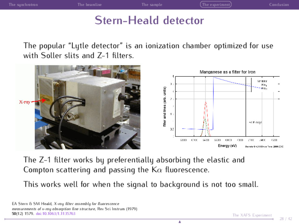
detector The popular “Lytle detector” is an ionization chamber optimized for use with Soller slits and Z-1 filters. The Z-1 filter works by preferentially absorbing the elastic and Compton scattering and passing the Kα fluorescence. This works well for when the signal to background is not too small. 28 / 42 The XAFS Experiment EA Stern & SM Heald, X-ray filter assembly for fluorescence measurements of x-ray absorption fine structure, Rev Sci Instrum (1979) 50(12) 1579. doi:10.1063/1.1135763
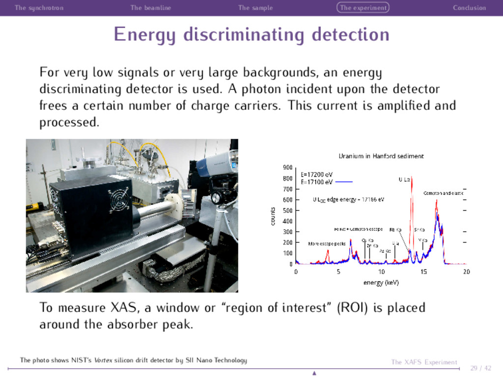
discriminating detection For very low signals or very large backgrounds, an energy discriminating detector is used. A photon incident upon the detector frees a certain number of charge carriers. This current is amplified and processed. To measure XAS, a window or “region of interest” (ROI) is placed around the absorber peak. 29 / 42 The XAFS Experiment The photo shows NIST’s Vortex silicon drift detector by SII Nano Technology
environment XAS is usually capable of measuring your sample very close to the “proper” state. Because X-rays are deeply penetrating, an XAS experiment can be made in an appropriate sample environment. Because XAS is relatively insensitive to the sample matrix, XAS can be measured on almost anything. Because XAS is element specific, minimal sample preparation is required. Sequential extraction, dessication, and other chemistry-altering procedures can be avoided. Because XAS has no dependence on symmetry or periodicity, XAS can be measured on matter in all states. Always remember A good experiment is a highly relevant experiment! 30 / 42 The XAFS Experiment
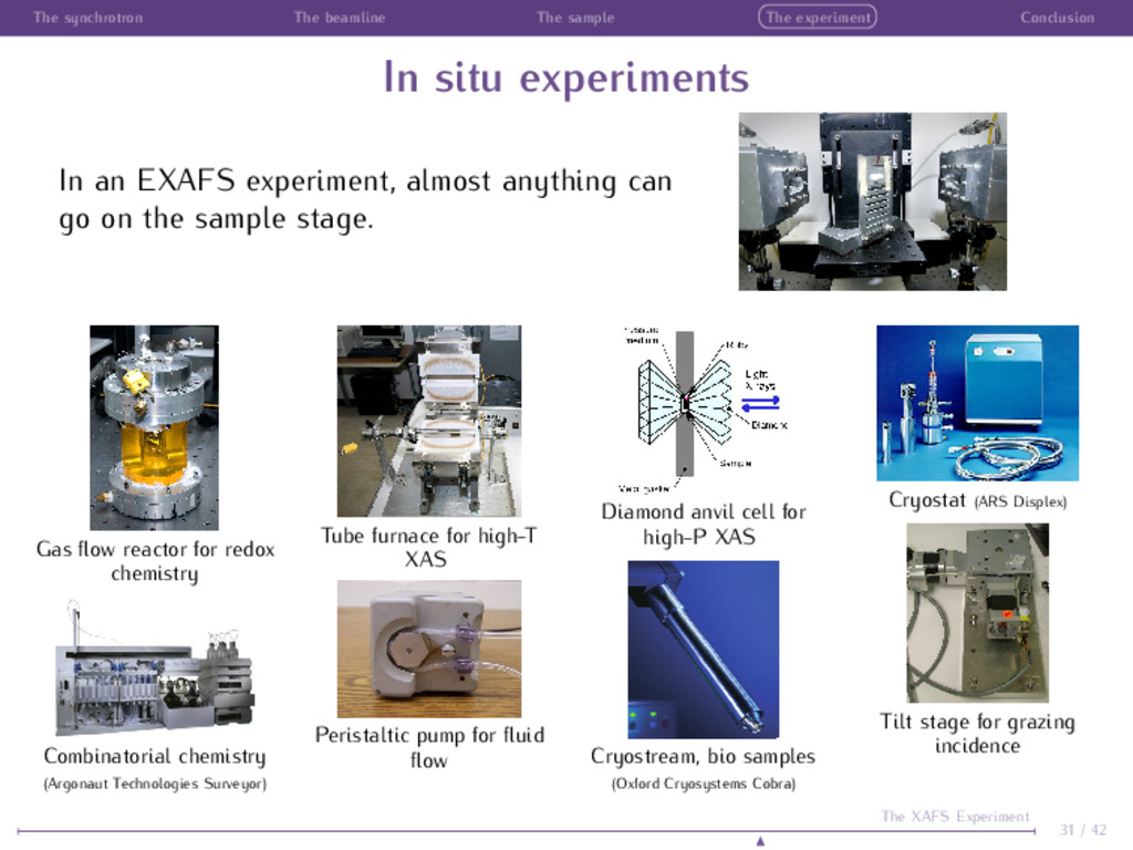
situ experiments In an EXAFS experiment, almost anything can go on the sample stage. Gas flow reactor for redox chemistry Combinatorial chemistry (Argonaut Technologies Surveyor) Tube furnace for high-T XAS Peristaltic pump for fluid flow Diamond anvil cell for high-P XAS Cryostream, bio samples (Oxford Cryosystems Cobra) Cryostat (ARS Displex) Tilt stage for grazing incidence 31 / 42 The XAFS Experiment
of samples I’ll say this again: A good experiment is a highly relevant experiment! When planning your experiment, you must plan to measure enough samples that you can fully interpret your data and fully understand the scientific problem you are studying. This means you must: measure enough standards measure enough different samples 32 / 42 The XAFS Experiment
of standards How many standards should I measure? Answer: All of them! Well, OK ... you can’t measure everything. But your standard library should be extensive. XANES analysis techniques rely upon completeness of standards libraries Even EXAFS analysis benefits by access to good standards. It is often useful to measure and analyze a known standard as a sanity check on the experimental set-up and on the data analysis tools and procedures 33 / 42 The XAFS Experiment
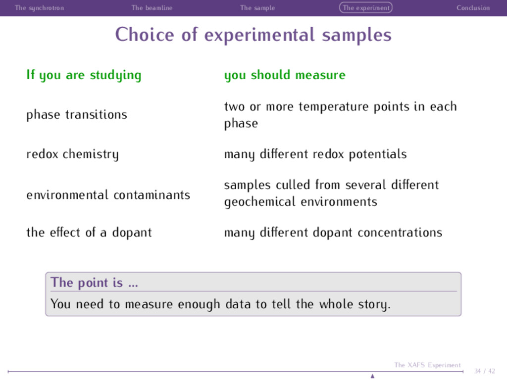
of experimental samples If you are studying you should measure phase transitions two or more temperature points in each phase redox chemistry many different redox potentials environmental contaminants samples culled from several different geochemical environments the effect of a dopant many different dopant concentrations The point is ... You need to measure enough data to tell the whole story. 34 / 42 The XAFS Experiment
much is enough data? In any experiment, there is a tension between time and data quality, between measuring enough samples and measuring each sample well enough. The central limit theorem always works! Ga K edge EXAFS from a 53 ˚ A Ga0.26In0.74As alloy grown on an InP(001) substrate recorded at glancing-incidence. A single scan of ∼ 20 minutes (black) is compared to the merged EXAFS (blue) from the same sample after 4 days of data collection on NSLS X23A2. If a sample is difficult but important, it is worth spending time on. Measurement statistics Data dominated by statistical noise will get better as you measure longer 4× more data → 2× better data. Data affected by systematic error cannot be improved by measuring longer. 35 / 42 The XAFS Experiment J.C. Woicik et al., Appl. Phys. Lett. 73:9 (1998) 1269
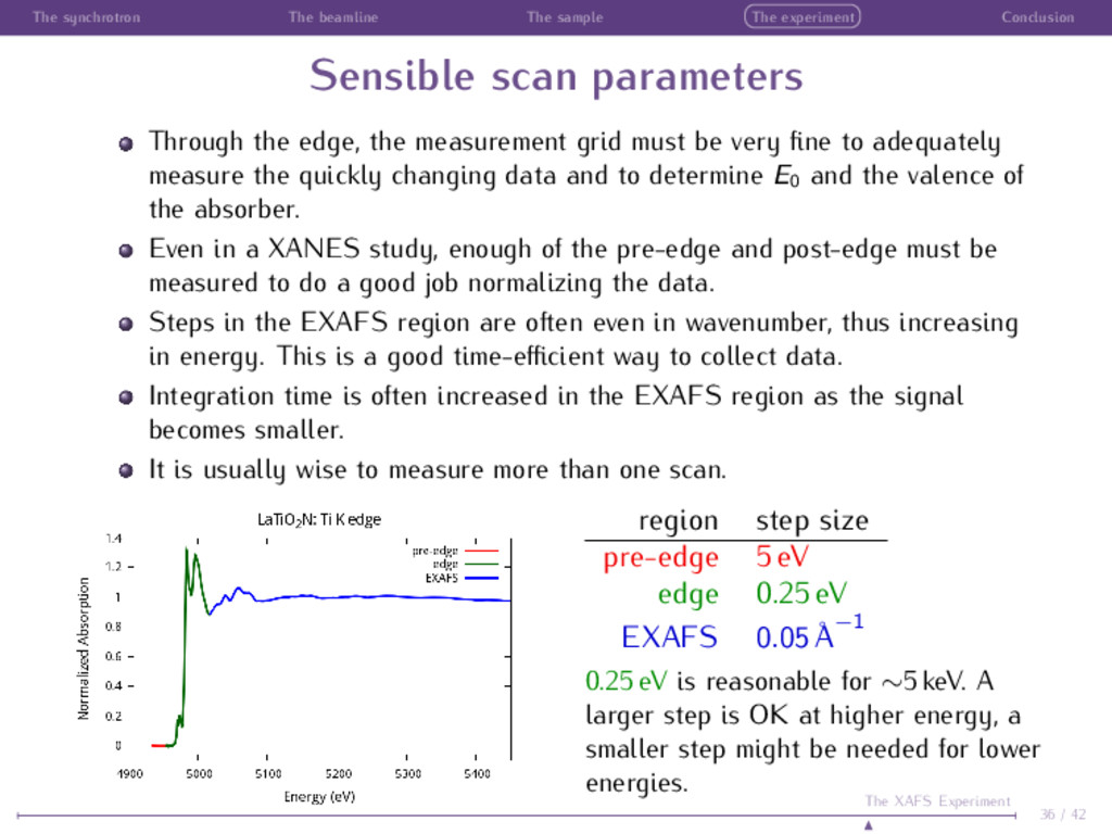
scan parameters Through the edge, the measurement grid must be very fine to adequately measure the quickly changing data and to determine E0 and the valence of the absorber. Even in a XANES study, enough of the pre-edge and post-edge must be measured to do a good job normalizing the data. Steps in the EXAFS region are often even in wavenumber, thus increasing in energy. This is a good time-efficient way to collect data. Integration time is often increased in the EXAFS region as the signal becomes smaller. It is usually wise to measure more than one scan. region step size pre-edge 5 eV edge 0.25 eV EXAFS 0.05 ˚ A −1 0.25 eV is reasonable for ∼5 keV. A larger step is OK at higher energy, a smaller step might be needed for lower energies. 36 / 42 The XAFS Experiment
many scans is enough? “It is usually wise to measure more than one scan.” Fine. So how many is enough? There is no simple answer to that question and it is the reason that even the best beamline automation still requires a human being to be involved with the experiment. If you plan for one scan and something goes wrong, you have no data. If you plan for two scans and something goes wrong, you don’t know which one is right. If you plan for three scans and your data is still noisy, you don’t have enough data. It takes data to determine how much data you need. You need good enough statistics such that the data you intend to analyze is large compared to the level of noise. So, measure enough data such that the statistical noise becomes small compared to χ(k). 37 / 42 The XAFS Experiment
take-home message 1 Prepare your samples well 2 Think hard about how to measure your data 3 Measure beautiful data It’s that simple! 38 / 42 The XAFS Experiment
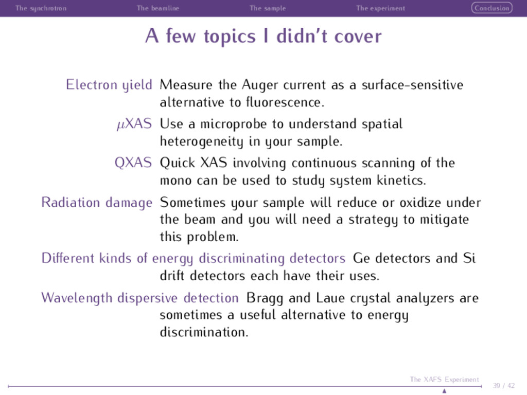
few topics I didn’t cover Electron yield Measure the Auger current as a surface-sensitive alternative to fluorescence. µXAS Use a microprobe to understand spatial heterogeneity in your sample. QXAS Quick XAS involving continuous scanning of the mono can be used to study system kinetics. Radiation damage Sometimes your sample will reduce or oxidize under the beam and you will need a strategy to mitigate this problem. Different kinds of energy discriminating detectors Ge detectors and Si drift detectors each have their uses. Wavelength dispersive detection Bragg and Laue crystal analyzers are sometimes a useful alternative to energy discrimination. 39 / 42 The XAFS Experiment
http://xafs.org: Community edited site with training materials, job postings, links to software, etc. http://xafs.org/Tutorials: Links to presentations, papers, and collections of training materials by experts from around the world. http://www.nsls.bnl.gov/users/access/modules/xafs/: Flash-based, multimedia training course from NSLS. http://cars9.uchicago.edu/ifeffit/: Homepage for , , and , including FAQ and documentation. http://millenia.cars.aps.anl.gov/mailman/listinfo/ifeffit/: mailing list, the place to go with questions about XAS, the software, the theory, the experiment, etc. Adam and I regularly answer questions there, as do lots of other familiar XAS names. A recent XAS survey by Shelly Kelly, Dean Hesterberg, and myself can be found on Google Books starting at page 387: http://books.google.com/books?id=Lqh6mYoKjdQC Grant Bunker’s recently published “Introduction to XAFS” is excellent and can be found on Amazon. 40 / 42 The XAFS Experiment
Many photos taken from lightsources.org; Wikimedia Commons; the websites of NSLS, APS, CLS, DESY and ESRF; and from the websites of instrument manufacturers. Some information was cribbed from a presentation by Steve Heald Unless otherwise acknowledged, all data was measured by me or is included as an example with the source code. The Beamer L ATEX class and Sylvain Bouvaret’s progressbar theme were used to prepare this document. 41 / 42 The XAFS Experiment