Upgrade to Pro — share decks privately, control downloads, hide ads and more …

Caterpillar_Cat_D6K2_TRACK-TYPE_TRACTOR__Prefix...

dcfv
May 21, 2024
3

 Caterpillar_Cat_D6K2_TRACK-TYPE_TRACTOR__Prefix_MP7__Service_Repair_Manual__MP700001_and_up_.pdf

dcfv

May 21, 2024
Tweet

More Decks by dcfv

Transcript

  1. Shutdown SIS Previous Screen Product: TRACK-TYPE TRACTOR Model: D6K2 TRACK-TYPE

    TRACTOR MP7 Configuration: D6K Track-Type Tractor MP700001-UP (MACHINE) POWERED BY C7.1 Disassembly and Assembly C7.1 Engines Media Number -UENR0633-19 Publication Date -01/07/2015 Date Updated -29/10/2018 i05292323 Gear Group (Front) - Remove and Install SMCS - 1206-010 Removal Procedure Table 1 Required Tools Tool Part Number Part Description Qty A(1) 9U-6198 Crankshaft Turning Tool 1 A(2) 9U-7336 Housing 1 5P-7305 Engine Turning Tool 1 B 230-6284 Timing Pin (Camshaft) 1 C 136-4632 Timing Pin (Crankshaft) 1 268-1966 Adapter 1 D 298-5564 T40 Torx Socket 1 (1) The Crankshaft Turning Tool is used on the front pulley. (2) This Tool is used in the aperture for the electric starting motor. Start By: a. Remove the front cover. Refer to Disassembly and Assembly, "Front Cover - Remove and Install" for the correct procedure. b. Remove the valve mechanism cover. Refer to Disassembly and Assembly, "Valve Mechanism Cover - Remove and Install" for the correct procedure. NOTICE
  2. Keep all parts clean from contaminants. Contaminants may cause rapid

    wear and shortened component life. NOTICE Care must be taken to ensure that fluids are contained during performance of inspection, maintenance, testing, adjusting and repair of the product. Be prepared to collect the fluid with suitable containers before opening any compartment or disassembling any component containing fluids. Dispose of all fluids according to local regulations and mandates. Note: Either Tooling (A) can be used. Use the Tooling that is most suitable. Care must be taken in order to ensure that the fuel injection pump timing is not lost during the removal of the front gear group. Carefully follow the procedure in order to remove the gear group. Illustration 1 g01992076
  3. 1. Remove plug (2) from the cylinder block. Remove O-ring

    seal (1) from the plug. 2. Use Tooling (A) in order to rotate the crankshaft so that number one piston is at top dead center on the compression stroke. Refer to System Operation, Testing and Adjusting, "Finding Top Center Position for No.1 Piston" for the correct procedure. 3. Install Tooling (C) through Hole (W) in order to lock the crankshaft. Illustration 2 g03383026 4. Loosen nuts (4) on all rocker arms (5). Use Tooling (D) in order to loosen adjusters (3) on all rocker arms (5) until all valves are fully closed. Note: Failure to ensure that ALL adjusters are fully unscrewed can result in contact between the valves and pistons.
  4. Illustration 3 g03383038 5. Install Tooling (B) through Hole (X)

    in camshaft gear (7) into the front housing. Use Tooling (B) in order to lock the camshaft in the correct position. Refer to System Operation, Testing and Adjusting, "Finding Top Center Position for No.1 Piston" for the correct procedure.
  5. Illustration 4 g03383040 Alignment of timing marks 6. Mark gear

    (7), gear (8), and gear (9) in order to show alignment. Refer to Illustration 4. Note: Identification will ensure that the gears can be installed in the original alignment. 7. Remove Tooling (B) and Tooling (C). 8. Remove fuel pump gear (9). Refer to Disassembly and Assembly, "Fuel Pump Gear - Remove and Install" for the correct procedure. 9. Remove camshaft gear (7). Refer to Disassembly and Assembly, "Camshaft Gear - Remove and Install" for the correct procedure. 10. Remove idler gear (8). Refer to Disassembly and Assembly, "Idler Gear - Remove and Install" for the correct procedure.
  6. https://www.aservicemanualpdf.com/ My Dear Friend! Thank you very much for visiting.

    Full manual if required, please enter the following URL into your browser. https://www.aservicemanualpdf.com/
  7. Installation Procedure Table 2 Required Tools Tool Part Number Part

    Description Qty B 230-6284 Timing Pin (Camshaft) 1 C 136-4632 Timing Pin (Crankshaft) 1 268-1966 Adapter 1 D 298-5564 T40 Torx Socket 1 E 8T-5096 Dial Indicator Gp 1 - Magnetic Base and Stand 1 F 235-0032 Valve Lash Gauge Gp 1 NOTICE Keep all parts clean from contaminants. Contaminants may cause rapid wear and shortened component life. 1. Ensure that number one piston is at top dead center on the compression stroke. Refer to System Operation, Testing and Adjusting, "Finding Top Center for No. 1 Piston" for the correct procedure.
  8. Illustration 5 g02085993 2. If necessary, install Tooling (C) into

    Hole (W) in the cylinder block. Use Tooling (C) in order to lock the crankshaft in the correct position. Refer to System Operation, Testing and Adjusting, "Finding Top Center Position for No.1 Piston" for the correct procedure. Note: Do not use excessive force to install Tooling (C). Do not use Tooling (C) to hold the crankshaft during repairs. 3. Ensure that all of the components of the front gear group are clean and free from wear and damage. If necessary, replace any components that are worn or damaged.
  9. Illustration 6 g03383116 4. Install camshaft gear (7). Loosely install

    bolt (11) and washer (10) for the camshaft gear. Refer to Disassembly and Assembly, "Camshaft Gear - Remove and Install" for the correct procedure.
  10. Illustration 7 g03383038 5. Install Tooling (B) through Hole (X)

    in camshaft gear (7) into the front housing.
  11. Illustration 9 g03383040 Alignment of timing marks 6. Install idler

    gear (8). Refer to Disassembly and Assembly, "Idler Gear - Remove and Install". Check the end play of the idler gear. Refer to Specifications, "Gear Group (Front)" and refer to Disassembly and Assembly, "Idler Gear - Remove and Install" for the correct procedure. 7. Install fuel pump gear (9). Refer to Disassembly and Assembly, "Fuel Pump Gear - Remove and Install" for the correct procedure. 8. Ensure that the timing marks on gear (7), gear (8), and gear (9) are in alignment. Refer to Illustration 9.
  12. Illustration 10 g03383656 9. Remove Tooling (B) and Tooling (C).

    Illustration 11 g02353396 10. When a 8.8 Graded bolt (11) is installed. Tighten the bolt to a torque of 95 N·m (70 lb ft).
  13. When a 10.9 Graded bolt (11) is installed. Tighten the

    bolt to a torque of 120 N·m (89 lb ft). 11. Check the end play of the camshaft gear. Refer to Specifications, "Camshaft" for more information. Illustration 12 g03383658 12. Use Tooling (E) in order to measure the backlash for gear (7), gear (8), and gear (9). Refer to Specifications, "Gear Group (Front)" for more information. 13. Lubricate each gear with clean lubricating engine oil.
  14. Illustration 13 g03383660 14. Use Tooling (F) in order to

    check the valve lash. Refer to System Operation, Testing and Adjusting, "Engine Valve Lash - Inspect/Adjust". If necessary, use Tooling (F) and Tooling (D) to adjust the valve lash. Refer to System Operation, Testing and Adjusting, "Engine Valve Lash - Inspect/Adjust" for the correct procedure.
  15. Illustration 14 g01992076 15. Install a new O-ring seal (1)

    to plug (2). Install the plug into Hole (W) in the cylinder block. Tighten plug (2) to a torque of 21 N·m (186 lb in). End By: a. Install the front cover. Refer to Disassembly and Assembly, "Front Cover - Remove and Install" for the correct procedure. b. Install the valve mechanism cover. Refer to Disassembly and Assembly, "Valve Mechanism Cover - Remove and Install" for the correct procedure. Copyright 1993 - 2021 Caterpillar Inc. All Rights Reserved. Private Network For SIS Licensees. Thu Oct 7 01:28:34 UTC+0800 2021
  16. Shutdown SIS Previous Screen Product: TRACK-TYPE TRACTOR Model: D6K2 TRACK-TYPE

    TRACTOR MP7 Configuration: D6K Track-Type Tractor MP700001-UP (MACHINE) POWERED BY C7.1 Disassembly and Assembly C7.1 Engines Media Number -UENR0633-19 Publication Date -01/07/2015 Date Updated -29/10/2018 i05292337 Idler Gear - Remove SMCS - 1206-011 Removal Procedure Table 1 Required Tools Tool Part Number Part Description Qty A 230-6284 Timing Pin (Camshaft) 1 B 136-4632 Timing Pin (Crankshaft) 1 268-1966 Adapter 1 C 298-5564 T40 Torx Socket 1 Start By: a. Remove the front cover. Refer to Disassembly and Assembly, "Front Cover - Remove and Install" for the correct procedure. b. Remove the valve mechanism cover. Refer to Disassembly and Assembly, "Valve Mechanism Cover - Remove and Install" for the correct procedure. Note: Care must be taken in order to ensure that the fuel injection pump timing is not lost during the removal of the idler gear. Carefully follow the procedure in order to remove the fuel pump gear. NOTICE Keep all parts clean from contaminants.
  17. Illustration 2 g03414038 1. Remove plug (2) from the cylinder

    block and remove O-ring seal (1) from the plug. 2. Rotate the crankshaft so that number one piston is at top dead center on the compression stroke. Refer to System Operation, Testing and Adjusting, "Finding Top Center Position for No.1 Piston" for the correct procedure. 3. Install Tooling (B) into Hole (Y) in the cylinder block. Use Tooling (B) in order to lock the crankshaft in the correct position. Note: Do not use excessive force to install Tooling (B). Do not use Tooling (B) to hold the crankshaft during repairs. 4. Install Tooling (A) into Hole (X) in camshaft gear (3). Use Tooling (A) in order to lock the camshaft in the correct position. 5. Mark gear (3), gear (4), and gear (5) in order to show alignment. Refer to Illustration 2.
  18. Illustration 3 g03378317 6. Loosen nuts (7) on all rocker

    arms (8). Use Tooling (C) in order to loosen adjusters (6) on all rocker arms (8). Unscrew adjusters (6) on all rocker arms (8) until all valves are fully closed. Note: Failure to ensure that ALL adjusters are fully unscrewed can result in contact between the valves and pistons.
  19. Illustration 5 g03414044 7. Mark plate (9) in order to

    show orientation. Note: Identification will ensure that the plate can be installed in the original orientation. 8. Remove bolts (10). 9. Remove plate (9). 10. Remove the assembly of idler gear (3). 11. Remove hub (11) from idler gear (3). Copyright 1993 - 2021 Caterpillar Inc. All Rights Reserved. Private Network For SIS Licensees. Thu Oct 7 01:29:30 UTC+0800 2021
  20. Shutdown SIS Previous Screen Product: TRACK-TYPE TRACTOR Model: D6K2 TRACK-TYPE

    TRACTOR MP7 Configuration: D6K Track-Type Tractor MP700001-UP (MACHINE) POWERED BY C7.1 Disassembly and Assembly C7.1 Engines Media Number -UENR0633-19 Publication Date -01/07/2015 Date Updated -29/10/2018 i05292335 Idler Gear - Install SMCS - 1206-012 Installation Procedure Table 1 Required Tools Tool Part Number Part Description Qty A 230-6284 Timing Pin (Camshaft) 1 B 136-4632 Timing Pin (Crankshaft) 1 268-1966 Adapter 1 C 298-5564 T40 Torx Socket 1 D 235-0032 Valve Lash Gauge Gp 1 E 8T-5096 Dial Indicator Gp 1 - Magnetic Base and Stand 1 NOTICE Keep all parts clean from contaminants. Contaminants may cause rapid wear and shortened component life.
  21. Illustration 2 g03414057 1. Ensure that Tooling (B) is installed

    in Hole (Y) in the cylinder block. Use Tooling (B) in order to lock the crankshaft in the correct Position. Refer to System Operation, Testing and Adjusting, "Finding Top Center Position for No.1 Piston" for the correct procedure. 2. Ensure that Tooling (A) is installed into Hole (X) in camshaft gear (3).
  22. Please write to us. Our email: [email protected] Please go to

    the homepage to get the full manual, or other brand PDF manuals. Home Site: aservicemanualpdf.com
  23. Thank you very much for your reading. Please Click Here.

    Then Get COMPLETE MANUAL. NO WAITING NOTE: If there is no response to click on the link above, please download the PDF document first and then click on it.
  24. Illustration 5 g03414061 3. Clean idler gear (3) and inspect

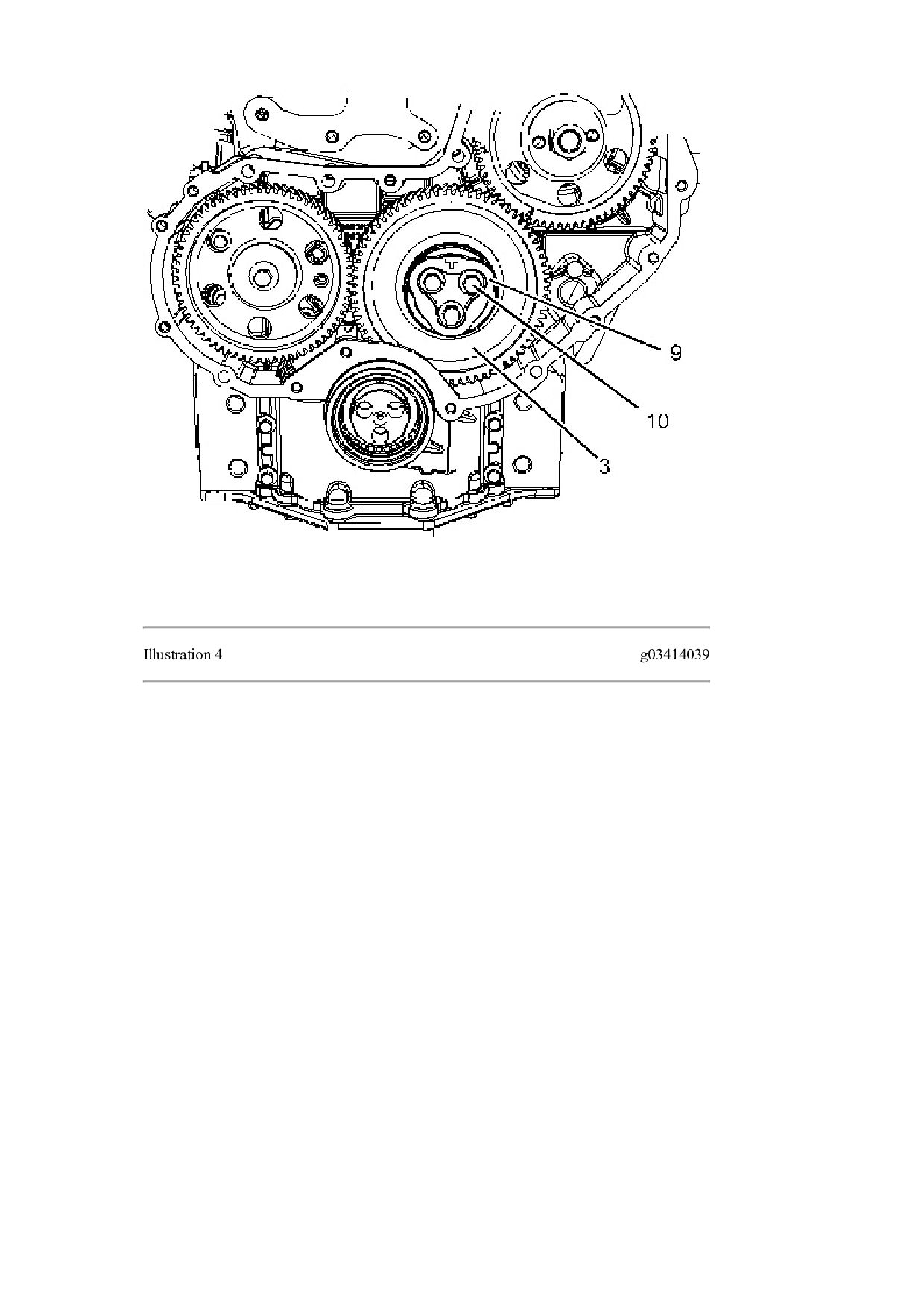
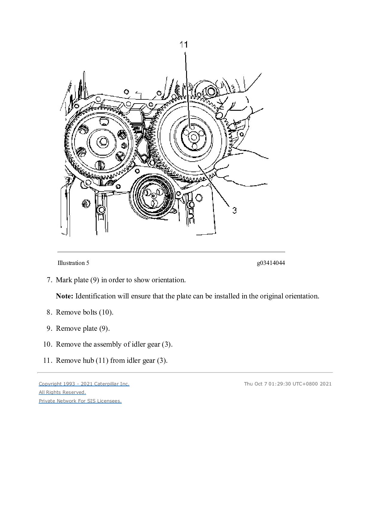
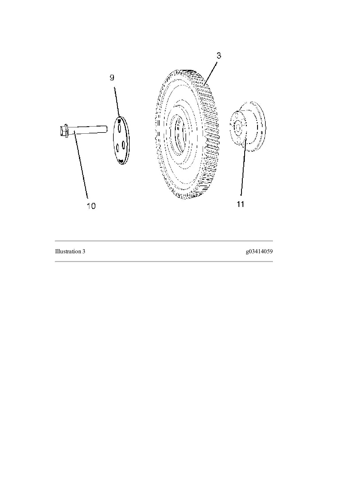
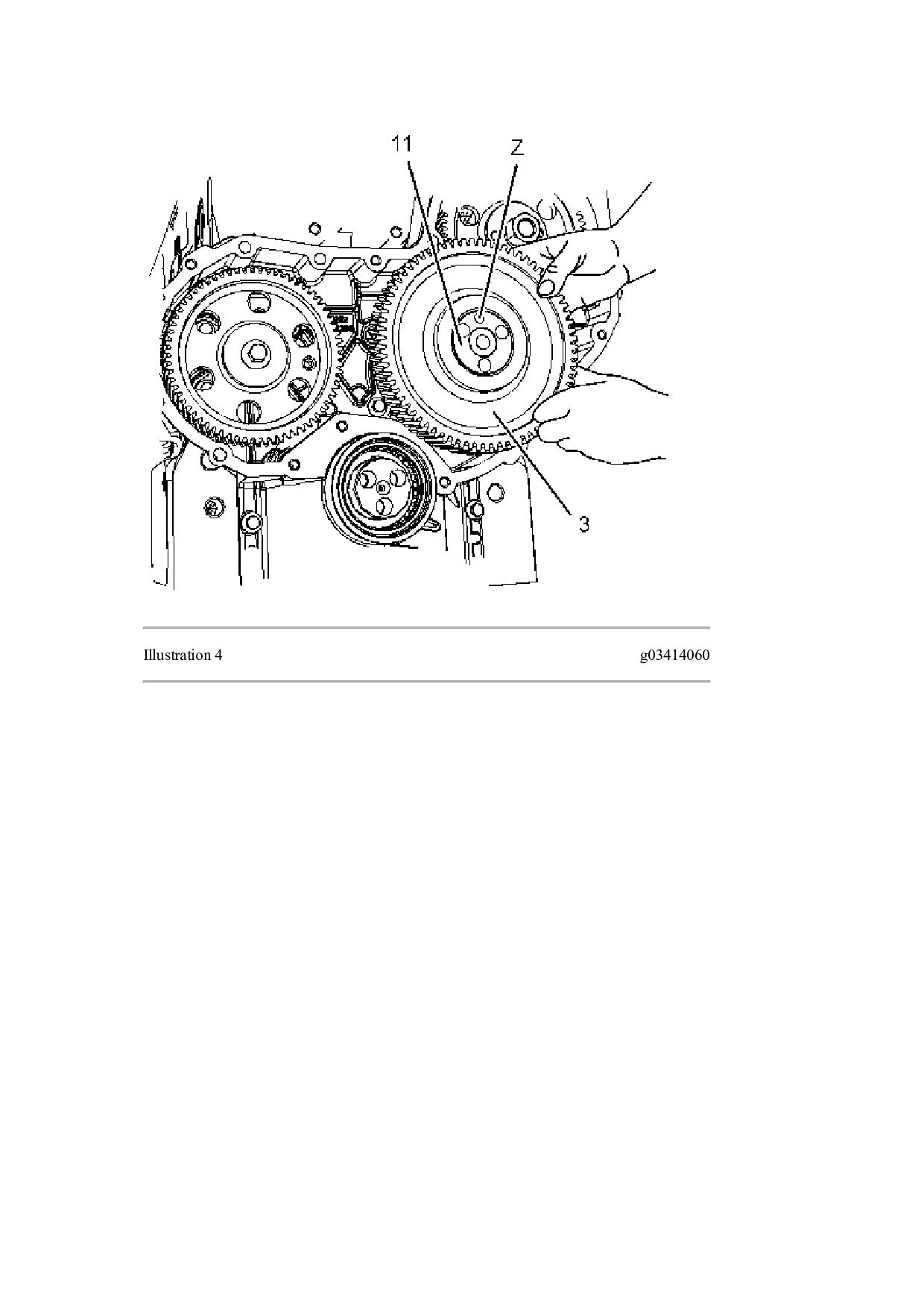
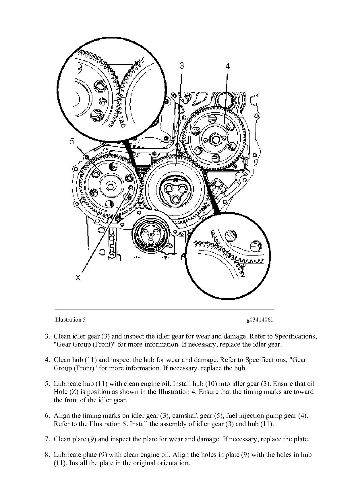
    the idler gear for wear and damage. Refer to Specifications, "Gear Group (Front)" for more information. If necessary, replace the idler gear. 4. Clean hub (11) and inspect the hub for wear and damage. Refer to Specifications, "Gear Group (Front)" for more information. If necessary, replace the hub. 5. Lubricate hub (11) with clean engine oil. Install hub (10) into idler gear (3). Ensure that oil Hole (Z) is position as shown in the Illustration 4. Ensure that the timing marks are toward the front of the idler gear. 6. Align the timing marks on idler gear (3), camshaft gear (5), fuel injection pump gear (4). Refer to the Illustration 5. Install the assembly of idler gear (3) and hub (11). 7. Clean plate (9) and inspect the plate for wear and damage. If necessary, replace the plate. 8. Lubricate plate (9) with clean engine oil. Align the holes in plate (9) with the holes in hub (11). Install the plate in the original orientation.
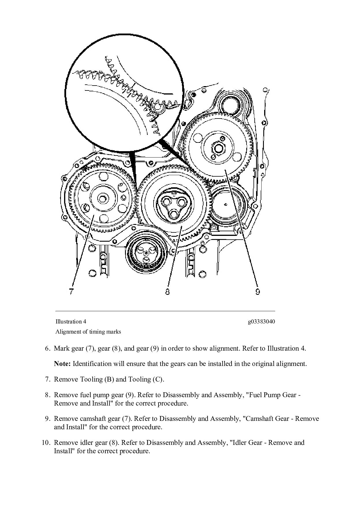
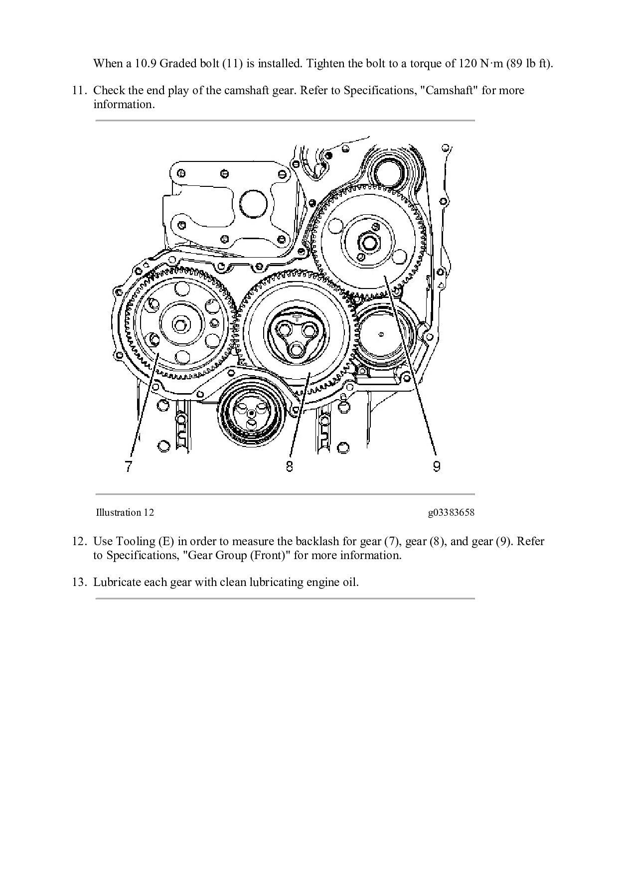
  25. Note: Ensure that the identification mark TOP is upward. 9.

    Install bolts (10) hand tight 10. Remove Tooling (A) and Tooling (B). Note: Ensure that timing marks are aligned, before removing the Tooling (A) and Tooling (B). 11. Tighten bolts (10) to a torque of 44 N·m (32 lb ft). Illustration 6 g01996554 12. Position a new O-ring seal (1) onto plug (2). Install the plug to the cylinder block and tighten the plug to a torque of 21 N·m (186 lb in). 13. Use Tooling (E) in order to check the end play for the idler gear. Refer to Specifications, "Gear Group (Front)" for more information. 14. Use Tooling (E) in order to check the backlash between the idler gear and the camshaft gear. Refer to Specifications, "Gear Group (Front)" for more information. 15. Use Tooling (E) in order to check the backlash between the idler gear and the crankshaft gear. Refer to Specifications, "Gear Group (Front)" for more information. 16. Use Tooling (E) in order to check the backlash between the idler gear and the fuel injection pump gear. Refer to Specifications, "Gear Group (Front)" for more information.
  26. https://www.aservicemanualpdf.com/ My Dear Friend! Thank you very much for visiting.

    Full manual if required, please enter the following URL into your browser. https://www.aservicemanualpdf.com/