Upgrade to Pro — share decks privately, control downloads, hide ads and more …

Caterpillar_Cat_D6N_TRACK-TYPE_TRACTOR__Prefix_...

dcrfqdcnvk
May 21, 2024
7

 Caterpillar_Cat_D6N_TRACK-TYPE_TRACTOR__Prefix_MLW__Service_Repair_Manual__MLW00001_and_up_.pdf

dcrfqdcnvk

May 21, 2024
Tweet

More Decks by dcrfqdcnvk

Transcript

  1. Shutdown SIS Previous Screen Product: TRACK-TYPE TRACTOR Model: D6N TRACK-TYPE

    TRACTOR MLW Configuration: D6N XL, LGP Differential Steering, Electrohydraulic Implement TRACK-TYPE TRACTOR MLW00001-UP (MACHINE) POWERED BY C6.6 Engine Disassembly and Assembly C6.6 Engines for Caterpillar Built Machines Media Number -KENR6081-15 Publication Date -01/03/2014 Date Updated -04/03/2014 i05000617 Engine Oil Pan Plate - Remove and Install - Aluminum Oil Pan SMCS - 1302-010 Removal Procedure Table 1 Required Tools Tool Part Number Part Description Qty A 194-3536 T40 Torx Socket 1 Start By: a. Remove the engine oil pan. Refer to Disassembly and Assembly, "Engine Oil Pan - Remove". b. Remove the flywheel housing. Refer to Disassembly and Assembly, "Flywheel Housing - Remove and Install". NOTICE Keep all parts clean from contaminants. Contaminants may cause rapid wear and shortened component life. NOTICE Care must be taken to ensure that fluids are contained during performance of inspection, maintenance, testing, adjusting and repair of the product. Be prepared to collect the fluid with suitable containers before opening any compartment or disassembling any component containing fluids. Dispose of all fluids according to local regulations and mandates.
  2. Illustration 1 g01342059 1. Remove isolating frame from the cylinder

    block. Follow steps 1.a through 1.c in order to remove the isolating frame from the cylinder block. a. Support the isolating frame (3). Use Tooling (A) to remove the torx screws (2) and (4). b. Remove the isolating frame (3) from the cylinder block. c. Remove the joint (1). Installation Procedure Table 2 Required Tools Tool Part Number Part Description Qty A 194-3536 T40 Torx Socket 1 B - Guide Stud (M8 by 100 mm) 4 C - Loctite 5900 - NOTICE Keep all parts clean from contaminants. Contaminants may cause rapid wear and shortened component life.
  3. NOTICE Care must be taken to ensure that fluids are

    contained during performance of inspection, maintenance, testing, adjusting and repair of the product. Be prepared to collect the fluid with suitable containers before opening any compartment or disassembling any component containing fluids. Dispose of all fluids according to local regulations and mandates. Illustration 2 g01342186 Typical example 1. Install Tooling (B) to Positions (X) in the cylinder block. 2. Install the isolating frame to the cylinder block. Follow Steps 2.a through 2.f in order to install the isolating frame. a. Ensure that the joint face of the cylinder block is clean and free from damage. b. Ensure that the isolating frame is clean and free from damage. If necessary, replace the isolating frame.
  4. Illustration 3 g01342058 Tooling (B) is not shown for clarity.

    c. Apply a bead of Tooling (C) to Positions (Y).
  5. https://www.aservicemanualpdf.com/ My Dear Friend! Thank you very much for visiting.

    Full manual if required, please enter the following URL into your browser. https://www.aservicemanualpdf.com/
  6. Illustration 4 g01342059 d. Position a new joint (1) onto

    the isolating frame (3). e. Align the isolating frame (3) with Tooling (B). Install the isolating frame to the cylinder block. f. Use Tooling (A) to install the two torx screws (2) and the four torx screws (4) to the isolating frame. Tighten the torx screws (2) to a torque of 22 N·m (16 lb ft). Tighten the torx screws (4) to a torque of 22 N·m (16 lb ft). End By: a. Install the engine oil pan. Refer to Disassembly and Assembly, "Engine Oil Pan - Remove". b. Install the flywheel housing. Refer to Disassembly and Assembly, "Flywheel Housing - Remove and Install". Copyright 1993 - 2021 Caterpillar Inc. All Rights Reserved. Private Network For SIS Licensees. Wed Oct 13 00:04:37 UTC+0800 2021
  7. Shutdown SIS Previous Screen Product: TRACK-TYPE TRACTOR Model: D6N TRACK-TYPE

    TRACTOR MLW Configuration: D6N XL, LGP Differential Steering, Electrohydraulic Implement TRACK-TYPE TRACTOR MLW00001-UP (MACHINE) POWERED BY C6.6 Engine Disassembly and Assembly C6.6 Engines for Caterpillar Built Machines Media Number -KENR6081-15 Publication Date -01/03/2014 Date Updated -04/03/2014 i02786914 Piston Cooling Jets - Remove and Install SMCS - 1331-010 Removal Procedure Table 1 Required Tools Tool Part Number Part Name Qty A(1) 9U-6198 Crankshaft Turning Tool 1 A(2) 9U-7336 Housing 1 5P-7305 Engine Turning Tool 1 (1) The Crankshaft Turning Tool is used on the front pulley. (2) This Tool is used in the aperture for the electric starting motor. Start By: a. Remove the engine oil pump. Refer to Disassembly and Assembly, "Engine Oil Pump - Remove". Note: Either Tooling (A) can be used. Use the Tooling that is most suitable. NOTICE Keep all parts clean from contaminants. Contaminants may cause rapid wear and shortened component life. 1. If the crankshaft is installed, use Tooling (A) to rotate the crankshaft in order to gain access to the piston cooling jet.
  8. Illustration 1 g01340939 2. Remove bolt (1) and piston cooling

    jet (2) from the cylinder block. 3. Repeat steps 1 and 2 for the remaining piston cooling jets. Installation Procedure Table 2 Required Tools Tool Part Number Part Name Qty A(1) 9U-6198 Crankshaft Turning Tool 1 A(2) 9U-7336 Housing 1 5P-7305 Engine Turning Tool 1 (1) The Crankshaft Turning Tool is used on the front pulley. (2) This Tool is used in the aperture for the electric starting motor. Note: Either Tooling (A) can be used. Use the Tooling that is most suitable. NOTICE Keep all parts clean from contaminants. Contaminants may cause rapid wear and shortened component life.
  9. Illustration 2 g01340940 1. Clean the piston cooling jets and

    inspect the piston cooling jets for damage. Ensure that the valve is free to move within each piston cooling jet. Replace any damaged piston cooling jets. The procedure for checking the alignment of the piston cooling jets is described in Specifications, "Piston Cooling Jet Alignment". 2. If the crankshaft is installed, use Tooling (A) to rotate the crankshaft in order to access the mounting flange for the piston cooling jet. 3. Position piston cooling jet (2) in the cylinder block. Install bolt (1). Tighten bolt (1) to a torque of 9 N·m (80 lb in). 4. Repeat steps 2 through 3 for the remaining piston cooling jets. End By: a. Install the engine oil pump. Refer to Disassembly and Assembly, "Engine Oil Pump - Install". Copyright 1993 - 2021 Caterpillar Inc. All Rights Reserved. Private Network For SIS Licensees. Wed Oct 13 00:05:33 UTC+0800 2021
  10. Shutdown SIS Previous Screen Product: TRACK-TYPE TRACTOR Model: D6N TRACK-TYPE

    TRACTOR MLW Configuration: D6N XL, LGP Differential Steering, Electrohydraulic Implement TRACK-TYPE TRACTOR MLW00001-UP (MACHINE) POWERED BY C6.6 Engine Disassembly and Assembly C6.6 Engines for Caterpillar Built Machines Media Number -KENR6081-15 Publication Date -01/03/2014 Date Updated -04/03/2014 i06554303 Pistons and Connecting Rods - Remove SMCS - 1225-011 Removal Procedure Table 1 Required Tools Tool Part Number Part Name Qty A(1) 9U-6198 Crankshaft Turning Tool 1 A(2) 9U-7336 Housing 1 5P-7305 Engine Turning Tool 1 B 8S-2269 Ridge Reamer 1 (1) The Crankshaft Turning Tool is used on the front pulley. (2) This Tool is used in the aperture for the electric starting motor. Start By: a. Remove the cylinder head. Refer to Disassembly and Assembly, "Cylinder Head - Remove" for the correct procedure. b. Remove the engine oil pump. Refer to Disassembly and Assembly, "Engine Oil Pump - Remove" for the correct procedure. c. Remove the piston cooling jets. Refer to Disassembly and Assembly, "Piston Cooling Jets - Remove and Install" for the correct procedure. Note: Either Tooling (A) can be used. Use the Tooling that is most suitable. NOTICE Keep all parts clean from contaminants. Contaminants may cause rapid wear and shortened component life. 1. Use Tooling (A) to rotate the crankshaft until the crank pin is at the bottom center position. 2. Use Tooling (B) to remove the carbon ridge from the top inside surface of the cylinder bore.
  11. Illustration 1 g06021015 Illustration 2 g06021018 Bolt (3a) are Torx

    Bolt (3b) are Bi-Hex 3. Two types of bolts (3a) or (3b) may be installed. 4. The connecting rod and the connecting rod cap should have an etched Number (X) on the side. The number on the connecting rod and the connecting rod cap must match. Ensure that connecting rod (1) and connecting rod cap (2) are marked for the correct location. If necessary, make a temporary mark on the connecting rod and the connecting rod cap to identify the cylinder number. Note: Do not stamp the connecting rod assembly. Stamping or punching the connecting rod assembly could cause the connecting rod to fracture. 5. Remove bolts (3) and connecting rod cap (2) from connecting rod (1).
  12. Illustration 3 g01341292 6. Carefully push piston (4) and the

    connecting rod out of the cylinder bore. Lift piston (4) out of the top of the cylinder block. Note: Do not push on the fracture split surfaces of the connecting rod as damage may result. 7. Repeat Steps 1 through 6 for the remaining pistons and connecting rods. Note: Fracture split connecting rods should not be left without the connecting rod caps installed. Temporarily install connecting rod cap (2) and bolts (3) to connecting rod (1) when the assembly is out of the engine. Ensure that the etched number on connecting rod cap matches the etched number on connecting rod . Ensure the correct orientation of the connecting rod cap . The locating tab for the upper bearing shell and the lower bearing shell should be on the same side. Tighten bolts (3) to a torque of 20 N·m (14 lb ft). Copyright 1993 - 2021 Caterpillar Inc. All Rights Reserved. Private Network For SIS Licensees. Wed Oct 13 00:06:28 UTC+0800 2021
  13. Shutdown SIS Previous Screen Product: TRACK-TYPE TRACTOR Model: D6N TRACK-TYPE

    TRACTOR MLW Configuration: D6N XL, LGP Differential Steering, Electrohydraulic Implement TRACK-TYPE TRACTOR MLW00001-UP (MACHINE) POWERED BY C6.6 Engine Disassembly and Assembly C6.6 Engines for Caterpillar Built Machines Media Number -KENR6081-15 Publication Date -01/03/2014 Date Updated -04/03/2014 i05735270 Pistons and Connecting Rods - Disassemble SMCS - 1225-015 Disassembly Procedure Table 1 Required Tools Tool Part Number Part Description Qty A 1P-1857 Retaining Ring Pliers 1 B 1U-6683 Ring Expander 1 Start By: a. Remove the pistons and the connecting rods. Refer to Disassembly and Assembly, "Piston and Connecting Rods - Remove" for the correct procedure. Note: Make a temporary mark on the components of the piston and connecting rod assembly. Making temporary marks will ensure that the components of each piston and connecting rod assembly can be reinstalled in the original cylinder. Mark the underside of the piston on the front pin boss. Do not interchange components. NOTICE Keep all parts clean from contaminants. Contaminants may cause rapid wear and shortened component life.
  14. Illustration 1 g01341306 Illustration 2 g01341307 1. Remove bolts (12)

    and connecting rod cap (11) from connecting rod (6). Discard the bolts .
  15. Note: Fracture split connecting rods should not be left without

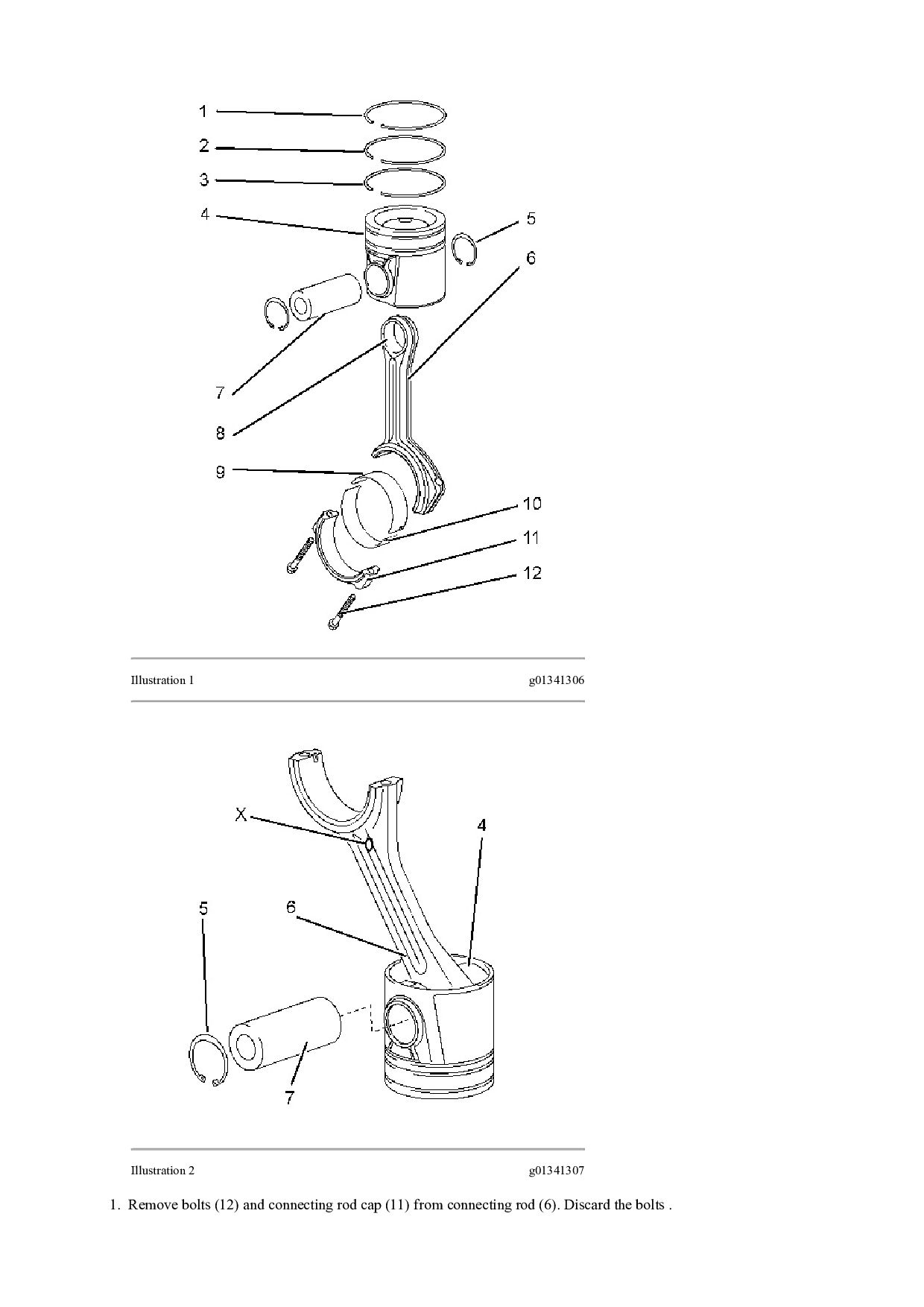
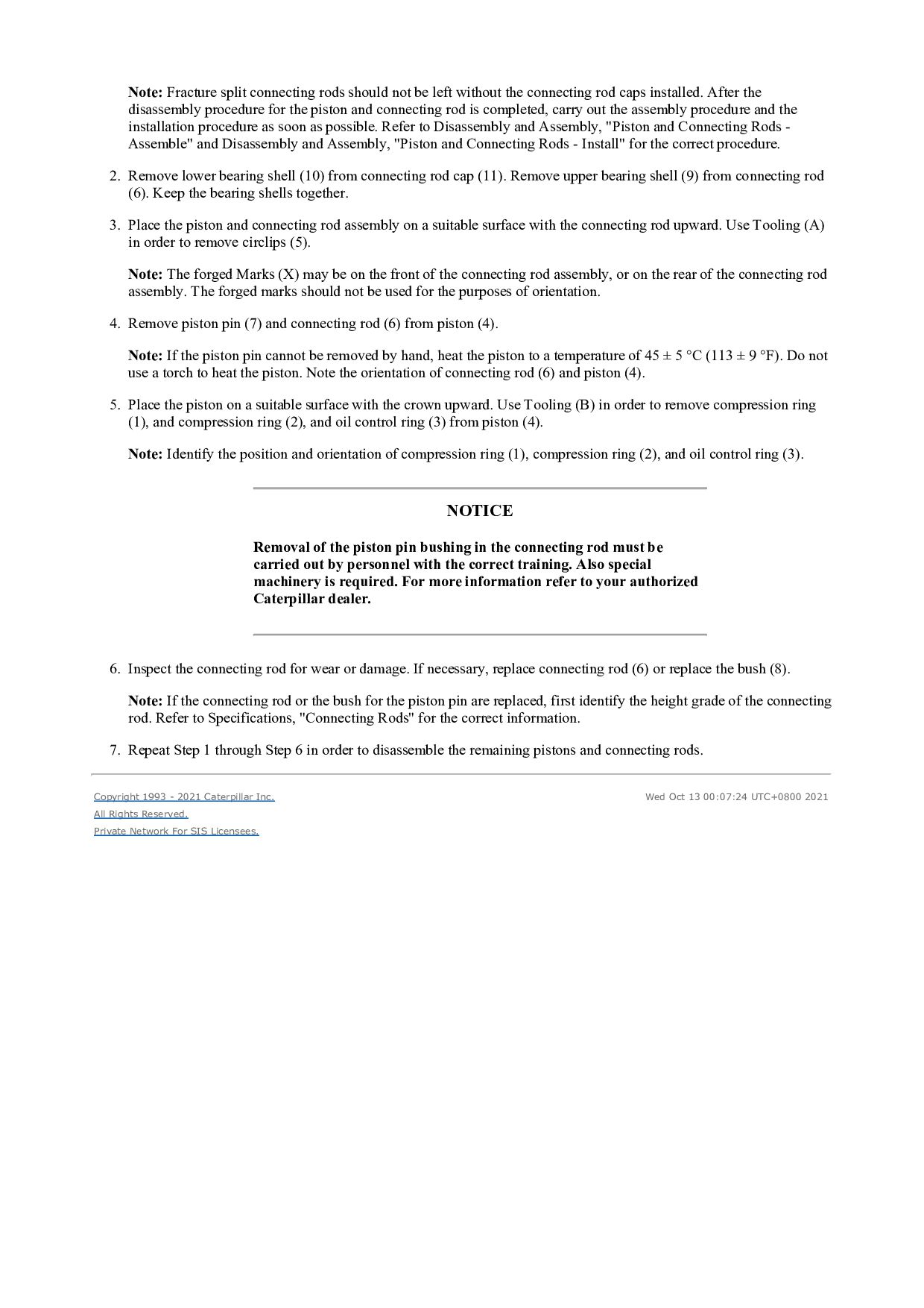
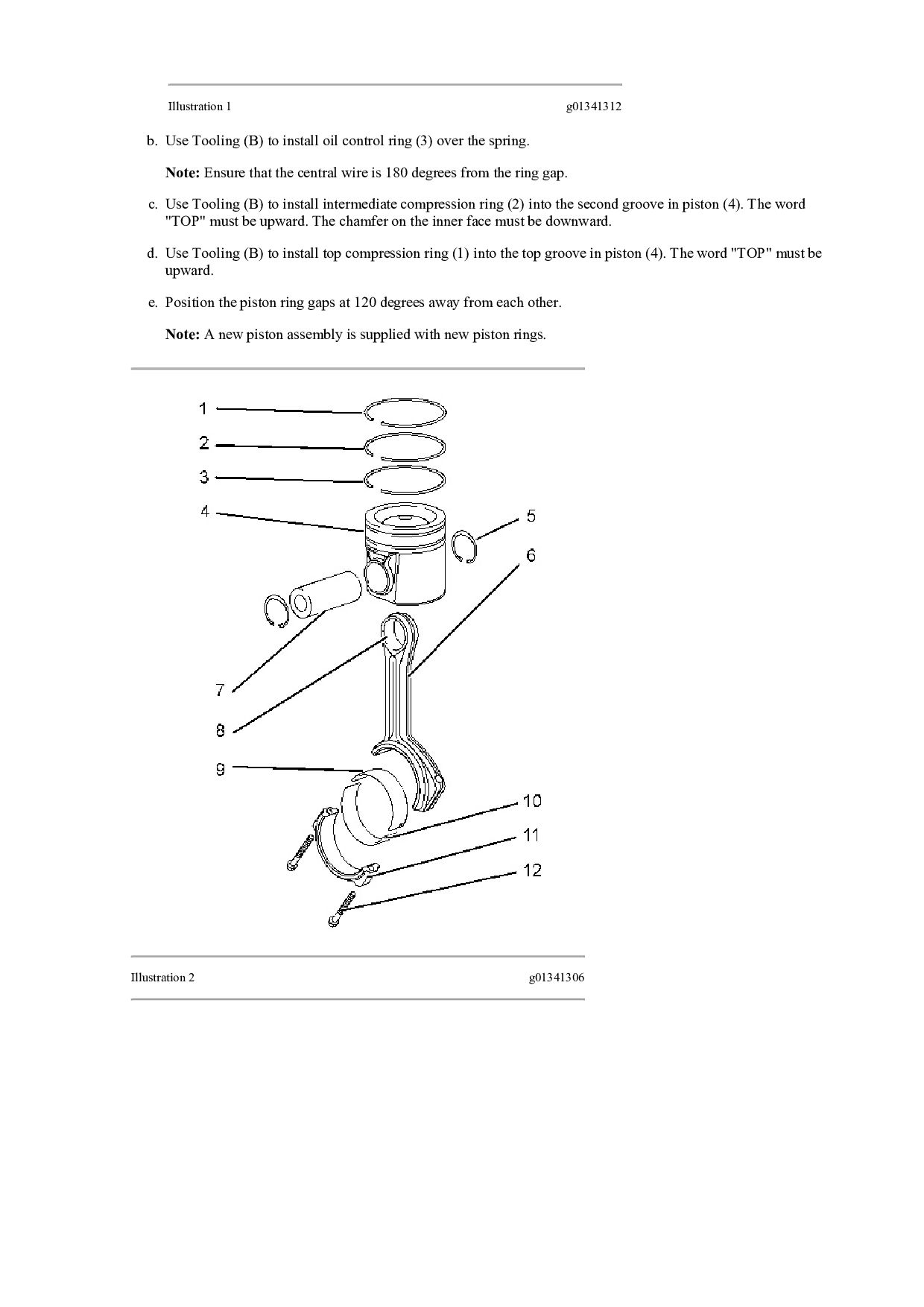
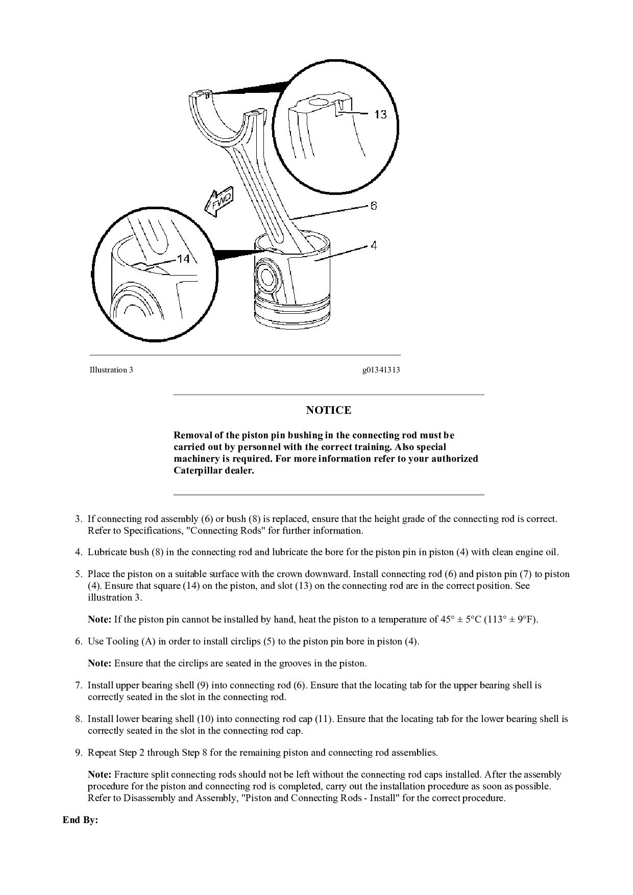
    the connecting rod caps installed. After the disassembly procedure for the piston and connecting rod is completed, carry out the assembly procedure and the installation procedure as soon as possible. Refer to Disassembly and Assembly, "Piston and Connecting Rods - Assemble" and Disassembly and Assembly, "Piston and Connecting Rods - Install" for the correct procedure. 2. Remove lower bearing shell (10) from connecting rod cap (11). Remove upper bearing shell (9) from connecting rod (6). Keep the bearing shells together. 3. Place the piston and connecting rod assembly on a suitable surface with the connecting rod upward. Use Tooling (A) in order to remove circlips (5). Note: The forged Marks (X) may be on the front of the connecting rod assembly, or on the rear of the connecting rod assembly. The forged marks should not be used for the purposes of orientation. 4. Remove piston pin (7) and connecting rod (6) from piston (4). Note: If the piston pin cannot be removed by hand, heat the piston to a temperature of 45 ± 5 °C (113 ± 9 °F). Do not use a torch to heat the piston. Note the orientation of connecting rod (6) and piston (4). 5. Place the piston on a suitable surface with the crown upward. Use Tooling (B) in order to remove compression ring (1), and compression ring (2), and oil control ring (3) from piston (4). Note: Identify the position and orientation of compression ring (1), compression ring (2), and oil control ring (3). NOTICE Removal of the piston pin bushing in the connecting rod must be carried out by personnel with the correct training. Also special machinery is required. For more information refer to your authorized Caterpillar dealer. 6. Inspect the connecting rod for wear or damage. If necessary, replace connecting rod (6) or replace the bush (8). Note: If the connecting rod or the bush for the piston pin are replaced, first identify the height grade of the connecting rod. Refer to Specifications, "Connecting Rods" for the correct information. 7. Repeat Step 1 through Step 6 in order to disassemble the remaining pistons and connecting rods. Copyright 1993 - 2021 Caterpillar Inc. All Rights Reserved. Private Network For SIS Licensees. Wed Oct 13 00:07:24 UTC+0800 2021
  16. Shutdown SIS Previous Screen Product: TRACK-TYPE TRACTOR Model: D6N TRACK-TYPE

    TRACTOR MLW Configuration: D6N XL, LGP Differential Steering, Electrohydraulic Implement TRACK-TYPE TRACTOR MLW00001-UP (MACHINE) POWERED BY C6.6 Engine Disassembly and Assembly C6.6 Engines for Caterpillar Built Machines Media Number -KENR6081-15 Publication Date -01/03/2014 Date Updated -04/03/2014 i05735272 Pistons and Connecting Rods - Assemble SMCS - 1225-016 Assembly Procedure Table 1 Required Tools Tool Part Number Part Description Qty A 1P-1857 Retaining Ring Pliers 1 B 1U-6683 Ring Expander 1 NOTICE Keep all parts clean from contaminants. Contaminants may cause rapid wear and shortened component life. 1. Ensure that all components are clean and free from wear or damage. If necessary, replace any components that are worn or damaged. 2. If the original piston is assembled, follow Step 2.a through Step 2.e in order to install the piston rings. a. Position the spring for oil control ring (3) into the oil ring groove in piston (4). The central wire must be located inside the end of the spring.
  17. Illustration 1 g01341312 b. Use Tooling (B) to install oil

    control ring (3) over the spring. Note: Ensure that the central wire is 180 degrees from the ring gap. c. Use Tooling (B) to install intermediate compression ring (2) into the second groove in piston (4). The word "TOP" must be upward. The chamfer on the inner face must be downward. d. Use Tooling (B) to install top compression ring (1) into the top groove in piston (4). The word "TOP" must be upward. e. Position the piston ring gaps at 120 degrees away from each other. Note: A new piston assembly is supplied with new piston rings. Illustration 2 g01341306
  18. Illustration 3 g01341313 NOTICE Removal of the piston pin bushing

    in the connecting rod must be carried out by personnel with the correct training. Also special machinery is required. For more information refer to your authorized Caterpillar dealer. 3. If connecting rod assembly (6) or bush (8) is replaced, ensure that the height grade of the connecting rod is correct. Refer to Specifications, "Connecting Rods" for further information. 4. Lubricate bush (8) in the connecting rod and lubricate the bore for the piston pin in piston (4) with clean engine oil. 5. Place the piston on a suitable surface with the crown downward. Install connecting rod (6) and piston pin (7) to piston (4). Ensure that square (14) on the piston, and slot (13) on the connecting rod are in the correct position. See illustration 3. Note: If the piston pin cannot be installed by hand, heat the piston to a temperature of 45° ± 5°C (113° ± 9°F). 6. Use Tooling (A) in order to install circlips (5) to the piston pin bore in piston (4). Note: Ensure that the circlips are seated in the grooves in the piston. 7. Install upper bearing shell (9) into connecting rod (6). Ensure that the locating tab for the upper bearing shell is correctly seated in the slot in the connecting rod. 8. Install lower bearing shell (10) into connecting rod cap (11). Ensure that the locating tab for the lower bearing shell is correctly seated in the slot in the connecting rod cap. 9. Repeat Step 2 through Step 8 for the remaining piston and connecting rod assemblies. Note: Fracture split connecting rods should not be left without the connecting rod caps installed. After the assembly procedure for the piston and connecting rod is completed, carry out the installation procedure as soon as possible. Refer to Disassembly and Assembly, "Piston and Connecting Rods - Install" for the correct procedure. End By:
  19. a. Install the pistons and the connecting rods. Refer to

    Disassembly and Assembly, "Piston and Connecting Rods - Install". Copyright 1993 - 2021 Caterpillar Inc. All Rights Reserved. Private Network For SIS Licensees. Wed Oct 13 00:08:20 UTC+0800 2021
  20. Shutdown SIS Previous Screen Product: TRACK-TYPE TRACTOR Model: D6N TRACK-TYPE

    TRACTOR MLW Configuration: D6N XL, LGP Differential Steering, Electrohydraulic Implement TRACK-TYPE TRACTOR MLW00001-UP (MACHINE) POWERED BY C6.6 Engine Disassembly and Assembly C6.6 Engines for Caterpillar Built Machines Media Number -KENR6081-15 Publication Date -01/03/2014 Date Updated -04/03/2014 i07531375 Pistons and Connecting Rods - Install SMCS - 1225-012 Installation Procedure Table 1 Required Tools Tool Part Number Part Description Qty A(1) 9U-6198 Crankshaft Turning Tool 1 A(2) 9U-7336 Housing 1 5P-7305 Engine Turning Tool 1 B 1U-6684 Piston Ring Compressor 1 C 227-4390 E12 Torx Socket 1 D 8T-3052 Degree Wheel 1 (1) The Crankshaft Turning Tool is used on the front pulley. (2) This Tool is used in the aperture for the electric starting motor. Note: Either Tooling (A) can be used. Use the Tooling that is most suitable. NOTICE Keep all parts clean from contaminants. Contaminants may cause rapid wear and shortened component life. NOTICE Discard all used Connecting Rod bolts. 1. If the connecting rod caps were temporarily installed, remove the connecting rod caps. If necessary, thoroughly clean all the components. 2. Apply clean engine oil to the cylinder bore, piston rings, outer surface of the piston and the bearing shells for the connecting rod.
  21. Note: Install the bearing shells for the connecting rods dry

    when clearance checks are performed. Refer to Disassembly and Assembly, "Bearing Clearance - Check" for the correct procedure. Apply clean engine oil to the bearing shells for the connecting rods during final assembly. Note: Ensure that the piston and the connecting rod assembly are installed in the correct cylinder. 3. Use Tooling (A) to rotate the crankshaft until the crankshaft pin is at the bottom center position. Lubricate the crankshaft pin with clean engine oil. Illustration 1 g02013213 4. Install Tooling (B) onto piston (4). Note: Ensure that Tooling (B) is installed correctly and that piston (4) can easily slide from the tool. Note: The arrow on the top of the piston must be toward the front of the engine. The locating tab for the bearing shell of the connecting rod must be on the same side of the engine as the piston cooling jet. 5. Carefully push the piston and the connecting rod assembly into the cylinder bore and onto the crankshaft pin. Note: Do not damage the finished surface of the crankshaft pin.
  22. Illustration 2 g06021020 Illustration 3 g06021018 Bolt (3a) are Torx

    Bolt (3b) are Bi-Hex 6. If bolts (3a) were removed, new bolts (3a) must be installed. If bolts (3b) were removed, new bolts (3b) must be installed. 7. Install connecting rod cap (2) onto connecting rod (1). Note: Ensure that dot punched number in Position (X) on connecting rod cap (2) matches dot punched number in Position (X) on connecting rod (1). Ensure the correct orientation of connecting rod cap (2). The locating tab for the upper bearing shell and the lower bearing shell should be on the same side. 8. Install new bolts (3a) or (3b) to the connecting rod. Tighten the bolts evenly to a torque of 18 N·m (13 lb ft). Note: Do not reuse the old bolts to secure the connecting rod cap. 9. Tighten bolts (3a) evenly to a torque of 40 N·m (30 lb ft). Turn bolts (3a) through a further 120 degrees. Use Tooling (C) and Tooling (D) to achieve the correct final torque. 10. Tighten bolts (3b) evenly to a torque of 70 N·m (52 lb ft). Turn bolts (3b) through a further 120 degrees. Use Tooling (C) and Tooling (D) to achieve the correct final torque.
  23. 11. Ensure that the installed connecting rod assembly has tactile

    side play. Rotate the crankshaft to ensure that there is no binding. 12. Repeat Step 2 through Step 11 to install the remaining pistons and connecting rods. End By: a. Install the piston cooling jets. Refer to Disassembly and Assembly, "Piston Cooling Jets - Remove and Install" for the correct procedure. b. Install the cylinder head. Refer to Disassembly and Assembly, "Cylinder Head - Install" for the correct procedure. Copyright 1993 - 2021 Caterpillar Inc. All Rights Reserved. Private Network For SIS Licensees. Wed Oct 13 00:09:16 UTC+0800 2021
  24. Shutdown SIS Previous Screen Product: TRACK-TYPE TRACTOR Model: D6N TRACK-TYPE

    TRACTOR MLW Configuration: D6N XL, LGP Differential Steering, Electrohydraulic Implement TRACK-TYPE TRACTOR MLW00001-UP (MACHINE) POWERED BY C6.6 Engine Disassembly and Assembly C6.6 Engines for Caterpillar Built Machines Media Number -KENR6081-15 Publication Date -01/03/2014 Date Updated -04/03/2014 i06554302 Connecting Rod Bearings - Remove - Connecting rods in position SMCS - 1219-011 Removal Procedure Table 1 Required Tools Tool Part Number Part Name Qty A(1) 9U-6198 Crankshaft Turning Tool 1 A(2) 9U-7336 Housing 1 5P-7305 Engine Turning Tool 1 B 1U-6684 Piston Ring Compressor 1 (1) The Crankshaft Turning Tool is used on the front pulley. (2) This Tool is used in the aperture for the electric starting motor. Start By: a. Remove the engine oil pump. Refer to Disassembly and Assembly, "Engine Oil Pump - Remove" for the correct procedure. Note: Either Tooling (A) can be used. Use the Tooling that is most suitable. NOTICE Keep all parts clean from contaminants. Contaminants may cause rapid wear and shortened component life. NOTICE Discard all used Connecting Rod Bolts. Note: If all connecting rod bearings require replacement, the procedure can be carried out on two cylinders at the same time. The procedure can be carried out on the following pairs of cylinders. 1 with 6, 2 with 5 and 3 with 4.Ensure that both pairs of the connecting rod bearings are installed before changing from one pair of cylinders to another pair of cylinders.. Refer to Disassembly and Assembly, "Connecting Rod Bearings - Install".
  25. 1. Use Tooling (A) to rotate the crankshaft until the

    crank pin is at the bottom center position. If necessary, remove the glow plugs. Ref to Disassembly and Assembly, "Glow Plugs - Remove and Install" for the correct procedure. Note: Removal of glow plug aids removal of the connecting rod bearing .Removal of glow plug is not essential. Illustration 1 g06021012 Illustration 2 g06021013
  26. Illustration 3 g06021010 Bolt (1a) are Torx Bolt (1b) are

    Bi-Hex 2. Two types of bolts (1a) or (1b) may be installed. 3. The connecting rod and the connecting rod cap should have an etched Number (X) on the side. The number on the connecting rod and the connecting rod cap must match. If necessary, make a temporary mark on connecting rod (5) and connecting rod cap (2) to identify the cylinder number. Note: Do not punch identification marks onto fracture split connecting rods. Do not stamp identification marks onto fracture split connecting rods. 4. Remove bolts (1) and connecting rod cap (2) from connecting rod (5). Discard bolts (1). 5. Remove lower bearing shell (3) from connecting rod cap (2). Keep the bearing shell and the connecting rod cap together. 6. Carefully push connecting rod (5) into the cylinder bore until connecting rod (5) is clear of the crankshaft. Remove upper bearing shell (4) from the connecting rod. Keep the bearing shells together. Note: Do not push on the fracture split surfaces of the connecting rod as damage may result. Do not allow the connecting rod to contact the piston cooling jet. 7. Repeat Steps 1 through 6 for the remaining bearing shells. Note: Fracture split connecting rods should not be left without the connecting rod caps installed. After the removal procedure for the bearing shells is complete, carry out the installation procedure as soon as possible. Refer to Disassembly and Assembly, "Connecting Rod Bearings - Install" for the correct procedure. Copyright 1993 - 2021 Caterpillar Inc. All Rights Reserved. Private Network For SIS Licensees. Wed Oct 13 00:10:12 UTC+0800 2021
  27. Shutdown SIS Previous Screen Product: TRACK-TYPE TRACTOR Model: D6N TRACK-TYPE

    TRACTOR MLW Configuration: D6N XL, LGP Differential Steering, Electrohydraulic Implement TRACK-TYPE TRACTOR MLW00001-UP (MACHINE) POWERED BY C6.6 Engine Disassembly and Assembly C6.6 Engines for Caterpillar Built Machines Media Number -KENR6081-15 Publication Date -01/03/2014 Date Updated -04/03/2014 i06554300 Connecting Rod Bearings - Install - Connecting rods in position SMCS - 1219-012 Installation Procedure Table 1 Required Tools Tool Part Number Part Name Qty A(1) 9U-6198 Crankshaft Turning Tool 1 A(2) 9U-7336 Housing 1 5P-7305 Engine Turning Tool 1 B 8T-3052 Degree Wheel 1 (1) The Crankshaft Turning Tool is used on the front pulley. (2) This Tool is used in the aperture for the electric starting motor. Note: Either Tooling (A) can be used. Use the Tooling that is most suitable. NOTICE Keep all parts clean from contaminants. Contaminants may cause rapid wear and shortened component life. NOTICE Discard all used Connecting Rod Bolts. 1. Inspect the pins of the crankshaft for damage. If the crankshaft is damaged, replace the crankshaft. Refer to Disassembly and Assembly, "Crankshaft - Remove" and Disassembly and Assembly, "Crankshaft - Install". Ensure that the bearing shells are clean and free from wear or damage. If necessary, replace the bearing shells.
  28. Illustration 1 g06021013 2. Install the upper bearing shell (4)

    into connecting rod (5). Ensure that the locating tab for the upper bearing shell is correctly seated in the slot in the connecting rod. Note: The ends of the upper bearing shell must be centered in the connecting rod. The ends of the upper bearing shell must be equally positioned in relation to the mating faces of the connecting rod. 3. Lubricate upper bearing shell (4) with clean engine oil. 4. Use Tooling (A) to rotate the crankshaft until the crankshaft pin is at the bottom dead center position. 5. Carefully pull connecting rod (5) against the crankshaft pin. Note: Do not allow the connecting rod to contact the piston cooling jet. 6. Clean connecting rod cap (2). Install lower bearing shell (3) into connecting rod cap (2). Ensure that the locating tab for the lower bearing shell is correctly seated in the slot in the connecting rod cap. Note: The ends of the lower bearing shell must be centered in the connecting rod cap. The ends of the lower bearing shell must be equally positioned in relation to the mating faces of the connecting rod cap. 7. Lubricate the pin of the crankshaft and lubricate lower bearing shell (3) with clean engine oil.
  29. Illustration 2 g06021012 Illustration 3 g06021010 Bolt (1a) are Torx

    Bolt (1b) are Bi-Hex 8. If bolts (1a) were removed, new bolts (1a) must be installed. If bolts (1b) were removed, new bolts (1b) must be installed. 9. Install connecting rod cap (2) to connecting rod (5). Note: Ensure that etched Number (X) on connecting rod cap (2) matches etched Number (X) on connecting rod (5).Ensure the correct orientation of the connecting rod cap. The locating tab for the upper bearing shell and the lower bearing shell should be on the same side. 10. Install new bolts (1a) or (1b) to the connecting rod. Tighten the bolts evenly to a torque of 18 N·m (13 lb ft). Note: Do not reuse the old bolts to secure the connecting rod cap. 11. Tighten bolts (1a) evenly to a torque of 40 N·m (30 lb ft). Turn bolts (1a) through a further 120 degrees. Use Tooling (B) to achieve the correct final torque. 12. Tighten bolts (1b) evenly to a torque of 70 N·m (52 lb ft). Turn bolts (1b) through a further 120 degrees. Use Tooling (B) to achieve the correct final torque. 13. Ensure that the installed connecting rod assembly has tactile side play. Rotate the crankshaft to ensure that there is no binding. 14. Repeat Steps 2 through 13 for the remaining connecting rod bearings. Note: If all connecting rod bearings require replacement, the procedure can be carried out on two cylinders at the same time. The procedure can be carried out on the following pairs of cylinders. 1 with 6, 2 with 5 and 3 with 4. Ensure that both pairs of the connecting rod bearings are installed before changing from one pair of cylinders to another pair of cylinders. Refer to Disassembly and Assembly, "Connecting Rod Bearings - Install" for the correct procedure. 15. If the glow plugs were removed, install the glow plugs. Ref to Disassembly and Assembly, "Glow Plugs - Remove and Install" for the correct procedure End By: a. Install the engine oil pump. Refer to Disassembly and Assembly, "Engine Oil Pump - Install" for the correct procedure. Copyright 1993 - 2021 Caterpillar Inc. All Rights Reserved. Private Network For SIS Licensees. Wed Oct 13 00:11:07 UTC+0800 2021
  30. Shutdown SIS Previous Screen Product: TRACK-TYPE TRACTOR Model: D6N TRACK-TYPE

    TRACTOR MLW Configuration: D6N XL, LGP Differential Steering, Electrohydraulic Implement TRACK-TYPE TRACTOR MLW00001-UP (MACHINE) POWERED BY C6.6 Engine Disassembly and Assembly C6.6 Engines for Caterpillar Built Machines Media Number -KENR6081-15 Publication Date -01/03/2014 Date Updated -04/03/2014 i02786922 Crankshaft Main Bearings - Remove and Install - Crankshaft in position SMCS - 1203-010 Removal Procedure Table 1 Required Tools Tool Part Number Part Name Qty A(1) 9U-6198 Crankshaft Turning Tool 1 A(2) 9U-7336 Housing 1 5P-7305 Engine Turning Tool 1 (1) The Crankshaft Turning Tool is used on the front pulley. (2) This Tool is used in the aperture for the electric starting motor. Start By: a. Remove the engine oil pump. Refer to Disassembly and Assembly, "Engine Oil Pump - Remove". b. Remove the crankshaft rear seal. Refer to Disassembly and Assembly, "Crankshaft Rear Seal - Remove". Note: Either Tooling (A) can be used. Use the Tooling that is most suitable. NOTICE This procedure must only be used to remove and install the main bearing shells with the crankshaft in position. The removal procedure and the installation procedure must be completed for each pair of main bearing shells before the next pair of main bearing shells are removed. NOTICE Keep all parts clean from contaminants. Contaminants may cause rapid wear and shortened component life.
  31. 1. Ensure that the main bearing cap is marked for

    the correct location and orientation. Illustration 1 g01341323 2. Remove bolts (1) and main bearing cap (2) from the cylinder block. Illustration 2 g01341324 3. Remove lower main bearing shell (3) from main bearing cap (2). Keep the main bearing shell and the main bearing cap together. Note: The lower main bearing shell is a plain bearing that has no oil holes.
  32. Illustration 3 g01341325 4. For number six main bearing, remove

    two thrust washers (4) from the cylinder block. In order to remove thrust washers (4), use Tooling (A) to rotate the crankshaft in the correct direction. If necessary, push the crankshaft toward the front of the engine or push the crankshaft toward the rear of the engine while you rotate the crankshaft, in order to aid removal. Note: The thrust washers have a locating tab at one end. Illustration 4 g01341335 5. Push out upper main bearing shell (5) with a suitable tool from the side opposite the locating tab. Carefully rotate the crankshaft while you push on the bearing shell. Remove upper main bearing shell (5) from the cylinder block. Keep the bearing shells together. Note: The upper main bearing shell has a groove and two oil holes. Installation Procedure Table 2
  33. Thank you very much for your reading. Please Click Here.

    Then Get COMPLETE MANUAL. NO WAITING NOTE: If there is no response to click on the link above, please download the PDF document first and then click on it.
  34. Required Tools Tool Part Number Part Name Qty B 8T-3052

    Degree Wheel 1 C 8T-5096 Dial Indicator Gp 1 NOTICE This procedure must only be used to remove and install the main bearing shells with the crankshaft in position. The removal procedure and the installation procedure must be completed for each pair of main bearing shells before the next pair of main bearing shells are removed. NOTICE Keep all parts clean from contaminants. Contaminants may cause rapid wear and shortened component life. 1. Ensure that the main bearing shells are clean and free from wear or damage. If necessary, replace the main bearing shells. 2. Clean the journals of the crankshaft. Inspect the journals of the crankshaft for damage. If necessary, replace the crankshaft or recondition the crankshaft. Illustration 5 g01341335 3. Lubricate the crankshaft journal and upper main bearing shell (5) with clean engine oil. Slide upper main bearing shell (5) into position between the crankshaft journal and the cylinder block. Ensure that the locating tab for the upper main bearing shell is correctly seated in the slot in the cylinder block. Note: The upper main bearing shell has a groove and two oil holes.
  35. Illustration 6 g01341325 4. For number six main bearing, ensure

    that two thrust washers (4) are clean and free from wear or damage. If necessary, replace the thrust washers. Lubricate thrust washers (4) with clean engine oil. Slide thrust washers (4) into position between the crankshaft and the cylinder block. Ensure that the locating tab is correctly seated in the cylinder block. Illustration 7 g01341324 5. Install lower main bearing shell (3) into main bearing cap (2). Ensure that the locating tab for the lower main bearing shell is correctly seated into the slot in the bearing cap. Note: The lower main bearing shell is a plain bearing that has no oil holes.
  36. Illustration 8 g01341327 6. Lubricate the crankshaft journal and the

    lower main bearing shell with clean engine oil. Install main bearing cap (2) to the cylinder block. Note: Ensure the correct orientation of the main bearing cap. The locating tab for the upper and the lower bearing should be on the same side of the engine. 7. Lubricate the threads of bolts (1) with clean engine oil. Lubricate the underside of the heads of bolts (1) with clean engine oil. 8. Install bolts (1) to main bearing cap (2). Evenly tighten the bolts in order to pull cap (2) into position. Ensure that the cap is correctly seated. Note: Do not tap the main bearing cap into position as the bearing shell may be dislodged. 9. Tighten bolts (1) to a torque of 80 N·m (59 lb ft). Turn bolts (1) through an additional 90 degrees. Use Tooling B to achieve the correct final torque. Illustration 9 g01341329
  37. https://www.aservicemanualpdf.com/ My Dear Friend! Thank you very much for visiting.

    Full manual if required, please enter the following URL into your browser. https://www.aservicemanualpdf.com/