Upgrade to Pro — share decks privately, control downloads, hide ads and more …

Caterpillar_Cat_D6R_II_TRACK-TYPE_TRACTOR__Pref...

dcrfqdcnvk
May 21, 2024
8

 Caterpillar_Cat_D6R_II_TRACK-TYPE_TRACTOR__Prefix_AAX__Service_Repair_Manual__AAX00001_and_up_.pdf

dcrfqdcnvk

May 21, 2024
Tweet

More Decks by dcrfqdcnvk

Transcript

  1. Shutdown SIS Previous Screen Product: TRACK-TYPE TRACTOR Model: D6R II

    TRACK-TYPE TRACTOR AAX Configuration: D6R SERIES II Track-Type Tractor XL Differential Steering AAX00001-UP (MACHINE) POWERED BY C-9 Engine Disassembly and Assembly D6R Series II Track-Type Tractor Power Train Media Number -RENR4271-03 Publication Date -01/10/2007 Date Updated -12/10/2007 i04905904 Steering Planetary and Brake - Disassemble SMCS - 4132-015 Disassembly Procedure Table 1 Required Tools Tool Part Number Description Qty A 138-7575 Link Bracket 3 B 1P-0520 Driver Group 1 C 5B-4274 Forcing Bolt 3/8 - 16 by 3.5 inches 3 Start By: A. Remove the right hand final drive, the planetary group, and the brake. Refer to Disassembly and Assembly, "Final Drive, Steering Planetary, and Brake (Right Side) - Remove".
  2. Illustration 1 g00622108 1. Position the final drive, the planetary

    group, and the brake, as shown. 2. Remove the bolts that hold the planetary group and brake (1) to final drive (2). The bolts are on the bottom (not shown). 3. Attach Tooling (A) and a suitable lifting device to the planetary group and brake. 4. Install Tooling (C) in the final drive hub. 5. Tighten the forcing screws evenly in order to remove the planetary group and brake (1) from final drive (2). The weight of planetary group and brake (1) is approximately 136 kg (300 lb). Illustration 2 g00622109 Personal injury can result from parts and/or covers under spring pressure. Spring force will be released when covers are removed. Be prepared to hold spring loaded covers as the bolts are loosened. 6. Remove bolts (3). Remove ring gear (4) from housing (5) .
  3. Illustration 3 g00622110 7. Remove friction discs (6) and the

    brake plates from the housing. Illustration 4 g00622111 Illustration 5 g01205302 8. Remove bolts (7) and plate (8) . 9. Position the housing on suitable blocks (11) .
  4. Note: Do not allow planetary carrier (10) to fall when

    the carrier is pressed from housing (5) . Note: If a shim pack is present between the plate (8) and planetary carrier (10). Reuse the same shim pack during assembly only if reusing the same planetary carrier (10). If a new planetary carrier (10) is being used the shim pack should be discarded. 10. Use Tooling (B) and a suitable press to remove planetary carrier (10) from housing (5) . 11. Remove bearing cone (9) from the housing. Illustration 6 g01205303 12. Remove ring (14) from planetary carrier (10). Remove bolts (13). Remove slinger (12) from the planetary carrier. NOTICE The component is destroyed if the component is removed. 13. If necessary, remove bearing cone (15) from planetary carrier (10) .
  5. https://www.aservicemanualpdf.com/ My Dear Friend! Thank you very much for visiting.

    Full manual if required, please enter the following URL into your browser. https://www.aservicemanualpdf.com/
  6. Illustration 7 g00622128 14. Use a hammer and a punch

    to push pin (17) in shaft (16) . Illustration 8 g01205304 15. Remove shaft (16), planetary gear (19), discs (20), and bearings (21) from planetary carrier (10) . 16. Remove pin (17) from shaft (16) . 17. Repeat Steps 14 through 16 for the remaining planetary gears. 18. Remove sun gear (18) from planetary carrier (10) . Illustration 9 g00622132 Personal injury can result from parts and/or covers under spring pressure.
  7. Spring force will be released when covers are removed. Be

    prepared to hold spring loaded covers as the bolts are loosened. 19. Remove bolts (22) and washers. 20. Remove retainer (23) from piston (24) . Illustration 10 g00622155 21. If necessary, remove bearing cups (25) and seal ring (26) from retainer (23) . Illustration 11 g00622156 22. Remove piston (24) and O-ring seal (27) from the housing.
  8. Illustration 12 g00622157 23. Remove seal ring (28) from piston

    (24) . Note: Inspect the O-ring seals. If necessary, replace the O-ring seals. Illustration 13 g00819345 24. Remove spring (29) and ring (30) from housing (5) . Copyright 1993 - 2021 Caterpillar Inc. All Rights Reserved. Private Network For SIS Licensees. Sun Jan 10 12:26:20 UTC+0800 2021
  9. Shutdown SIS Previous Screen Product: TRACK-TYPE TRACTOR Model: D6R II

    TRACK-TYPE TRACTOR AAX Configuration: D6R SERIES II Track-Type Tractor XL Differential Steering AAX00001-UP (MACHINE) POWERED BY C-9 Engine Disassembly and Assembly D6R Series II Track-Type Tractor Power Train Media Number -RENR4271-03 Publication Date -01/10/2007 Date Updated -12/10/2007 i07321002 Steering Planetary and Brake - Assemble SMCS - 4132-016 Assembly Procedure Table 1 Required Tools Tool Part Number Description Qty A 138-7575 Link Bracket 3 D 6V-6640 Sealant 1 Reference: Refer to Specifications, "Brake and Planetary" in the Service Manual for your machine. Illustration 1 g00819345 Note: Orient the disc spring with the outer edge downward. 1. Install ring (30) and spring (29) in housing (5).
  10. Illustration 2 g00622157 2. Apply clean oil to seal ring

    (28). Note: Orient the seal ring with the lip downward. Refer to Illustration 2. 3. Install seal ring (28) in piston (24). Illustration 3 g00622156 4. Install piston (24) and O-ring seal (27) in the housing. Illustration 4 g00622155
  11. 5. Lower the temperature of bearing cups (25). Install bearing

    cups (25) in retainer (23). Note: Orient the seal ring with the lip downward. Refer to Illustration 4. 6. Apply clean oil to seal ring (26). Install seal ring (26) in retainer (23). Illustration 5 g00622132 Improper assembly of parts that are spring loaded can cause bodily injury. To prevent possible injury, follow the established assembly procedure and wear protective equipment. 7. Install retainer (23) on piston (24). Align the oil passage in retainer (23) with the oil passage and the O-ring seal in the housing. Install bolts (22). Illustration 6 g01205304 8. Install sun gear (18) in planetary carrier (10). 9. Install bearings (21) in planetary gear (19).
  12. 10. Install discs (20) and planetary gear (19) in planetary

    carrier (10). Install shaft (16). Illustration 7 g00622128 Note: If the rubber in pin (17) is damaged, replace pin (17). 11. Align the hole in shaft (16) with the hole in planetary carrier (10) and install pin (17). Install pin (17) until the pin is even with the surface of planetary carrier (10). 12. Repeat Steps 9 through 11 for the remaining planetary gears. Illustration 8 g01205303 Note: If bearing cone (15) was removed from planetary carrier (10), a new bearing must be installed. 13. Raise the temperature of bearing cone (15). Install the bearing cone on planetary carrier (10). 14. Apply Tooling (D) to the flange of slinger (12). 15. Install slinger (12) on planetary carrier (10). Install bolts (13) and tighten to a torque of 25 ± 6 N·m (221 ± 53 lb in). 16. Install ring (14) in planetary carrier (10).
  13. Illustration 9 g01205389 17. Position housing (5) on planetary carrier

    (10). Note: Install shim pack between plate and planetary carrier (10) , only if there was a shim pack originally installed in the differential group and if the same planetary carrier (10) is being reused. shim pack thickness should be 0.31 mm (0.0122 inch). 18. Raise the temperature of bearing cone (9). Install bearing cone (9) on planetary carrier (10). Illustration 10 g00818972 19. Position plate (8) on the planetary carrier. 20. Install bolts (7).
  14. Illustration 11 g00622110 21. Install friction discs (6) and brake

    plates. Alternate the friction discs and the brake plates. Illustration 12 g00622109 22. Position ring gear (4) on housing (5). 23. Install bolts (3). Tighten the bolts to a torque of 135 ± 20 N·m (100 ± 15 lb ft). Illustration 13 g00622108 24. Use a suitable lifting device and Tooling (A) to position the planetary group and brake (1) on final drive (2). The weight of the planetary group and brake is approximately 135 kg (300 lb). 25. Install the bolts that hold the planetary group and brake on the final drive. End By: a. Install the right-hand final drive, the planetary group, and the brake. Refer to Disassembly and Assembly, "Final Drive, Steering Planetary, and Brake (Right Side) - Install" . Copyright 1993 - 2021 Caterpillar Inc. All Rights Reserved. Private Network For SIS Licensees. Sun Jan 10 12:27:20 UTC+0800 2021
  15. Shutdown SIS Previous Screen Product: TRACK-TYPE TRACTOR Model: D6R II

    TRACK-TYPE TRACTOR AAX Configuration: D6R SERIES II Track-Type Tractor XL Differential Steering AAX00001-UP (MACHINE) POWERED BY C-9 Engine Disassembly and Assembly D6R Series II Track-Type Tractor Power Train Media Number -RENR4271-03 Publication Date -01/10/2007 Date Updated -12/10/2007 i01690520 Final Drive, Steering Planetary, and Brake (Right Side) - Install SMCS - 4050-012-RI; 4132-012-RI Installation Procedure Table 1 Required Tools Tool Part Number Part Description Qty A 8T-3207 Lift Bracket 1 Illustration 1 g00870631
  16. Illustration 2 g00870633 1. Install Tooling (A). Adjust Tooling (A)

    so the hook is 76 mm (3.0 inch) from the end of the bracket. Install the final drive, the steering clutch, and brake (3). The weight of the final drive, the steering clutch, and brake (3) is approximately 590 kg (1300 lb). 2. Install bolts (2). Tighten bolts (2) to a torque of 700 ± 90 N·m (516 ± 66 lb ft). Install bolts (1) . 3. Remove Tooling (A). Install two sprocket segment bolts. End By: a. Install the axle. Refer to Disassembly and Assembly, "Axle - Remove and Install". b. Connect the track. Refer to Disassembly and Assembly, "Track - Connect". Copyright 1993 - 2021 Caterpillar Inc. All Rights Reserved. Private Network For SIS Licensees. Sun Jan 10 12:28:20 UTC+0800 2021
  17. Shutdown SIS Previous Screen Product: TRACK-TYPE TRACTOR Model: D6R II

    TRACK-TYPE TRACTOR AAX Configuration: D6R SERIES II Track-Type Tractor XL Differential Steering AAX00001-UP (MACHINE) POWERED BY C-9 Engine Disassembly and Assembly D6R Series II Track-Type Tractor Power Train Media Number -RENR4271-03 Publication Date -01/10/2007 Date Updated -12/10/2007 i02616829 Final Drive - Remove SMCS - 4050-011 Removal Procedure Table 1 Required Tools Tool Part Number Part Description Qty A FT-1952 Axle Removal Tool 1 B 8T-3207 Lifting Bracket 1 5P-8622 Shackle 1 2D-4593 5/8 - 11 by 5 1/2 inch 2 1B-4331 5/8 - 11 inch 2 2S-5658 Washer 4 Start By: a. Separate the track. Refer to Disassembly and Assembly, "Track - Separate". Note: The planetary carriers of the final drives can be removed directly from the machine. Refer to Disassembly and Assembly, "Final Drive Planetary Carrier (In Chassis) - Remove". Without the sun gear in place, the brakes are ineffective. Personal injury or death could result. Provide other means to hold or stop the machine.
  18. NOTICE Care must be taken to ensure that fluids are

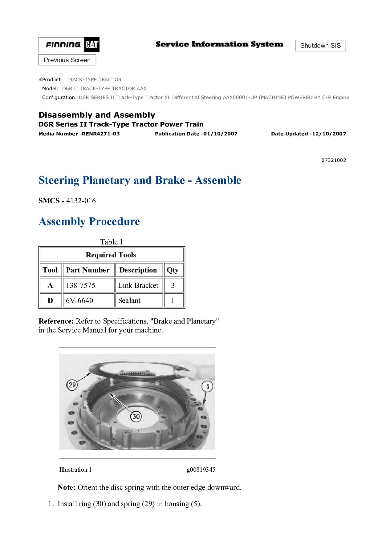
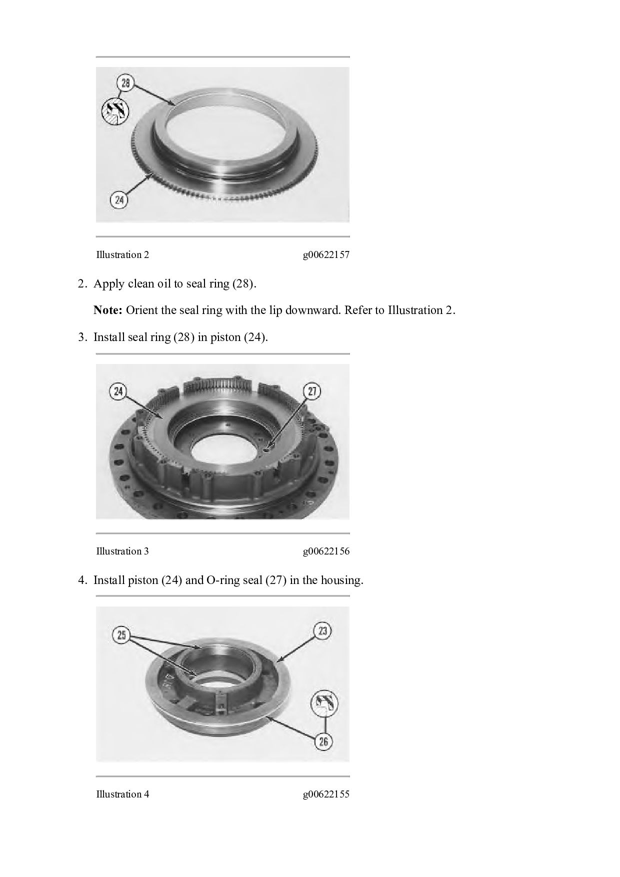
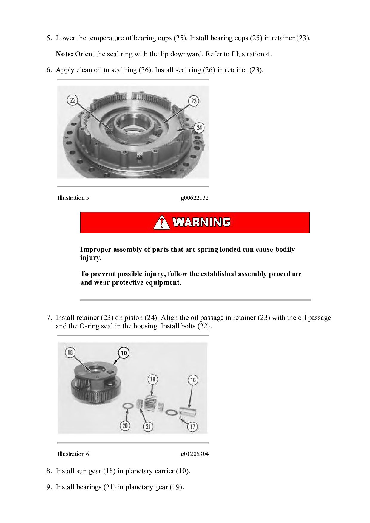
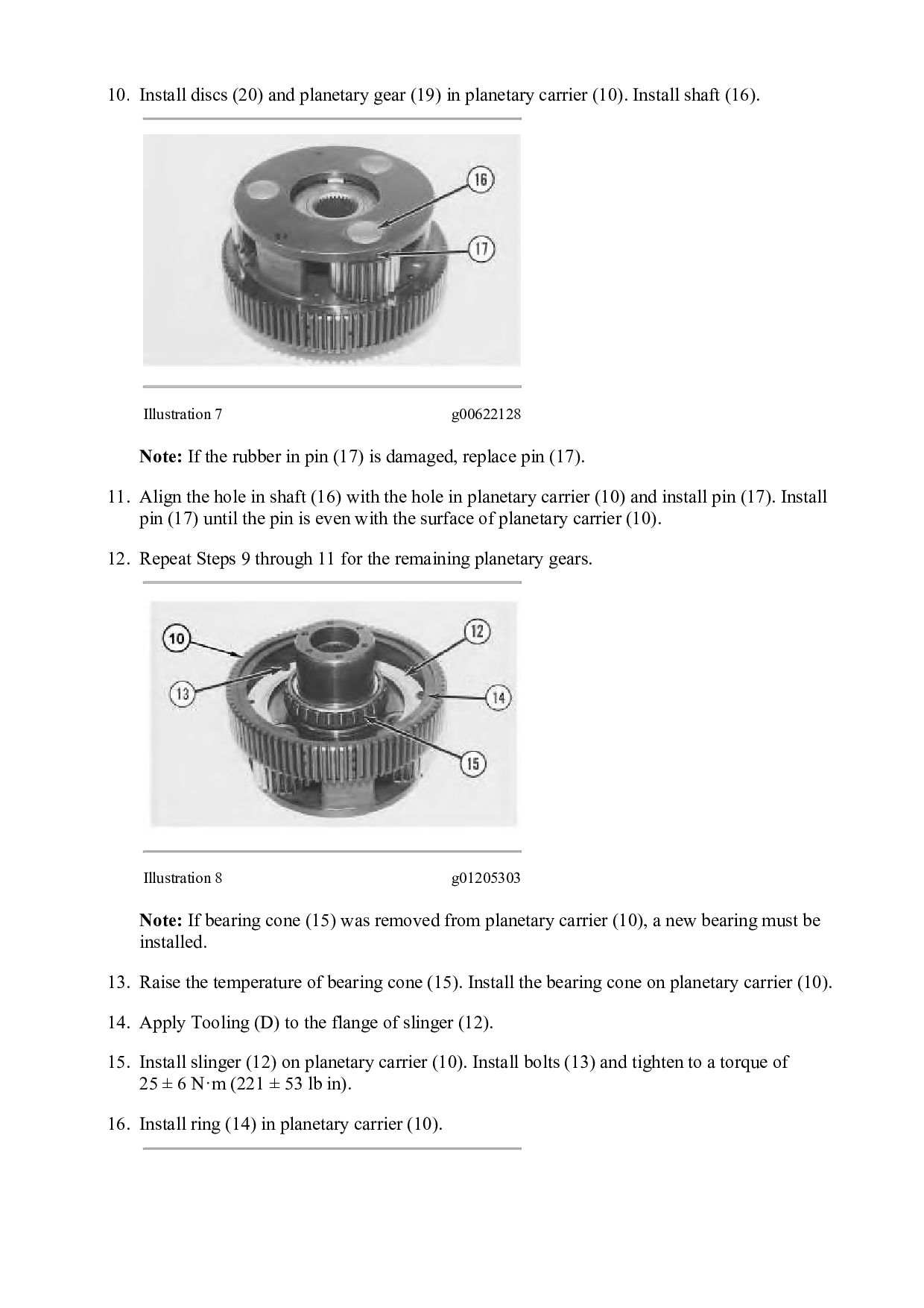
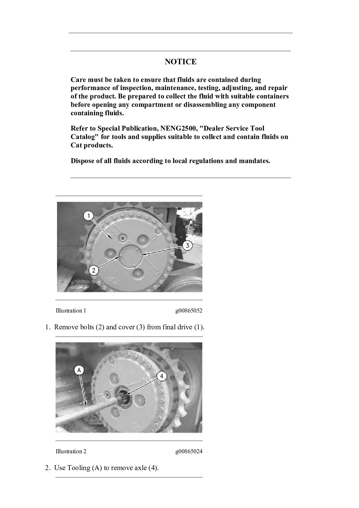
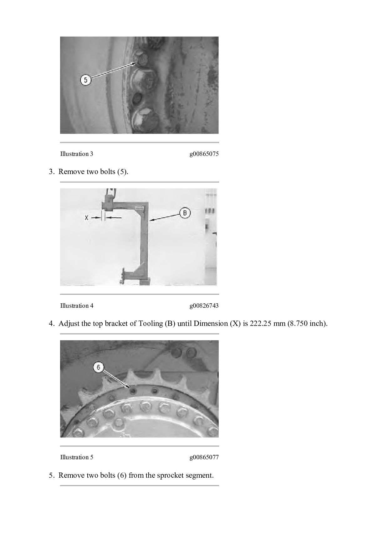
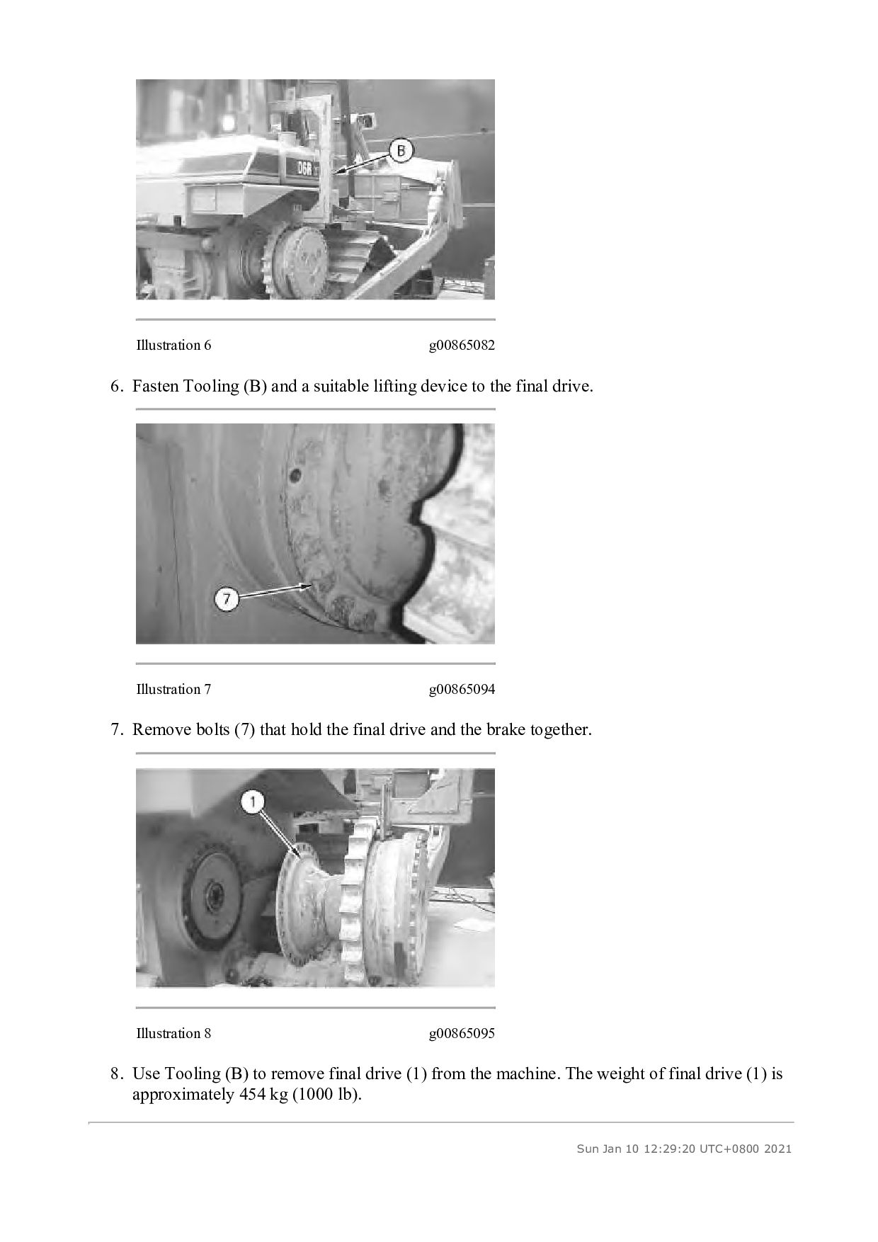
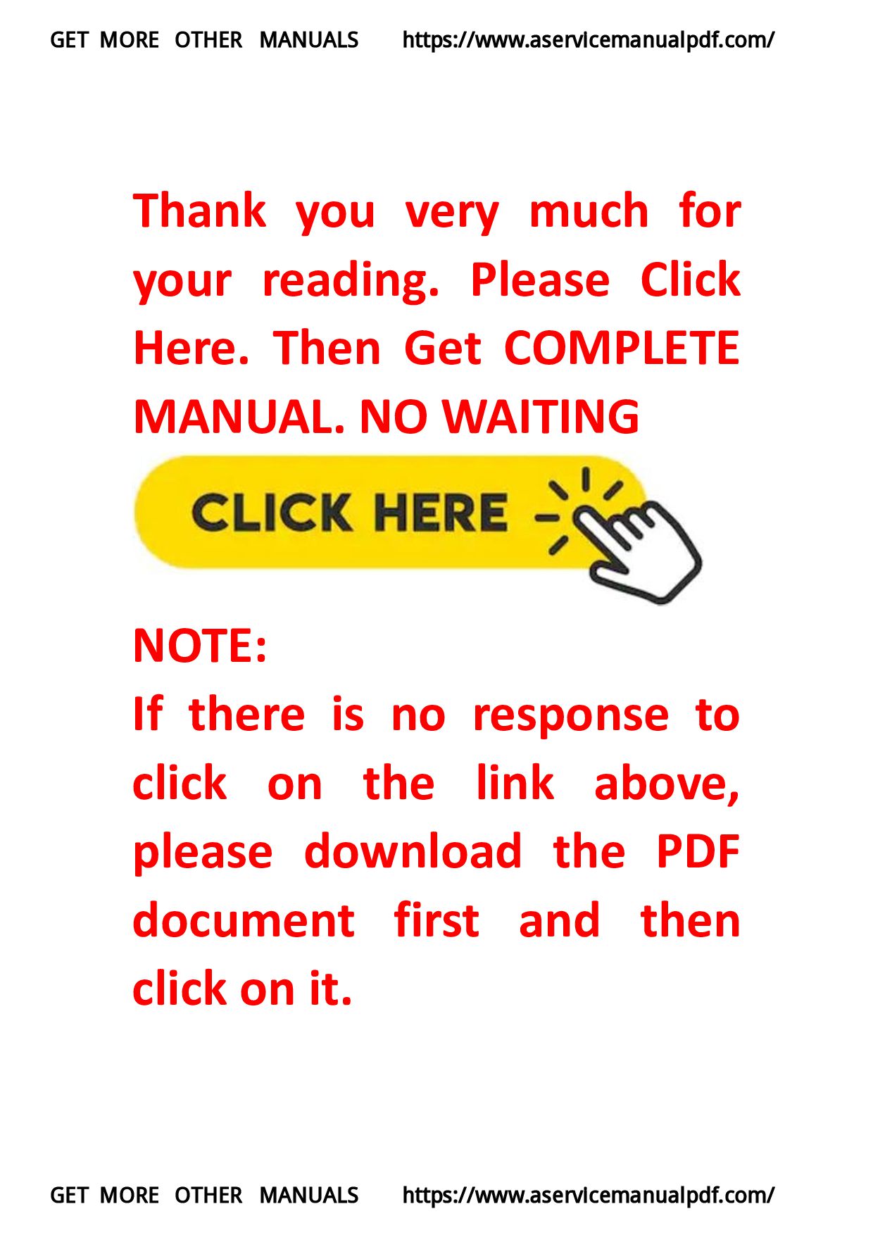
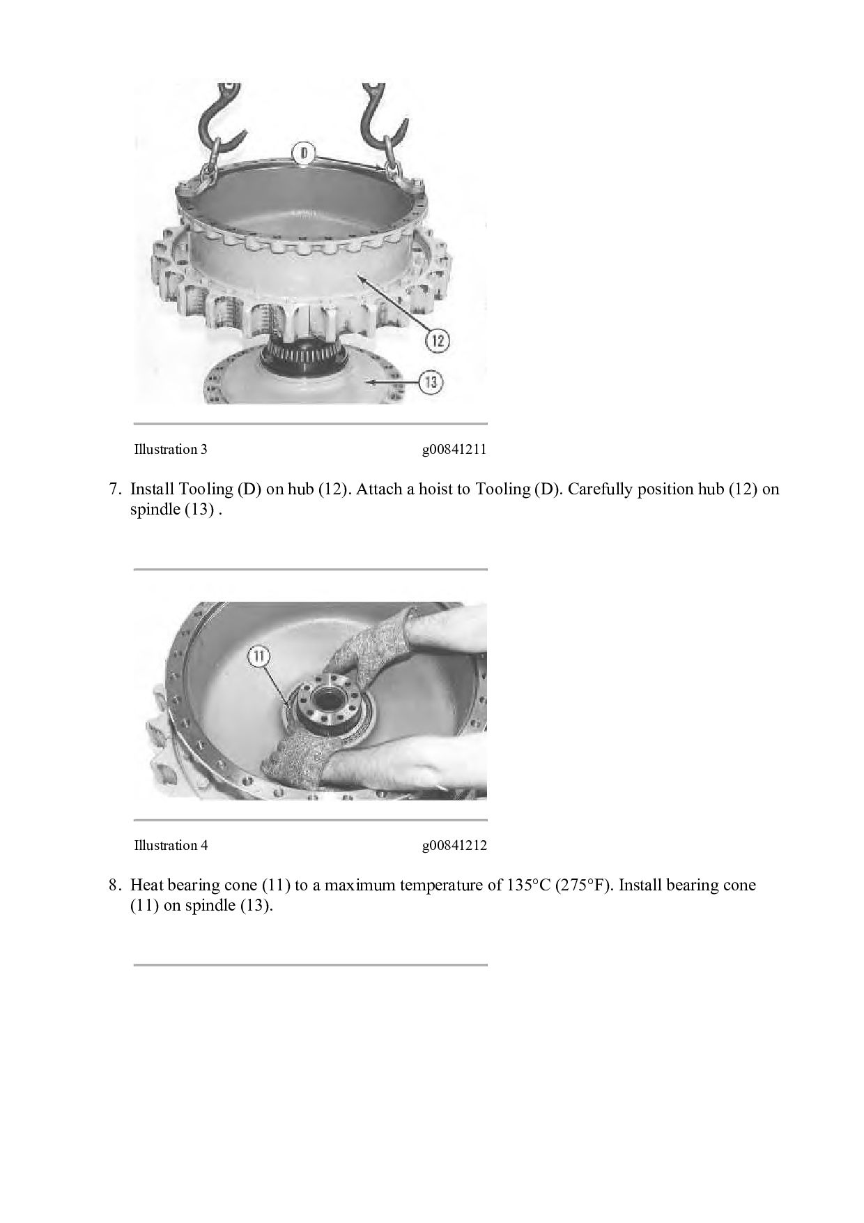
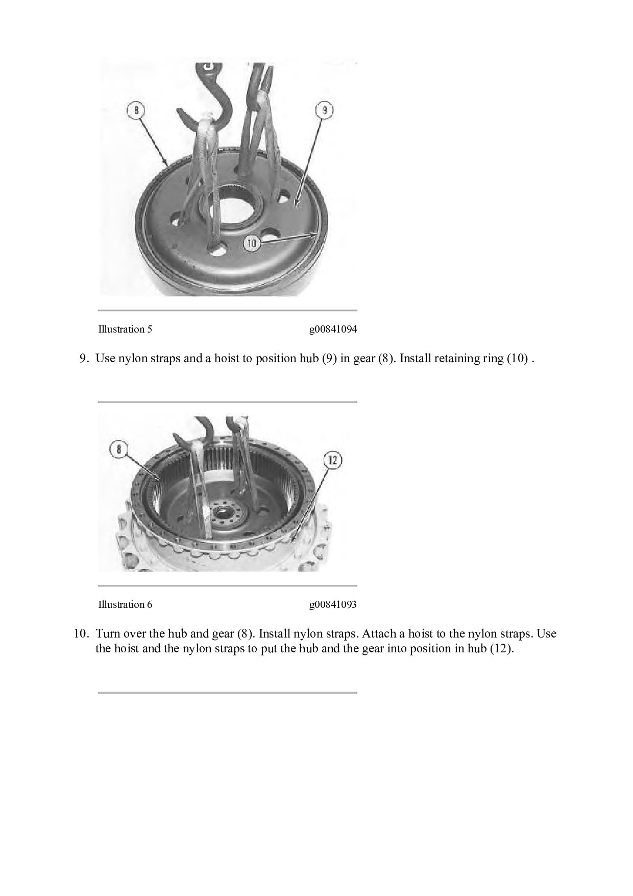
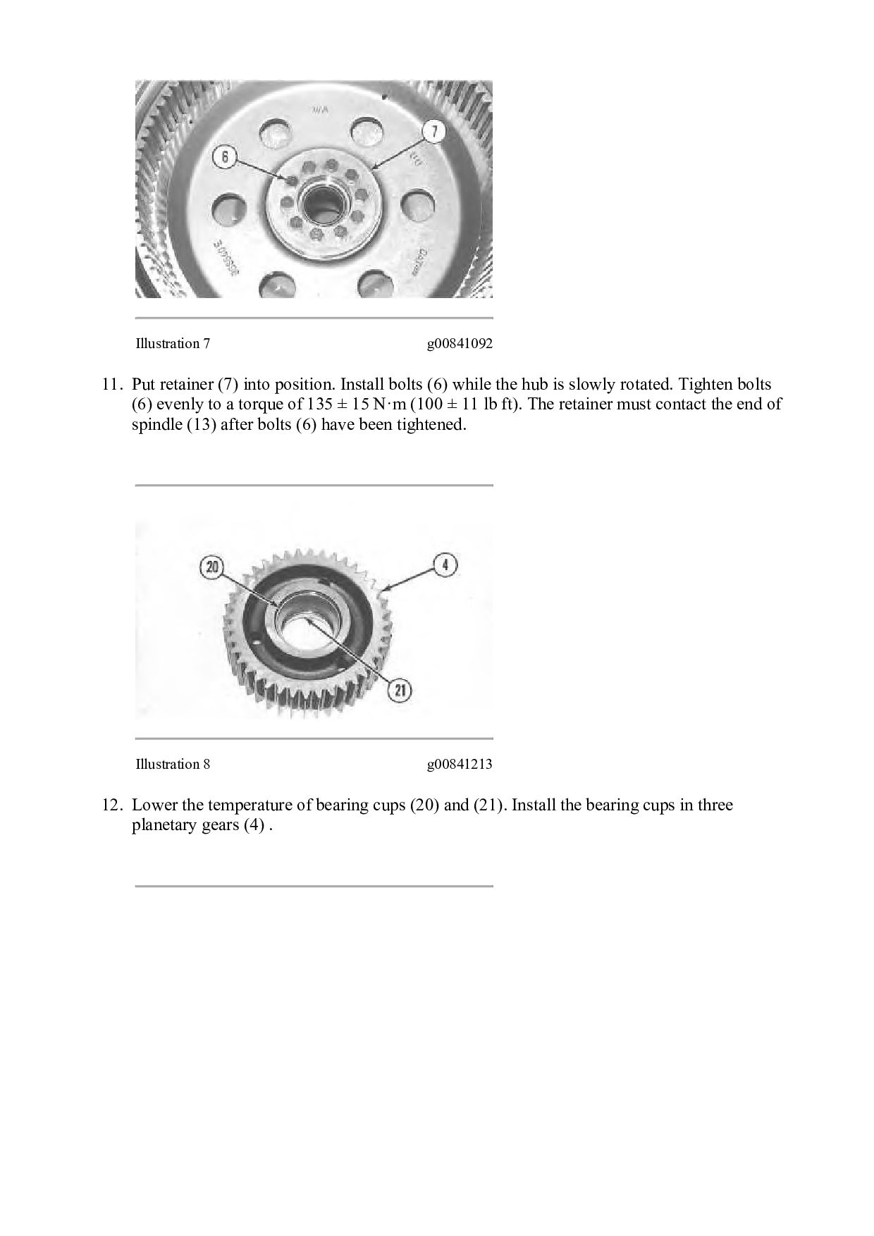
    contained during performance of inspection, maintenance, testing, adjusting, and repair of the product. Be prepared to collect the fluid with suitable containers before opening any compartment or disassembling any component containing fluids. Refer to Special Publication, NENG2500, "Dealer Service Tool Catalog" for tools and supplies suitable to collect and contain fluids on Cat products. Dispose of all fluids according to local regulations and mandates. Illustration 1 g00865052 1. Remove bolts (2) and cover (3) from final drive (1). Illustration 2 g00865024 2. Use Tooling (A) to remove axle (4).
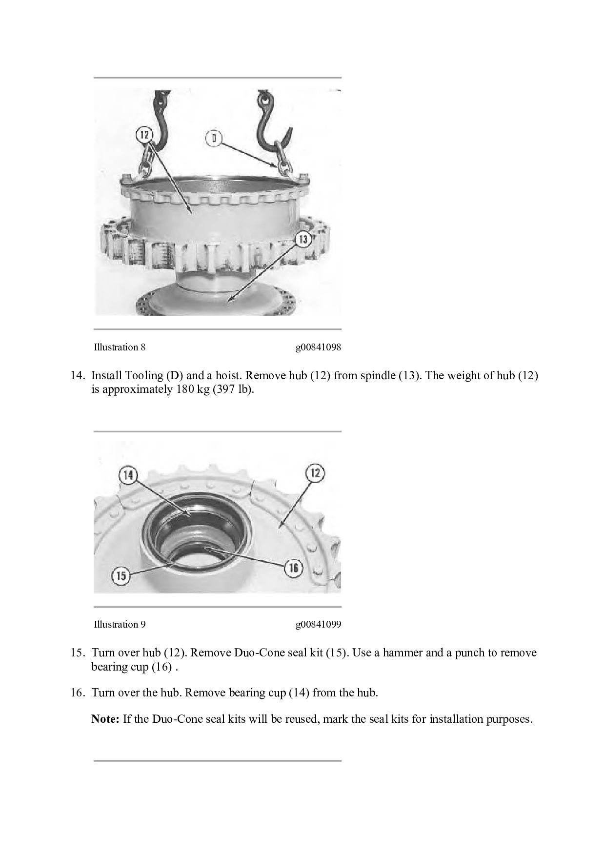
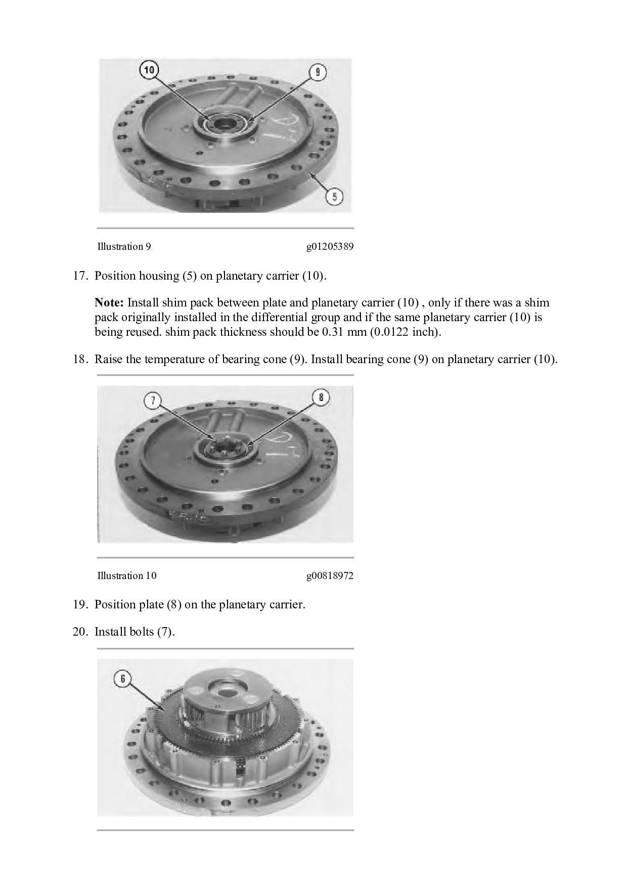
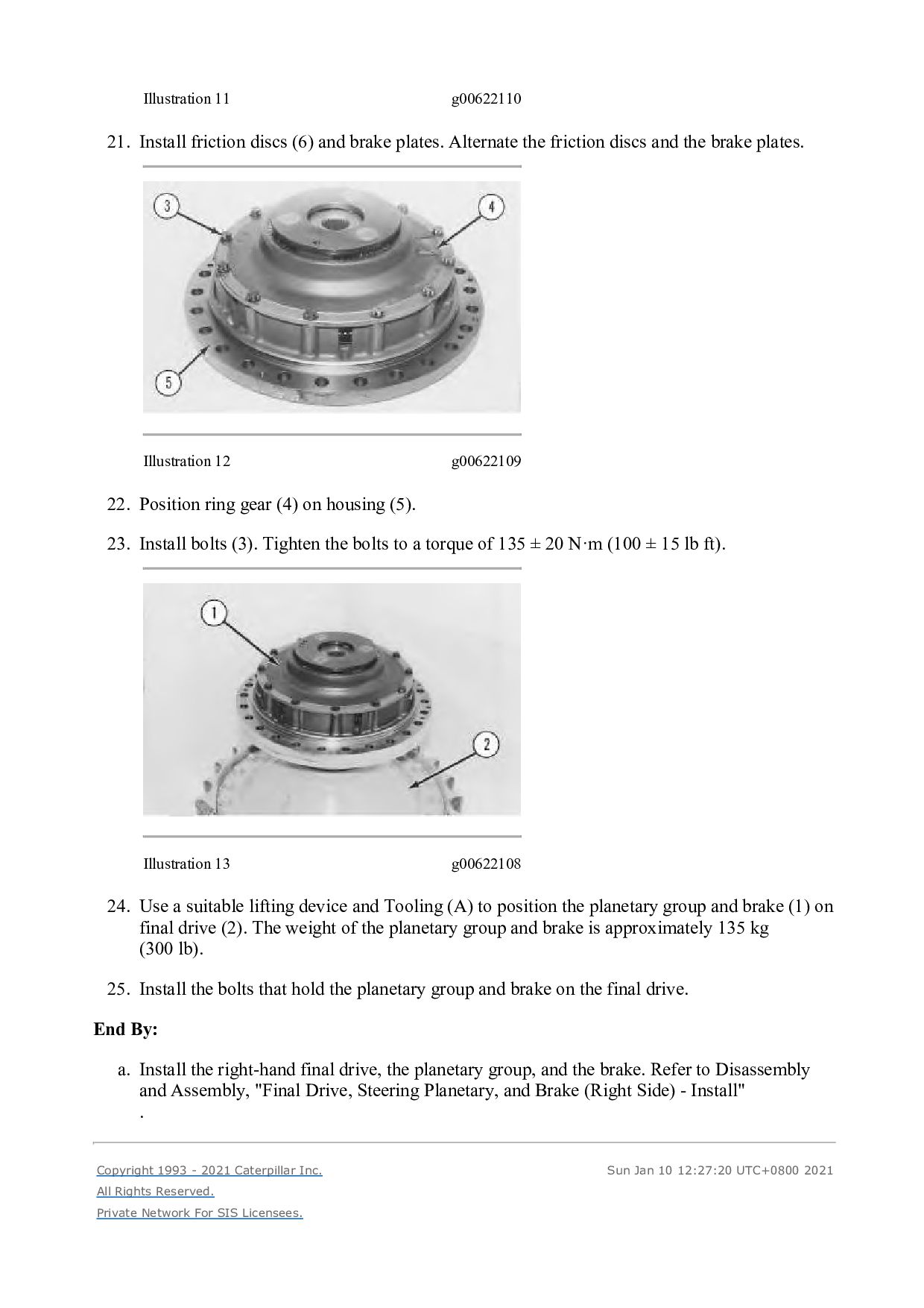
  19. Illustration 3 g00865075 3. Remove two bolts (5). Illustration 4

    g00826743 4. Adjust the top bracket of Tooling (B) until Dimension (X) is 222.25 mm (8.750 inch). Illustration 5 g00865077 5. Remove two bolts (6) from the sprocket segment.
  20. Illustration 6 g00865082 6. Fasten Tooling (B) and a suitable

    lifting device to the final drive. Illustration 7 g00865094 7. Remove bolts (7) that hold the final drive and the brake together. Illustration 8 g00865095 8. Use Tooling (B) to remove final drive (1) from the machine. The weight of final drive (1) is approximately 454 kg (1000 lb). Sun Jan 10 12:29:20 UTC+0800 2021
  21. Shutdown SIS Previous Screen Product: TRACK-TYPE TRACTOR Model: D6R II

    TRACK-TYPE TRACTOR AAX Configuration: D6R SERIES II Track-Type Tractor XL Differential Steering AAX00001-UP (MACHINE) POWERED BY C-9 Engine Disassembly and Assembly D6R Series II Track-Type Tractor Power Train Media Number -RENR4271-03 Publication Date -01/10/2007 Date Updated -12/10/2007 i01618664 Final Drive - Disassemble SMCS - 4050-015 Disassembly Procedure Table 1 Required Tools Tool Part Number Part Description Qty A 138-7573 Link Bracket 3 A 1A-2029 Bolt 3 B 1P-510 Driver Group 1 C FT-1934 Beam 1 C 6V-3160 Cylinder 1 C 6V-9061 Pump Group 1 C 1D-4621 Bolt 4 D 138-7574 Link Bracket 2 D 2A-1538 Bolt 2 Start By: A. Remove the final drives. Refer to Disassembly and Assembly, "Final Drive - Remove" for the correct procedure. Note: Cleanliness is an important factor. Before the disassembly procedure, the exterior of the component should be thoroughly cleaned. This will help to prevent dirt from entering the internal mechanism.
  22. Illustration 1 g00841087 1. Install Tooling (A) on the planetary

    carrier. Attach a hoist. 2. Remove bolts (1) that hold the planetary carrier to the hub. Remove planetary carrier (3) and the two O-ring seals from the hub. The weight of the planetary carrier is approximately 137 kg (302 lb). 3. Remove three retainers (2) . Illustration 2 g00841089 4. Place support under planetary carrier (3) in order to prevent damage. Use Tooling (B) and a press to remove the three planetary gear shafts. 5. Remove three planetary gears (4) from carrier (3) .
  23. Illustration 3 g00841091 6. Remove bearing cones (5) from each

    gear (4) . 7. Remove the bearing cups from each side of the gears. Illustration 4 g00841092 Illustration 5 g00841093 8. Remove bolts (6) and retainer (7) .
  24. 9. Use nylon straps and a hoist to remove the

    hub and ring gear (8). The weight of the hub and ring gear (8) is approximately 68 kg (150 lb). Illustration 6 g00841094 10. Turn over hub (9) and ring gear (8). Remove retaining ring (10). The weight of hub (9) is approximately 37 kg (82 lb). The weight of ring gear (8) is approximately 32 kg (71 lb). Use nylon straps and a hoist to remove hub (9) . Illustration 7 g00841095 11. Install Tooling (C) on hub (12). Note: Do not lift hub (12) too high. Do not allow hub (12) to contact the fitting on the hydraulic cylinder. 12. Use Tooling (C) to loosen hub (12) from spindle (13). Remove Tooling (C) . 13. Remove bearing cone (11) .
  25. Illustration 8 g00841098 14. Install Tooling (D) and a hoist.

    Remove hub (12) from spindle (13). The weight of hub (12) is approximately 180 kg (397 lb). Illustration 9 g00841099 15. Turn over hub (12). Remove Duo-Cone seal kit (15). Use a hammer and a punch to remove bearing cup (16) . 16. Turn over the hub. Remove bearing cup (14) from the hub. Note: If the Duo-Cone seal kits will be reused, mark the seal kits for installation purposes.
  26. Illustration 10 g00841101 Note: Bearing cone (18) may be damaged

    if the bearing cone is removed from spindle (13) . 17. Remove Duo-Cone seal kit (19) from spindle (13) . 18. If necessary, remove bearing cone (18) from the spindle. 19. Remove lip seal (17) from spindle (13) . Copyright 1993 - 2021 Caterpillar Inc. All Rights Reserved. Private Network For SIS Licensees. Sun Jan 10 12:30:20 UTC+0800 2021
  27. Shutdown SIS Previous Screen Product: TRACK-TYPE TRACTOR Model: D6R II

    TRACK-TYPE TRACTOR AAX Configuration: D6R SERIES II Track-Type Tractor XL Differential Steering AAX00001-UP (MACHINE) POWERED BY C-9 Engine Disassembly and Assembly D6R Series II Track-Type Tractor Power Train Media Number -RENR4271-03 Publication Date -01/10/2007 Date Updated -12/10/2007 i01618668 Final Drive - Assemble SMCS - 4050-016 Assembly Procedure Table 1 Required Tools Tool Part Number Part Description Qty A 138-7573 Link Bracket 3 A 1A-2029 Bolt 3 B 1P-510 Driver Group 1 D 138-7574 Link Bracket 2 D 2A-1538 Bolt 2 E 8M-9395 Installer 1 Note: Cleanliness is an important factor. Before assembly, all parts should be thoroughly cleaned in cleaning fluid. Allow the parts to air dry. Wiping cloths or rags should not be used to dry parts. Lint may be deposited on the parts which may cause later trouble. Inspect all parts. If any parts are worn or damaged, use new parts for replacement. 1. Apply clean oil to all the parts during assembly.
  28. Illustration 1 g00841209 2. Use Tooling (B) to install lip

    seal (17) in spindle (13). Put clean oil on the lip of the seal. 3. Heat bearing cone (18) to a maximum temperature of 135 °C (275 °F). Install bearing cone (18) on spindle (13) . Note: Before the installation of the Duo-Cone seal kit, refer to Disassembly and Assembly, "Duo-Cone Floating Seals - Install" for the correct procedure. 4. Use Tooling (E) to install the Duo-Cone seal kit on spindle (13) . Illustration 2 g00841210 5. Lower the temperature of bearing cups (14) and (16). Install bearing cups (14) and (16) in hub (12) . 6. Use Tooling (E) to install the Duo-Cone seal in hub (12) .
  29. Thank you very much for your reading. Please Click Here.

    Then Get COMPLETE MANUAL. NO WAITING NOTE: If there is no response to click on the link above, please download the PDF document first and then click on it.
  30. Illustration 3 g00841211 7. Install Tooling (D) on hub (12).

    Attach a hoist to Tooling (D). Carefully position hub (12) on spindle (13) . Illustration 4 g00841212 8. Heat bearing cone (11) to a maximum temperature of 135°C (275°F). Install bearing cone (11) on spindle (13).
  31. Illustration 5 g00841094 9. Use nylon straps and a hoist

    to position hub (9) in gear (8). Install retaining ring (10) . Illustration 6 g00841093 10. Turn over the hub and gear (8). Install nylon straps. Attach a hoist to the nylon straps. Use the hoist and the nylon straps to put the hub and the gear into position in hub (12).
  32. Illustration 7 g00841092 11. Put retainer (7) into position. Install

    bolts (6) while the hub is slowly rotated. Tighten bolts (6) evenly to a torque of 135 ± 15 N·m (100 ± 11 lb ft). The retainer must contact the end of spindle (13) after bolts (6) have been tightened. Illustration 8 g00841213 12. Lower the temperature of bearing cups (20) and (21). Install the bearing cups in three planetary gears (4) .
  33. https://www.aservicemanualpdf.com/ My Dear Friend! Thank you very much for visiting.

    Full manual if required, please enter the following URL into your browser. https://www.aservicemanualpdf.com/