Upgrade to Pro — share decks privately, control downloads, hide ads and more …

Caterpillar_Cat_977L_TRACK_TYPE_LOADER__Prefix_95X__Service_Repair_Manual__95X00001_and_up_.pdf

dcfv
May 20, 2024
6

 Caterpillar_Cat_977L_TRACK_TYPE_LOADER__Prefix_95X__Service_Repair_Manual__95X00001_and_up_.pdf

dcfv

May 20, 2024
Tweet

More Decks by dcfv

Transcript

  1. Shutdown SIS Previous Screen Product: TRACK LOADER Model: 977L TRACK

    LOADER 95X Configuration: 977L TRACK TYPE LOADER 95X00001-UP (MACHINE) POWERED BY 3306 ENGINE Disassembly and Assembly 977L TRACK-TYPE TRACTOR POWER TRAIN Media Number -SENR7794-00 Publication Date -01/09/1978 Date Updated -12/10/2001 Adjustment For Final Drive Bearings SMCS - 4164-11; 4164-12 Adjustment For Final Drive Bearings 1. Use tooling (A) to lift one side of the machine until the track is off the ground.
  2. 2. Install tooling (B) and lower the weight of the

    machine on tooling (B). 3. Remove guards (1) and (2) from the track roller frame. 4. Remove cap (3) and the gasket from the bearing. 5. Remove bolt (4), the nut, lockwasher and lock (5) from the holder assembly. 6. Remove lock (7) and check the torque on nut (8). The nut must be tightened to a torque of 600 to 700 lb.ft. (810 to 950 N·m). Install lock (7). 7. Use tool (C) to loosen adjustment nut (6). Turn the nut in a clockwise direction to loosen it.
  3. 8. Start the machine and turn the sprocket slowly while

    adjustment nut (6) is tightened with tooling (D) to a torque of 2500 ± 300 lb.ft. (3380 ± 410 N·m). Tighten nut (6) in a counterclockwise direction. On the left side of the machine the nut is tightened in a counterclockwise direction also. 9. Turn adjustment nut (6) clockwise with tooling (D) (about six to ten lugs) to lower the torque to less than 350 lb.ft. (470 N·m). NOTE: If it is not possible to get a torque below 350 lb.ft. after the adjustment nut is loosened, a separation of the tracks must be made to make the adjustment of the bearings. 10. Use tooling (D) to tighten adjustment nut (6) again to a torque of 350 ± 10 lb.ft. (470 ± 14 N·m). 11. Make a mark on nut (6) and the holder assembly. Tighten nut (6) in a counterclockwise direction 6.36 ± .06 in. (161.5 ± 1.52 mm) of the circumference as measured on the holder assembly outside diameter. 12. If necessary, tighten nut (6) more to install lock (5) in one of the notches of adjustment nut (6). Install the bolt, nut and lockwasher to hold the lock in position. 13. Install the gasket and cap (3).
  4. 14. Install guards (1) and (2) on the track roller

    frame. 15. Lift the machine with tooling (A) and remove tooling (B). Lower the machine to the ground and remove tooling (A). Copyright 1993 - 2021 Caterpillar Inc. All Rights Reserved. Private Network For SIS Licensees. Mon Jun 14 09:47:56 UTC+0800 2021
  5. Shutdown SIS Previous Screen Product: TRACK LOADER Model: 977L TRACK

    LOADER 95X Configuration: 977L TRACK TYPE LOADER 95X00001-UP (MACHINE) POWERED BY 3306 ENGINE Disassembly and Assembly 977L TRACK-TYPE TRACTOR POWER TRAIN Media Number -SENR7794-00 Publication Date -01/09/1978 Date Updated -12/10/2001 Final Drive Cases, Gears, Idler Pinions And Bearings SMCS - 4059; 4075-11; 4075-12 Remove Final Drive Cases, Gears, Idler Pinions And Bearings start by: a) remove sprocket assemblies
  6. https://www.aservicemanualpdf.com/ My Dear Friend! Thank you very much for visiting.

    Full manual if required, please enter the following URL into your browser. https://www.aservicemanualpdf.com/
  7. 1. Remove the bolts that hold final drive case (1)

    in position. 2. Install three 1/2"-13 NC guide pins (3) through the final drive case and into the steering clutch case. Install two 1/2"-13 NC forcing screws (2) in the final drive case. Tighten the screws evenly until the case is approximately .25 in. (6.35 mm) away from the steering clutch case. 3. Install a piece of wire around two of the guide pins to hold the idler pinion in place. NOTICE The wire is to keep the planet carrier in position so it will not fall from the steering clutch case when the final drive case is removed. 4. Tighten the forcing screws until tool (A) and a hoist can be fastened to final drive case (1). Remove case (1) from the guide pins. The weight of the final drive case is 250 lb. (113 kg). 5. Remove the plugs from case (1) with tool group (B).
  8. 6. Remove the dowels from case (1) with a 1/4"-20

    NC bolt. 7. Use tooling (C) to remove race and roller assemblies (4) and (5) from the final drive case. 8. Fasten a hoist to the gear and hub (6). Remove the gear and hub from the sprocket shaft. The weight of the gear and hub is 265 lb. (119 kg). 9. Put the gear and hub on wood blocks. Remove the bearing cone from the hub with tooling (D). 10. Remove the nuts from bolts (8). Use a hammer and soft punch to remove bolts (8) from gear (7) and hub (6) as shown.
  9. 11. Use a nylon strap and a pin or bolt

    with a length that is longer than the inside diameter of hub (6) to fasten a hoist to the hub. Remove hub (6) from gear (7). The weight of the hub is 145 lb. (65 kg). 12. If necessary, remove bearing cup (9) from the steering clutch case. 13. Remove the wire from the gear and pinion. Fasten a hoist and remove gear (10) and the pinion from the steering clutch case. The weight of the gear and pinion is 75 lb. (34 kg). 14. Put the gear and pinion on wood blocks. Use tooling (E) to remove the bearing races (11) from each end of the pinion shaft. 15. Remove the pinion shaft from the gear as follows: a) Put the gear and pinion shaft in a press as shown.
  10. TYPICAL EXAMPLE b) Put a small amount of pressure on

    the pinion shaft with the press. Push the ring in the groove on the pinion shaft with a hammer and punch. The ring will stay in the groove because of the pressure on the pinion shaft. c) When the ring is completely in the groove, the pinion shaft will slide out of the gear. NOTICE Too much pressure on the pinion shaft can cause damage to the gear. 16. If necessary, remove bearing race (12) with tooling (E). 17. Use three 1/2"-13 NC forcing screws to remove cage (13) from the steering clutch case.
  11. 18. Use a 1/4"-20 NC bolt to remove the dowel

    from cage (13). Remove O-ring seal (14) from the cage. 19. Use tooling (C) to remove the race and roller assembly from the cage. Install Final Drive Cases, Gears, Idler Pinions And Bearings 1. Lower the temperature of roller and race assembly (1) and install it in cage (2). Make sure the hole in the race and roller assembly is in alignment with the hole in cage (2) at assembly. 2. Put clean oil on O-ring seal (4) and install it on cage (2).
  12. 3. Install dowel (3) to hold the race and roller

    assembly in cage (2). 4. Heat bearing race (5) to a maximum temperature of 275°F (135°C). Install bearing race (5) on the pinion as shown. 5. Lower the temperature of bearing cup (6) and install it in the steering clutch case as shown. 6. Install the bearing and cage (2) in the steering clutch case. Make sure the oil groove next to the bearing in the cage is at the bottom before the bolts are tightened. 7. If a separation of the idler gear and pinion was made, install a new retainer in the pinion. Install the gear over the pinion so the deep chamfer is used to put the retainer under compression. Make sure the retainer is engaged in the groove of the gear. 8. Heat bearing races (7) and (8) to a maximum temperature of 275°F (135°C) and install them on the idler pinion. 9. Put 1P808 General Purpose Lubricant in the bearing to hold the rollers out for installation of gear (9) and the pinion. Fasten a hoist to the gear and pinion. Install the gear (9) and pinion in the steering clutch case. 10. Install three 1/2"-13 NC guide pins in the steering clutch case for installation of the final drive case. Fasten a wire around the guide bolts, idler gear (9) and the pinion.
  13. NOTE: The wire will hold idler gear (9) and the

    pinion in position until the final drive case is installed. 11. Fasten a hoist to hub (10) and put it in position in gear (11). Install the bolts, washers and nuts that hold the hub and gear together. 12. Heat bearing cone (12) to a maximum temperature of 275° F (135° C). Install the bearing cone on the hub as shown. 13. Fasten a hoist to hub (10) and the gear. Put hub (10) and the gear in position on the sprocket shaft. 14. Lower the temperature of race and roller assemblies (14) and (15). Install the race and roller assemblies in case (13). Make sure the hole in the race and roller assemblies are in alignment with the dowel holes in case (13).
  14. 15. Install dowel (16) and the plug in case (13)

    to hold race and roller assembly (15). Install the dowel and plug to hold race and roller assembly (14). Put 1P808 General Purpose Lubricant in the race and roller assemblies to hold the rollers out to prevent damage of parts when case (13) is installed. 16. Fasten a hoist to case (13) with tool (A). Put 7M7260 Liquid Gasket Material on the machined surface of the steering clutch case and case (13). 17. Put case (13) on the guide pins. Removo tool (A) and the wire used to hold the idler pinion. Install the bolts and washers that hold case (13). Tighten the bolts to a torque of 100 ± 10 lb.ft. (135 ± 14 N·m). 18. Fill the steering clutch case and final drive cases with oil to the correct level. See LUBRICATION AND MAINTENANCE GUIDE. end by: a) install sprocket assemblies Copyright 1993 - 2021 Caterpillar Inc. All Rights Reserved. Private Network For SIS Licensees. Mon Jun 14 09:48:53 UTC+0800 2021
  15. Shutdown SIS Previous Screen Product: TRACK LOADER Model: 977L TRACK

    LOADER 95X Configuration: 977L TRACK TYPE LOADER 95X00001-UP (MACHINE) POWERED BY 3306 ENGINE Disassembly and Assembly 977L TRACK-TYPE TRACTOR POWER TRAIN Media Number -SENR7794-00 Publication Date -01/09/1978 Date Updated -12/10/2001 Sprocket Shafts SMCS - 4058-11; 4058-12 Remove Sprocket Shafts start by: a) remove final drive cases, gears, idler pinions and bearings
  16. VIEW FROM UNDER MACHINE 1. Remove ring (2) and the

    pin from spanner nut (1). 2. Loosen nut (1) with tool (A) until there is a clearance of .125 in. (3.2 mm) between the nut and the steering clutch case. Do not remove nut (1) from the sprocket shaft threads until the shaft is loosened with tooling (B). The nut will hold the shaft when it is loosened from the taper in the steering clutch case. 3. Install tooling (B) to remove the sprocket shaft as follows: a) Install the 5P4183 Adapter on the end of the sprocket shaft. Put the 5P4181 Adapter in the 5P4183 Adapter and install a 7M9772 Pin to hold the adapters together. Install a wire or 3P1770 Pin on each side of the pin to hold it in position. b) Install the 7M9773 Adapter on the 5P4181 Adapter. c) Connect the 9H3992 Head to the cylinder group with the 6H4158 Pins. Put a 7B2499 Ring on each side of the pins to hold them. d) Install the 7M9774 Coupling on the end of the cylinder group. e) Fasten a hoist to the cylinder group and put it in position on the sleeve. f) Install a 7M9772 Pin through the 7M9774 Coupling and 5P4181 Adapter. Put a wire or 3P1770 Pin on each side of the 7M9772 Pin to hold it. 4. Fasten a hoist to tooling (B) and loosen the sprocket shaft. Remove tooling (B). Remove nut (1) from the sprocket shaft threads.
  17. 5. Fasten a hoist to sprocket shaft (3) and remove

    it from the steering clutch case. The weight of the sprocket shaft is 100 lb. (45 kg). Install Sprocket Shafts 1. Fasten a hoist to sprocket shaft (1) and put it in the steering clutch case as far as possible by hand. 2. Put the spanner nut on the end of the sprocket shaft under the steering clutch case.
  18. 3. Install tooling (A) on the end of the sprocket

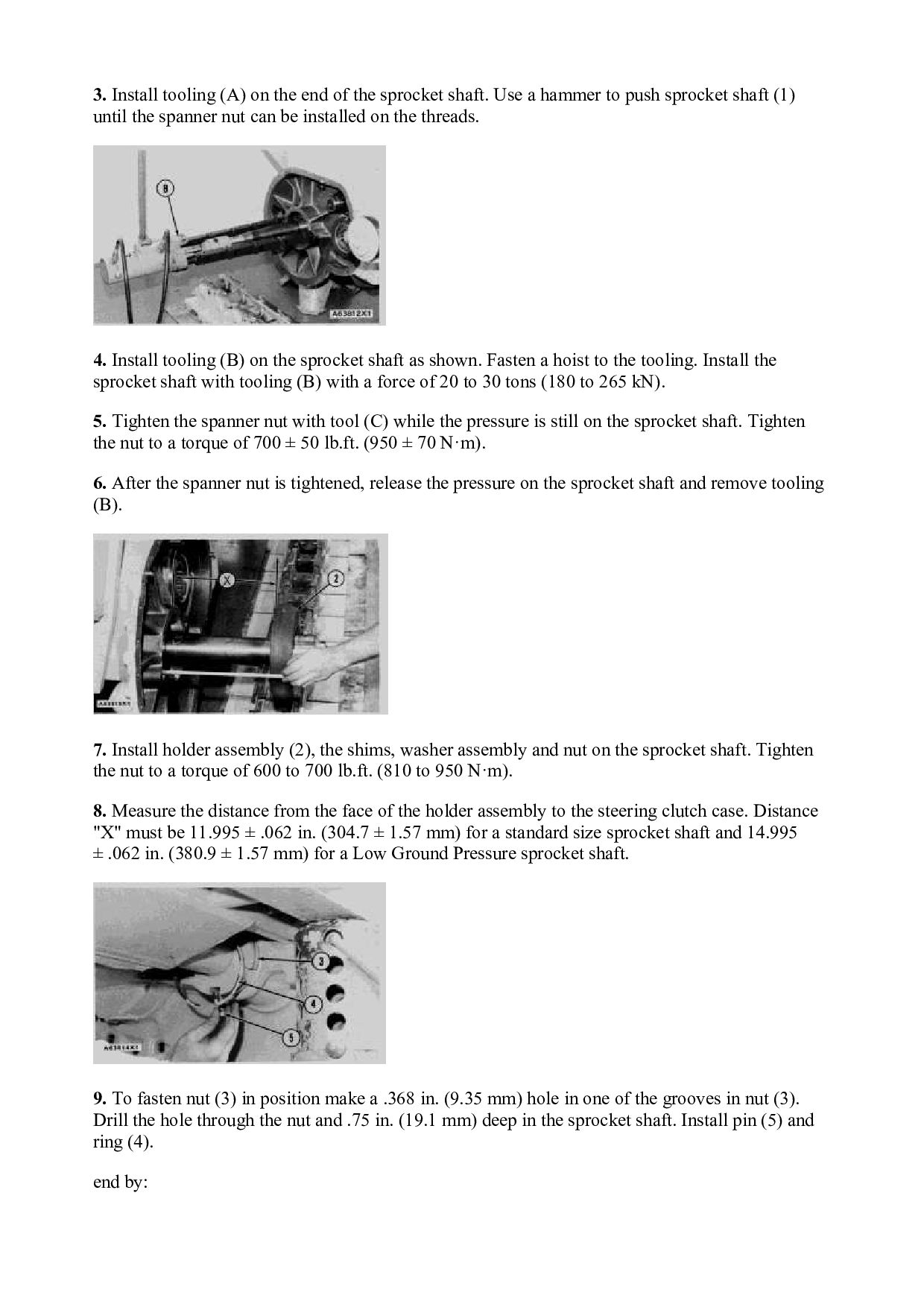
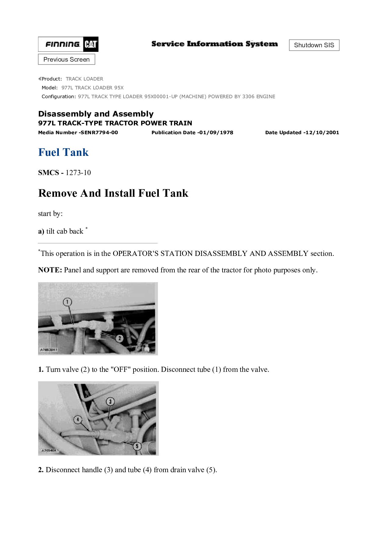
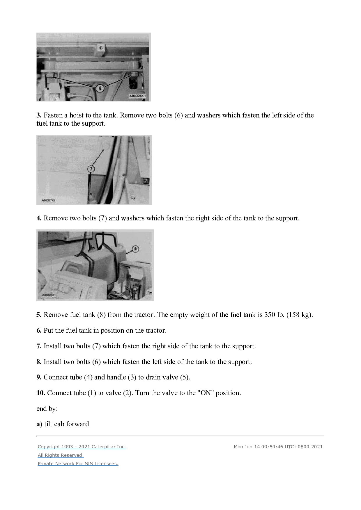
    shaft. Use a hammer to push sprocket shaft (1) until the spanner nut can be installed on the threads. 4. Install tooling (B) on the sprocket shaft as shown. Fasten a hoist to the tooling. Install the sprocket shaft with tooling (B) with a force of 20 to 30 tons (180 to 265 kN). 5. Tighten the spanner nut with tool (C) while the pressure is still on the sprocket shaft. Tighten the nut to a torque of 700 ± 50 lb.ft. (950 ± 70 N·m). 6. After the spanner nut is tightened, release the pressure on the sprocket shaft and remove tooling (B). 7. Install holder assembly (2), the shims, washer assembly and nut on the sprocket shaft. Tighten the nut to a torque of 600 to 700 lb.ft. (810 to 950 N·m). 8. Measure the distance from the face of the holder assembly to the steering clutch case. Distance "X" must be 11.995 ± .062 in. (304.7 ± 1.57 mm) for a standard size sprocket shaft and 14.995 ± .062 in. (380.9 ± 1.57 mm) for a Low Ground Pressure sprocket shaft. 9. To fasten nut (3) in position make a .368 in. (9.35 mm) hole in one of the grooves in nut (3). Drill the hole through the nut and .75 in. (19.1 mm) deep in the sprocket shaft. Install pin (5) and ring (4). end by:
  19. a) install final drive cases, gears, idler pinions and bearings

    Copyright 1993 - 2021 Caterpillar Inc. All Rights Reserved. Private Network For SIS Licensees. Mon Jun 14 09:49:50 UTC+0800 2021
  20. Shutdown SIS Previous Screen Product: TRACK LOADER Model: 977L TRACK

    LOADER 95X Configuration: 977L TRACK TYPE LOADER 95X00001-UP (MACHINE) POWERED BY 3306 ENGINE Disassembly and Assembly 977L TRACK-TYPE TRACTOR POWER TRAIN Media Number -SENR7794-00 Publication Date -01/09/1978 Date Updated -12/10/2001 Fuel Tank SMCS - 1273-10 Remove And Install Fuel Tank start by: a) tilt cab back * *This operation is in the OPERATOR'S STATION DISASSEMBLY AND ASSEMBLY section. NOTE: Panel and support are removed from the rear of the tractor for photo purposes only. 1. Turn valve (2) to the "OFF" position. Disconnect tube (1) from the valve. 2. Disconnect handle (3) and tube (4) from drain valve (5).
  21. 3. Fasten a hoist to the tank. Remove two bolts

    (6) and washers which fasten the left side of the fuel tank to the support. 4. Remove two bolts (7) and washers which fasten the right side of the tank to the support. 5. Remove fuel tank (8) from the tractor. The empty weight of the fuel tank is 350 lb. (158 kg). 6. Put the fuel tank in position on the tractor. 7. Install two bolts (7) which fasten the right side of the tank to the support. 8. Install two bolts (6) which fasten the left side of the tank to the support. 9. Connect tube (4) and handle (3) to drain valve (5). 10. Connect tube (1) to valve (2). Turn the valve to the "ON" position. end by: a) tilt cab forward Copyright 1993 - 2021 Caterpillar Inc. All Rights Reserved. Private Network For SIS Licensees. Mon Jun 14 09:50:46 UTC+0800 2021
  22. Shutdown SIS Previous Screen Product: TRACK LOADER Model: 977L TRACK

    LOADER 95X Configuration: 977L TRACK TYPE LOADER 95X00001-UP (MACHINE) POWERED BY 3306 ENGINE Disassembly and Assembly 977L TRACK-TYPE TRACTOR POWER TRAIN Media Number -SENR7794-00 Publication Date -01/09/1978 Date Updated -12/10/2001 Operator Platform Support SMCS - 1273-10 Remove Operator Platform Support start by: a) tilt cab back * b) remove batteries * c) remove hydraulic tank ** d) remove fuel tank *These operations are in the OPERATOR'S STATION DISASSEMBLY AND ASSEMBLY section. **This operation is in VEHICLE SYSTEMS DISASSEMBLY AND ASSEMBLY section. 1. Remove a pin and cotter pin and disconnect the transmission control lock lever linkage (1). Remove two bolts (4) and remove transmission shift linkage rods (3) and (6). Disconnect linkage rod (5) from lever (2).
  23. 2. Remove bolt (8) to remove wire harness (7) and

    battery cable (9). 3. Remove bolt (11) from panel on each side of the machine. Disconnect two hoses (10) from the bottom of the transmission hydraulic filter. 4. Remove clips (12) and wire (13) from the support. Remove four bolts (14) which fasten the right side of the support to the bevel gear case. 5. Remove clips (15) and (17). Remove wire (16) from the support. Remove four bolts (18) which fasten the left side of the support to the bevel gear case.
  24. 6. Put identification on two tubes (20) and disconnect from

    water separator (19). 7. Remove two springs (25). Disconnect two brake linkage rods (22) and (23) from levers (26). Remove cotter pin and pin and remove ratchet (21). Remove two cotter pins and a pin and remove yoke assembly (24). 8. Disconnect two tubes (29) and remove magnetic screen assembly (27). Remove bolt and clip (32) and remove battery cable (31) from the support assembly. Remove tool box (28), battery platform (33) and tool box tray (30) from the support assembly. 9. Remove spout assembly (33) and tube assembly (34) from the bevel gear case and support assembly.
  25. 10. Remove two bolts and remove bracket (35) from the

    right side of the support assembly. 11. Fasten a hoist to operator platform support (36) as shown. Carefully remove the support from the machine. The weight of the support assembly is 480 lb. (216 kg). Install Operator Platform Support 1. Fasten a hoist to the operator platform support assembly (1) as shown. Carefully lower the support on to the machine. Install the eight bolts and spacers which fasten the support assembly to the bevel gear case. Tighten the bolts to a torque of 225 ± 18 lb.ft. (305 ± 25 N·m). The weight of the support assembly is 480 lb. (216 kg). 2. Install bracket (2) on the support assembly with two bolts.
  26. 3. Use new gaskets and install tube assembly (3) and

    spout assembly (4) on the support assembly and bevel gear case. 4. Install tool box tray (8), battery platform (11) and tool box (6) on the support assembly. Put battery cable (10) in position and install clip (9) which fastens the cable to the support assembly. Inspect and make replacement, if necessary, of the O-ring seals on tubes (7). Install magnetic filter (5) and connect tubes (7). 5. Install parking brake yoke assembly (14) and ratchet (12). Connect brake linkage rods (13) and (15) to levers (17) and (19). Connect springs (16) and (18) to the bottom of battery platform and the parking brake linkage. 6. Connect two tubes (21) to water separator (20).
  27. Please write to us. Our email: [email protected] Please go to

    the homepage to get the full manual, or other brand PDF manuals. Home Site: aservicemanualpdf.com
  28. Thank you very much for your reading. Please Click Here.

    Then Get COMPLETE MANUAL. NO WAITING NOTE: If there is no response to click on the link above, please download the PDF document first and then click on it.
  29. 7. Put wire (24) in position on the left side

    of the support assembly and install clips (22) and (23) which fasten the wire to the support. 8. Put wire (25) in position on the right side of the support assembly. Install clips (26) which fasten the wire to the support. 9. Install bolt (29) in panel (28) on each side of the machine. Inspect and make replacements, if necessary, of the O-ring seals on hoses (27). Install the hoses on the transmission hydraulic filter. 10. Put wire harness (32) and battery cable (30) in position and install clip (31).
  30. 11. Install transmission control lock lever linkage (33). Connect shift

    linkage rod (37) to lever (34). Connect shift linkage rod (39) to lever (36). Connect linkage rod (38) to lever (35). end by: a) install fuel tank b) install hydraulic tank * c) install batteries ** d) tilt cab forward ** *This operation is in VEHICLE SYSTEMS DISASSEMBLY AND ASSEMBLY section. **These operations are in OPERATOR'S STATION DISASSEMBLY AND ASSEMBLY section. Copyright 1993 - 2021 Caterpillar Inc. All Rights Reserved. Private Network For SIS Licensees. Mon Jun 14 09:51:43 UTC+0800 2021
  31. Shutdown SIS Previous Screen Product: TRACK LOADER Model: 977L TRACK

    LOADER 95X Configuration: 977L TRACK TYPE LOADER 95X00001-UP (MACHINE) POWERED BY 3306 ENGINE Disassembly and Assembly 977L TRACK-TYPE TRACTOR POWER TRAIN Media Number -SENR7794-00 Publication Date -01/09/1978 Date Updated -12/10/2001 Steering Clutch Hydraulic Control Valve SMCS - 4102-15; 4102-16; 4102-11; 4102-12 Remove Steering Clutch Hydraulic Control Valve start by: a) tilt cab back * b) remove batteries * c) remove fuel tank *These operations are in OPERATOR'S STATION DISASSEMBLY AND ASSEMBLY section. 1. Remove two springs (1) from the parking brake linkage and battery platform. 2. Remove four bolts (4) and the two bolts which fasten tool box (2) to battery platform (3). Remove the battery platform.
  32. https://www.aservicemanualpdf.com/ My Dear Friend! Thank you very much for visiting.

    Full manual if required, please enter the following URL into your browser. https://www.aservicemanualpdf.com/