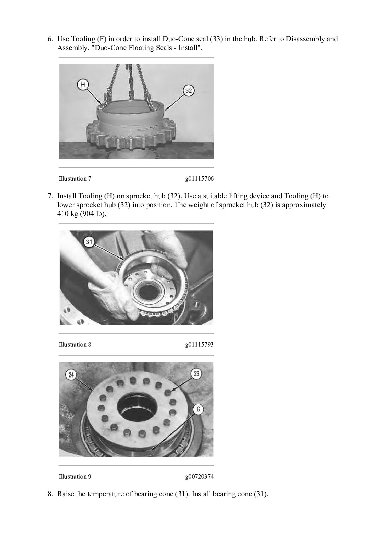
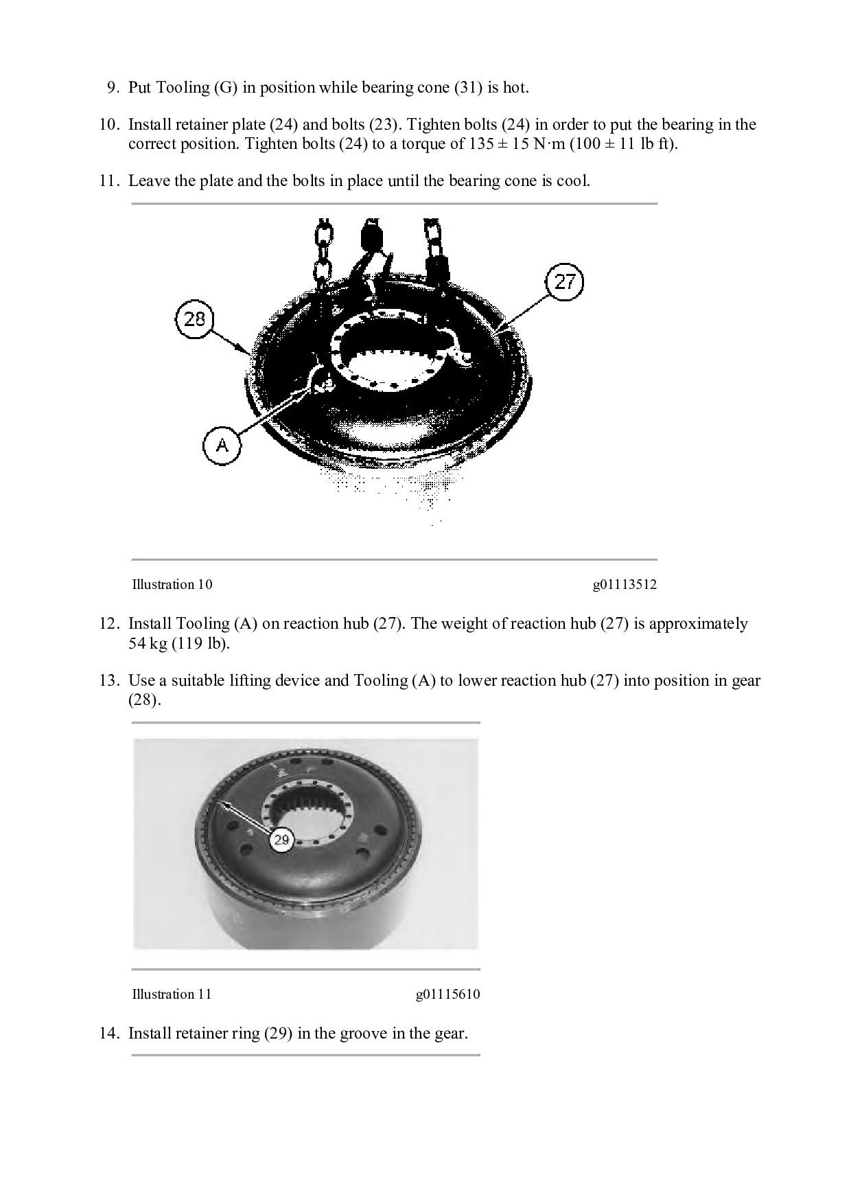
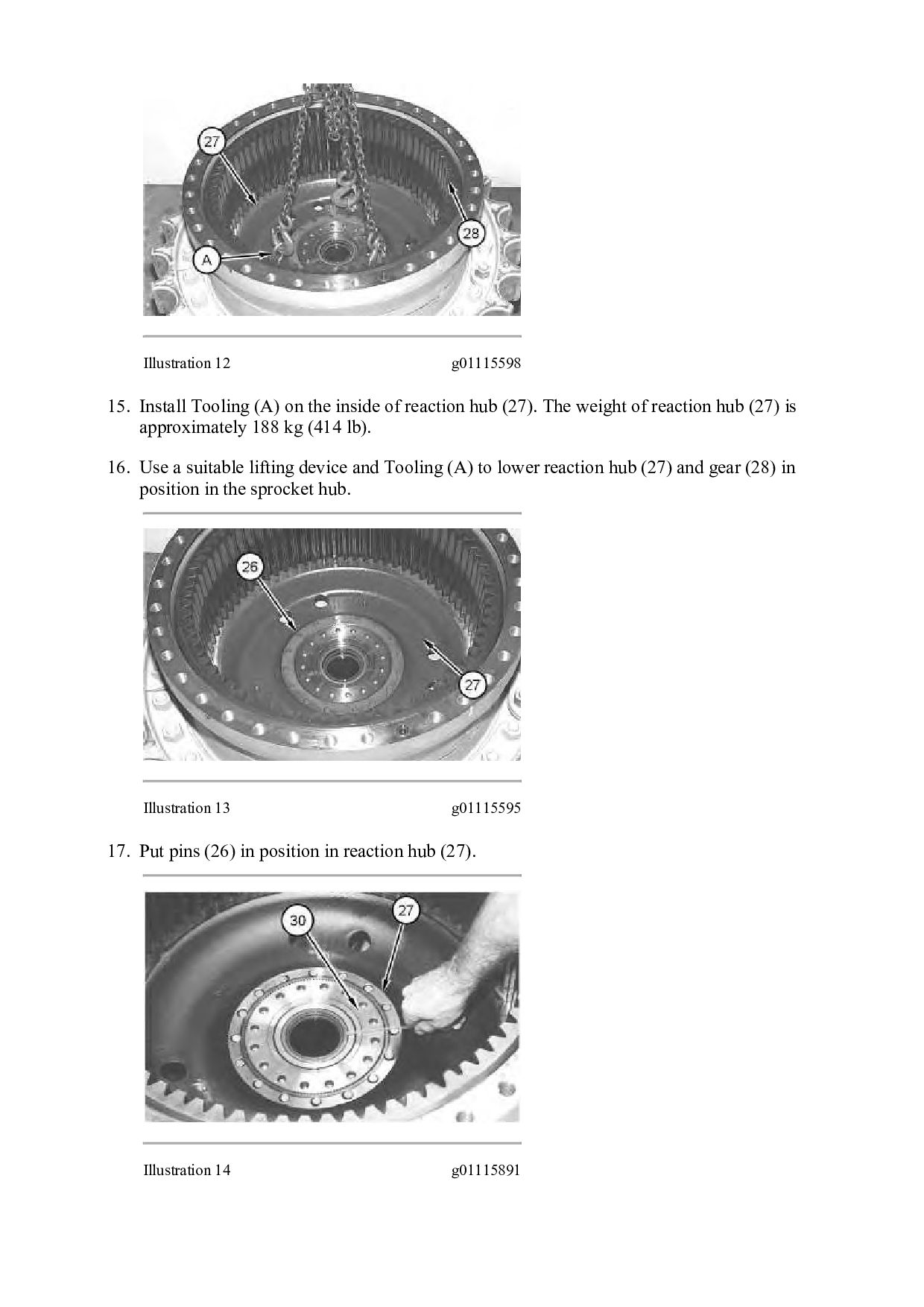
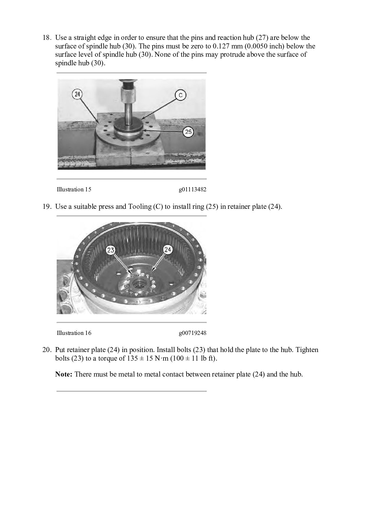
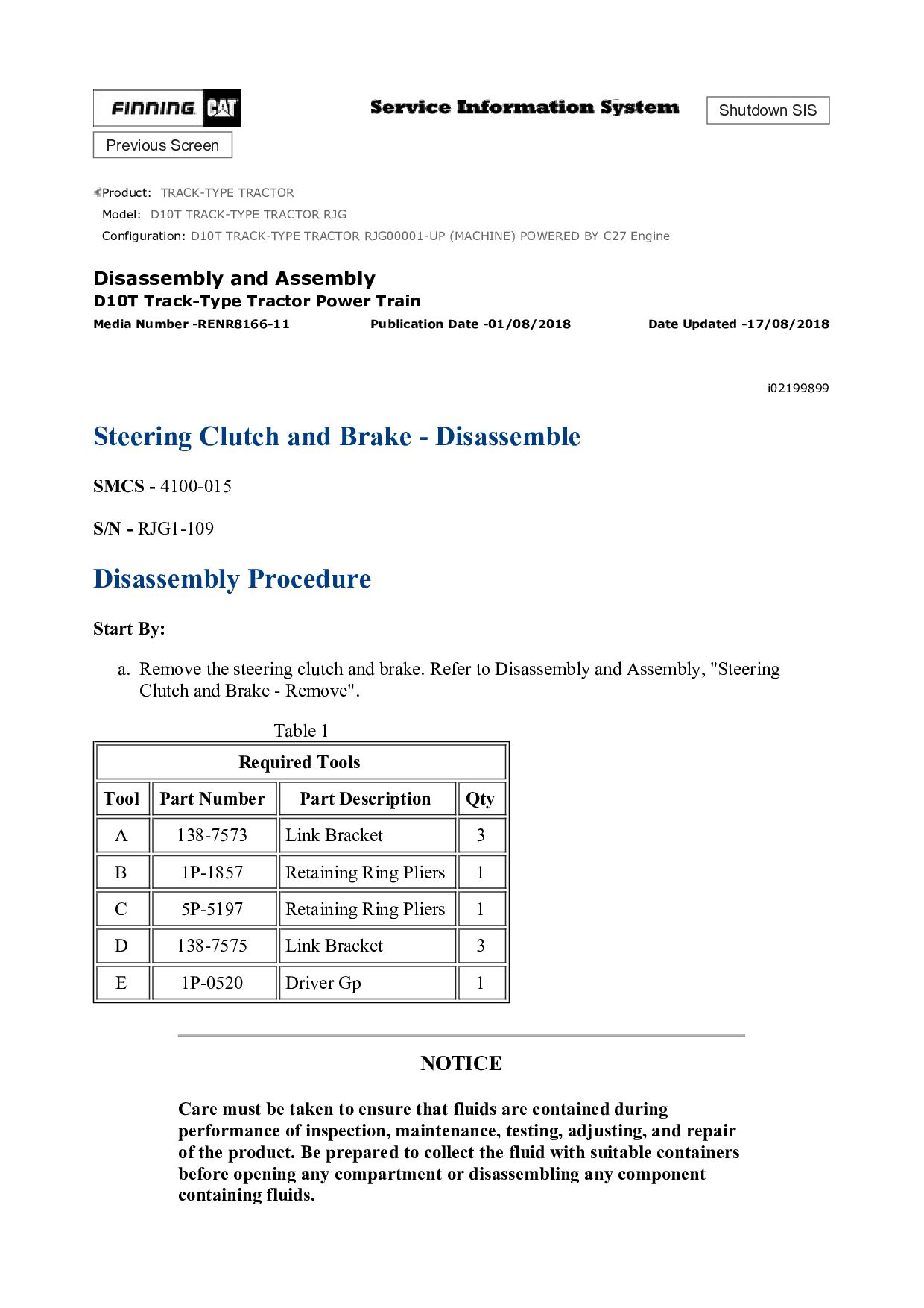
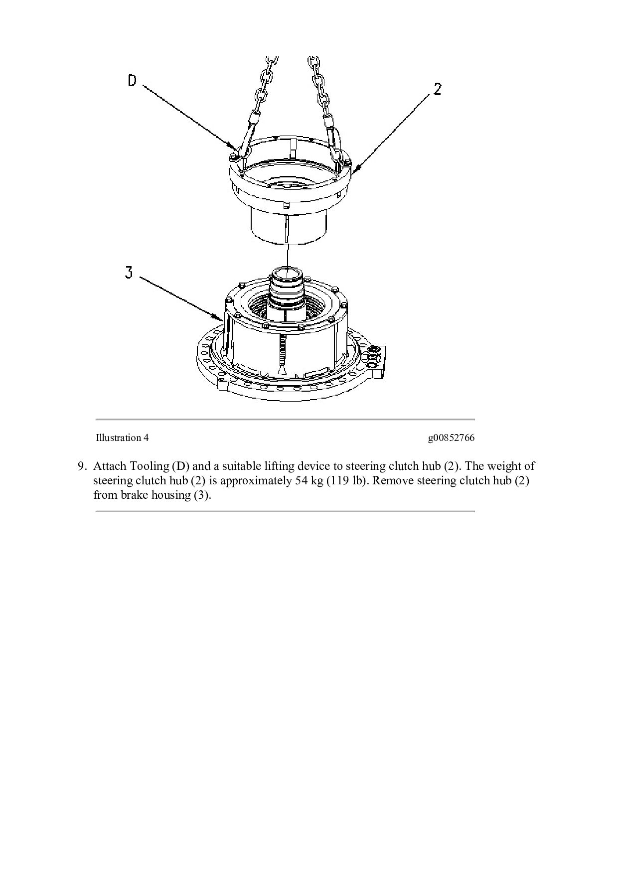
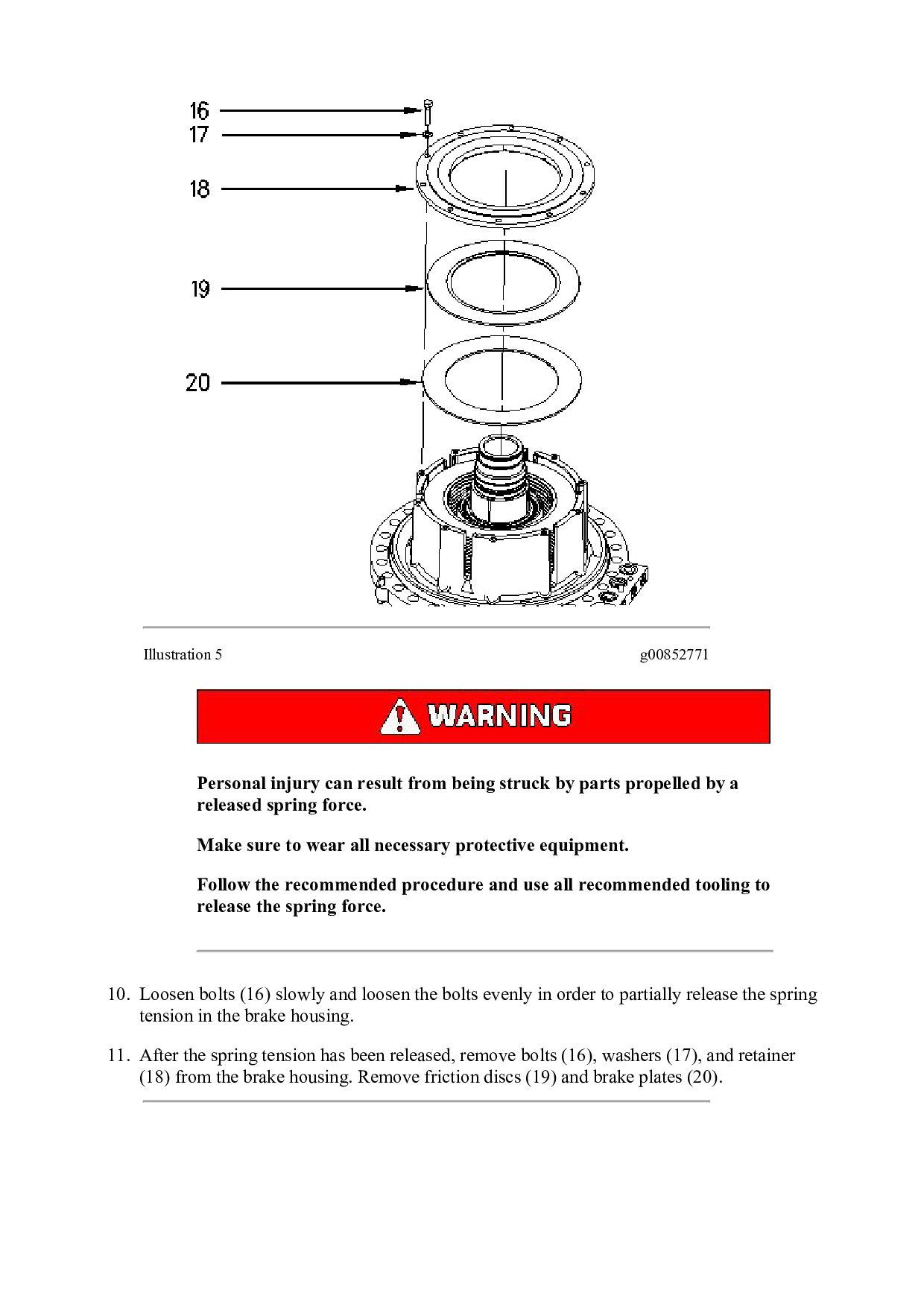
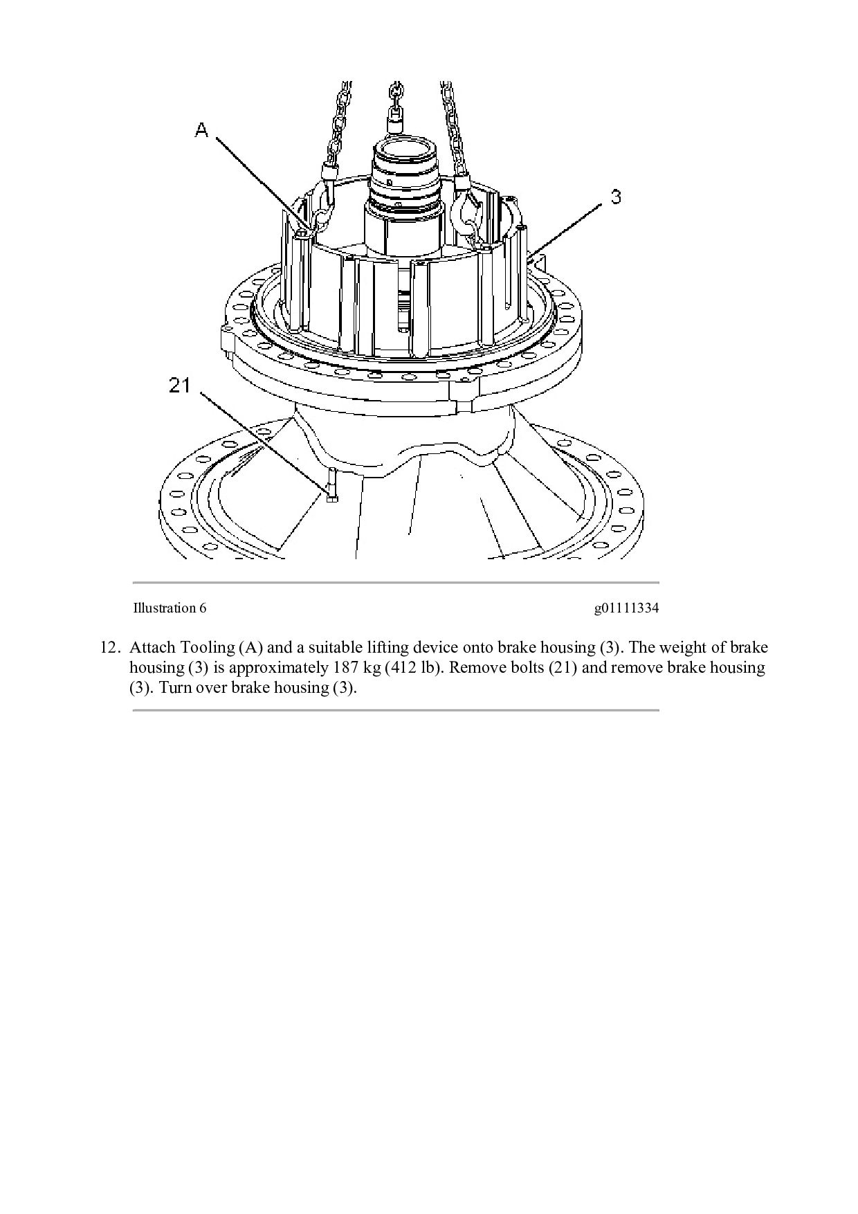
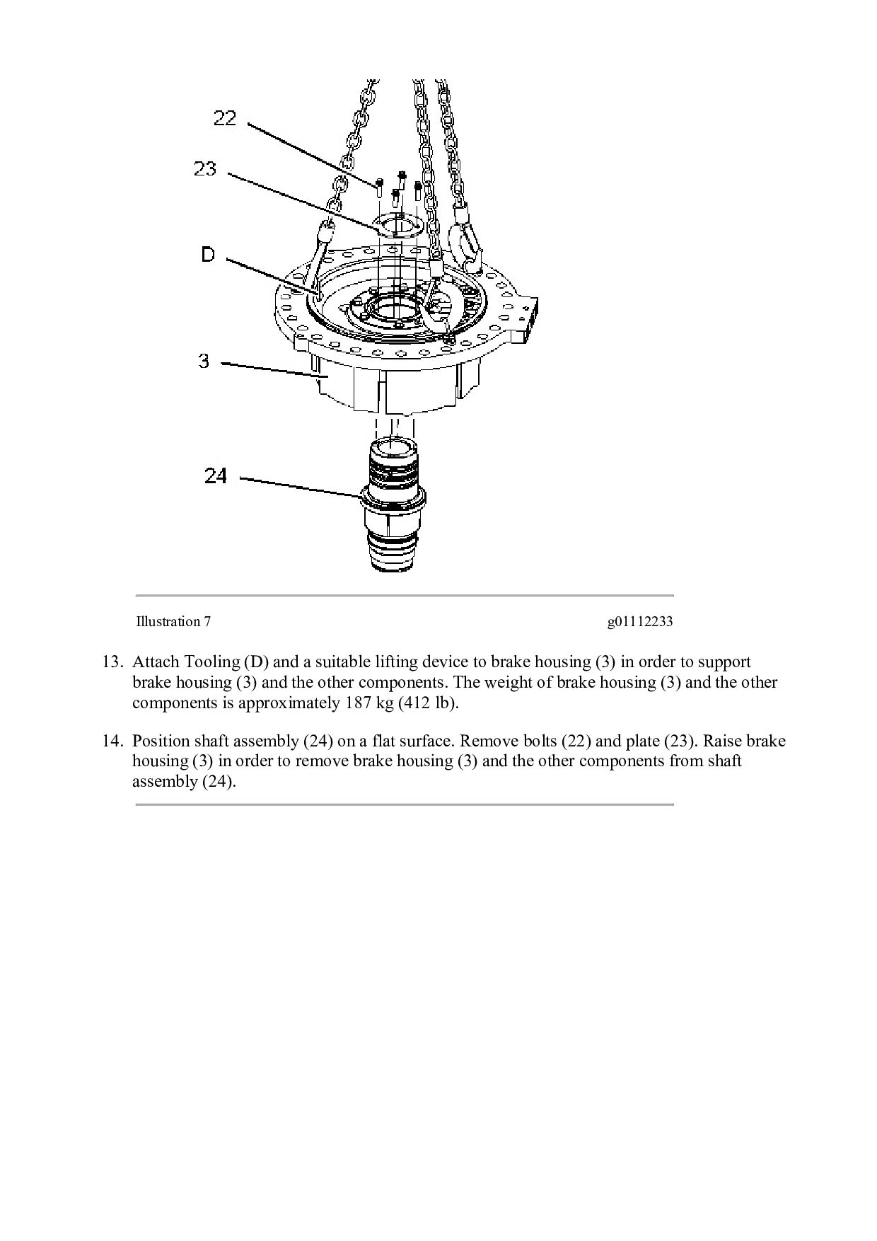
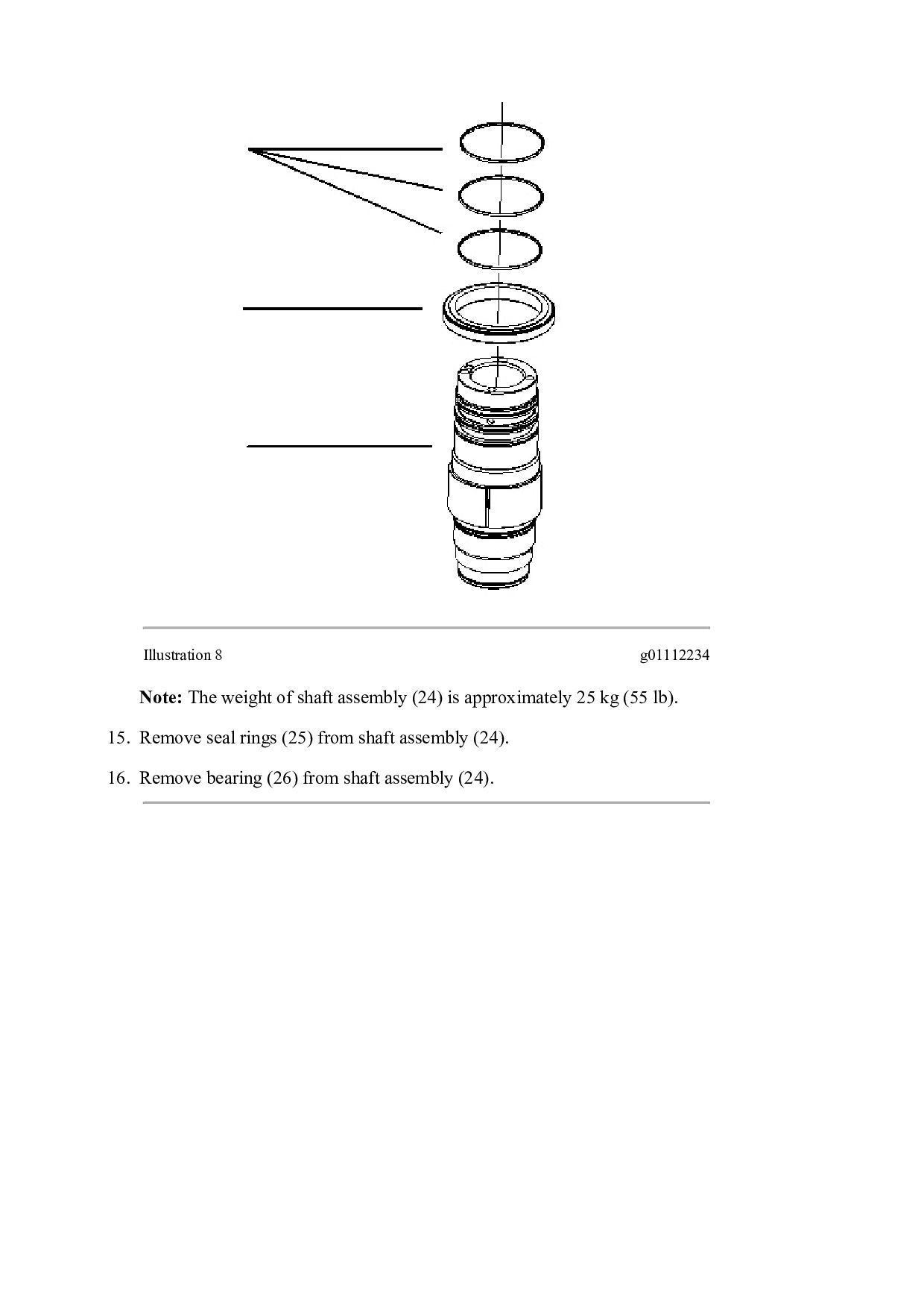
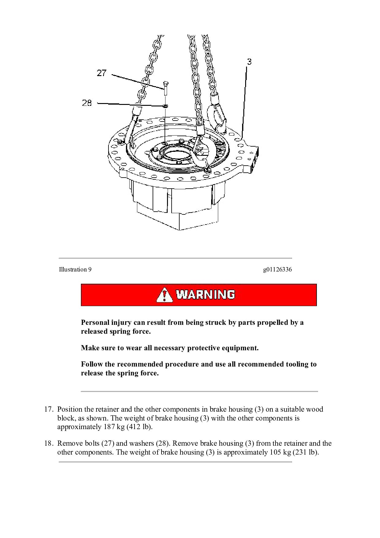
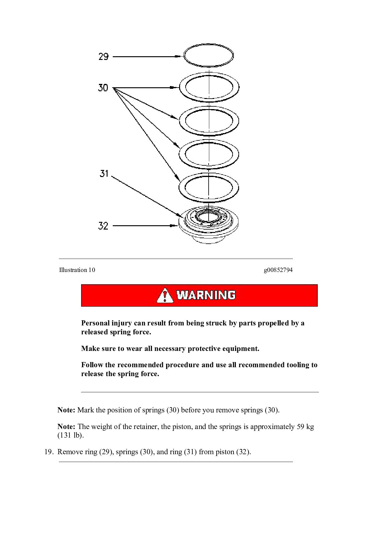
TRACTOR RJG Configuration: D10T TRACK-TYPE TRACTOR RJG00001-UP (MACHINE) POWERED BY C27 Engine Disassembly and Assembly D10T Track-Type Tractor Power Train Media Number -RENR8166-11 Publication Date -01/08/2018 Date Updated -17/08/2018 i02206391 Steering Clutch and Brake - Remove SMCS - 4100-011 Removal Procedure Start By: a. Separate the tracks. Refer to Disassembly and Assembly, "Track - Separate". b. Remove the axles. Refer to Disassembly and Assembly, "Axle - Remove". Table 1 Required Tools Tool Part Number Description Qty A 5P-8622 Shackle 1 151-2816 Plate 1 142-1664 Lifting Bracket 1 142-1666 Bracket 1 NOTICE Care must be taken to ensure that fluids are contained during performance of inspection, maintenance, testing, adjusting, and repair of the product. Be prepared to collect the fluid with suitable containers before opening any compartment or disassembling any component containing fluids.
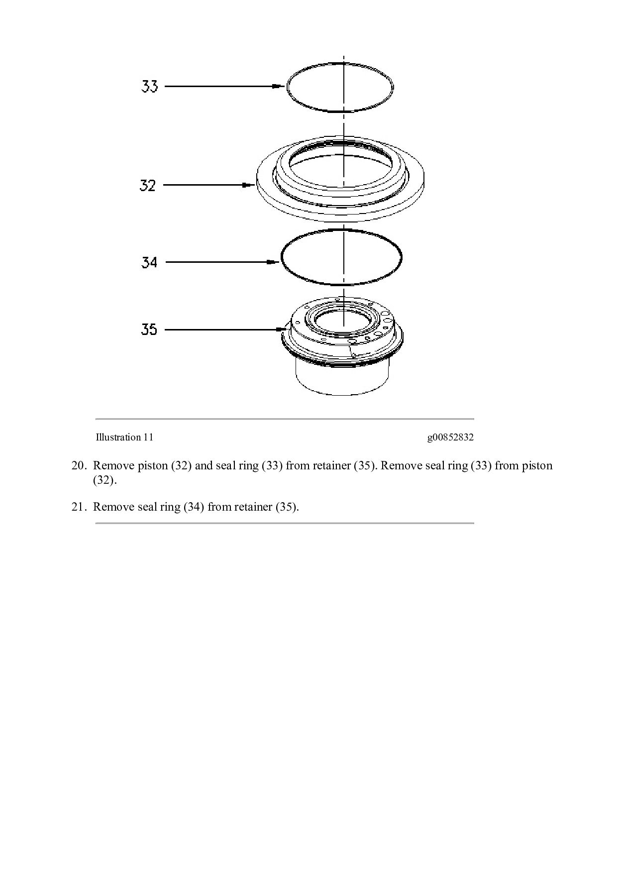
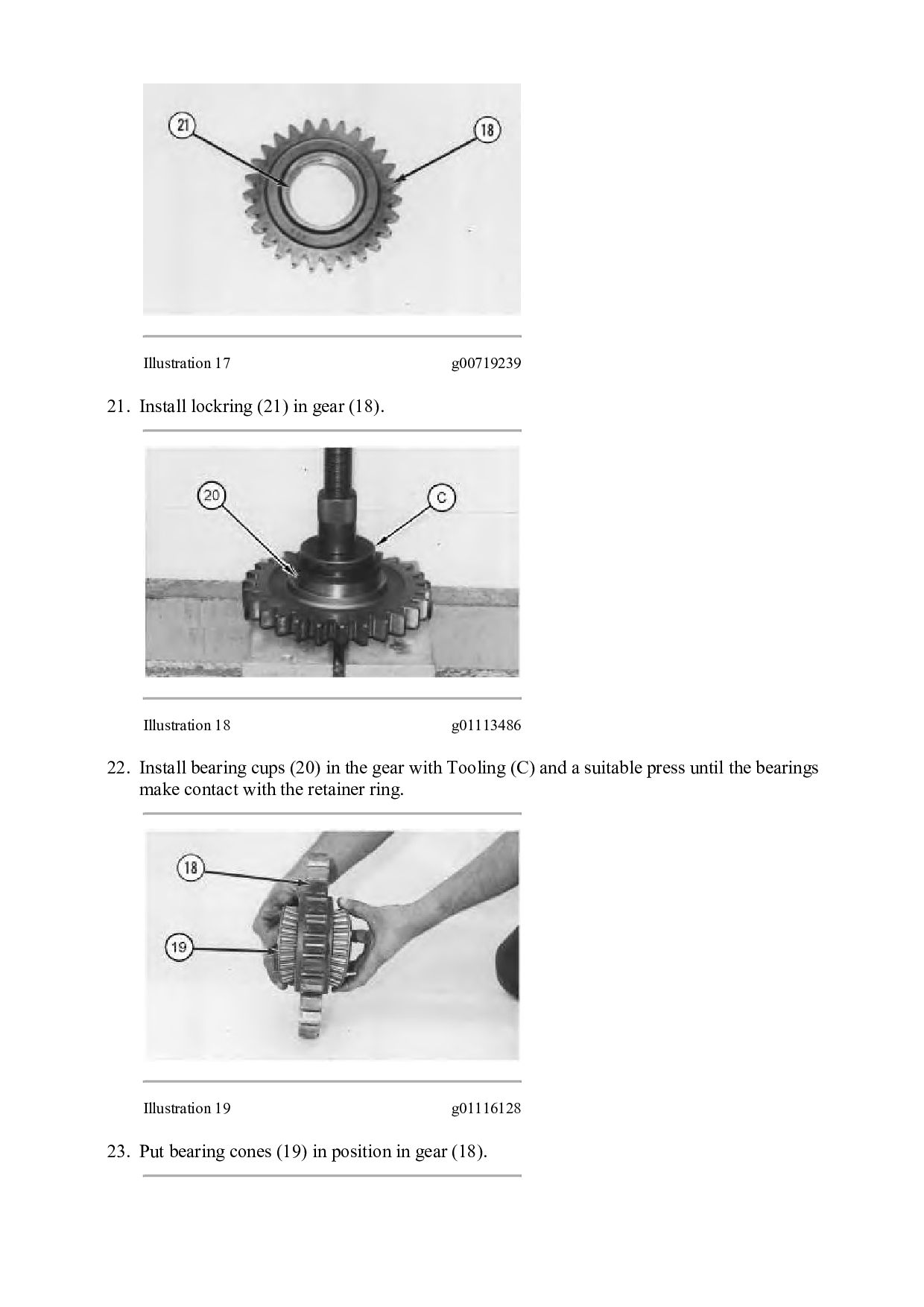
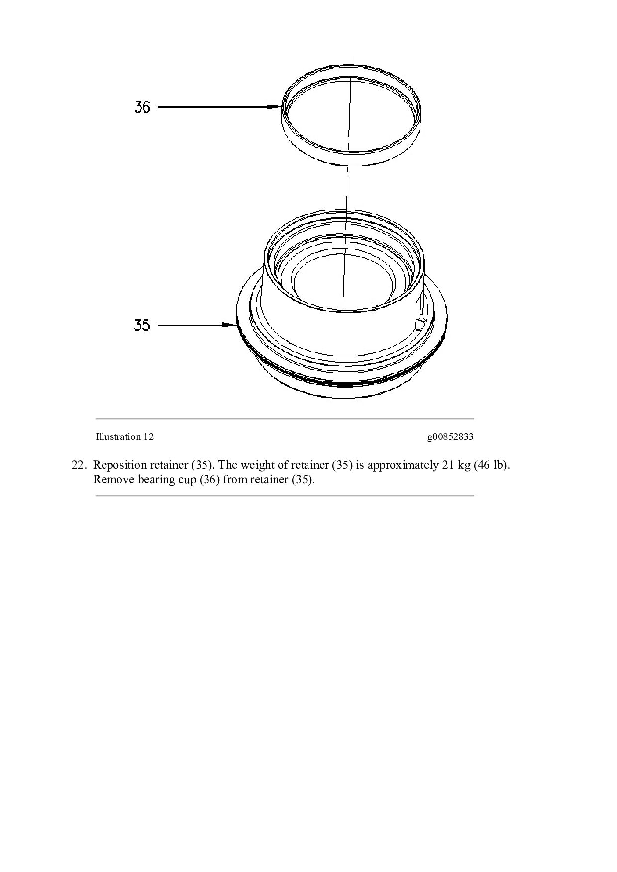
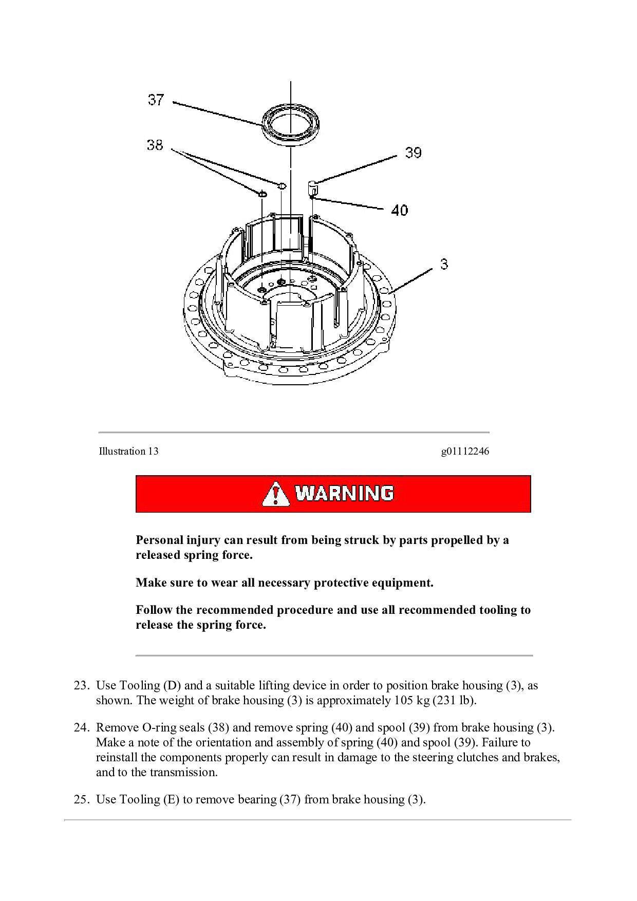
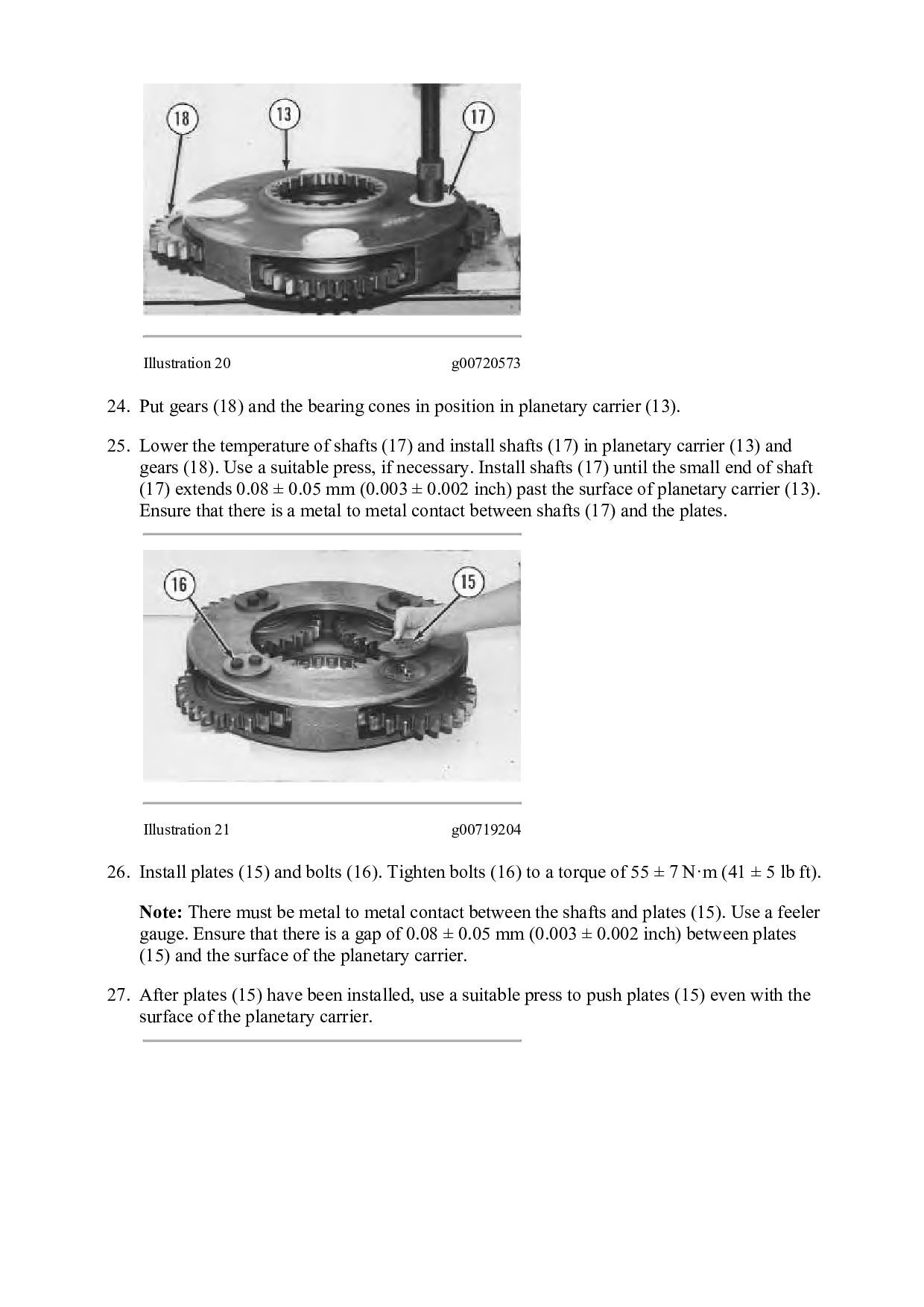
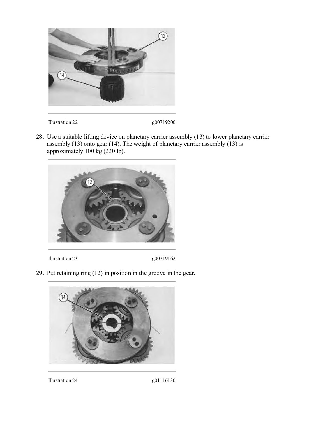
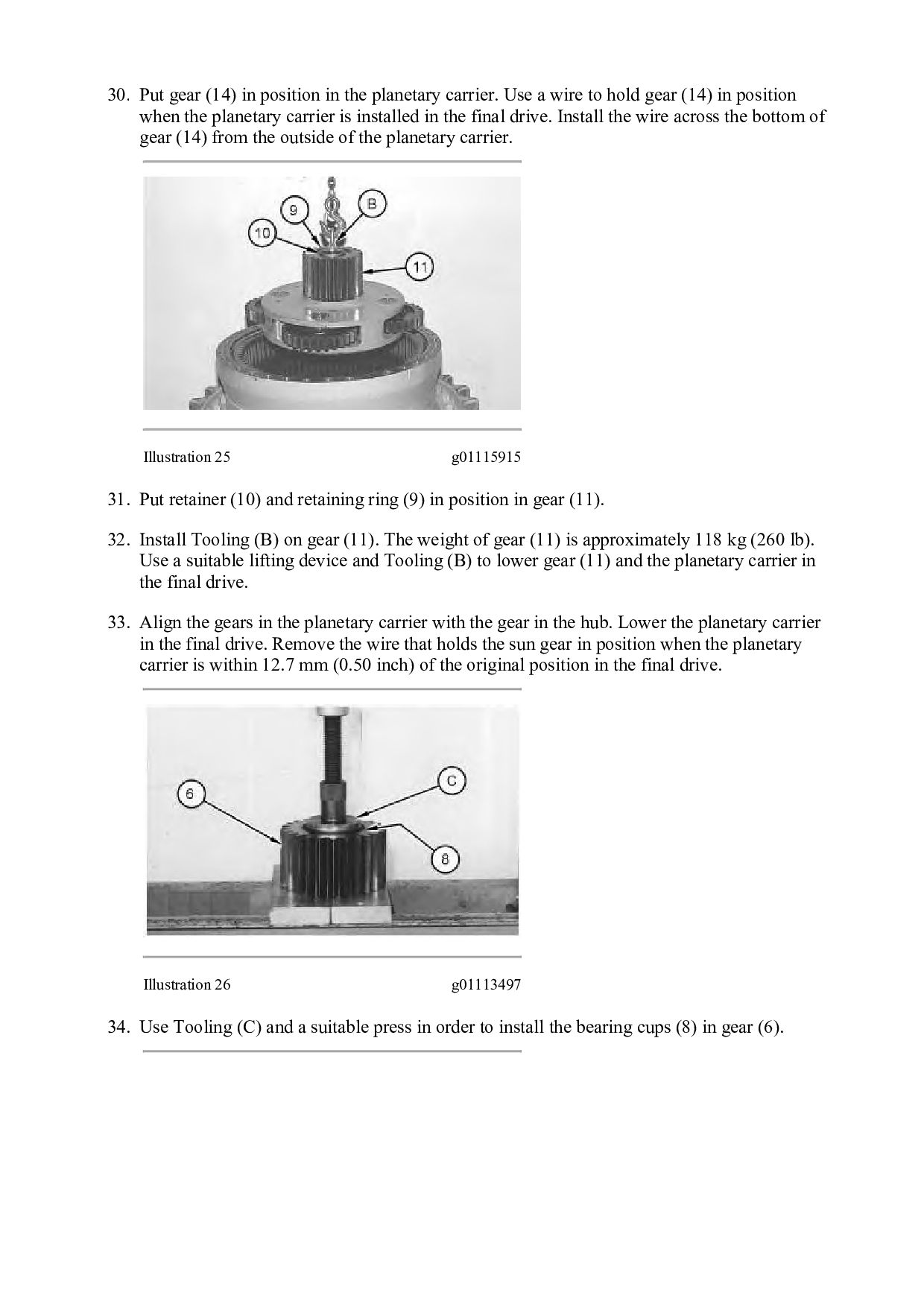
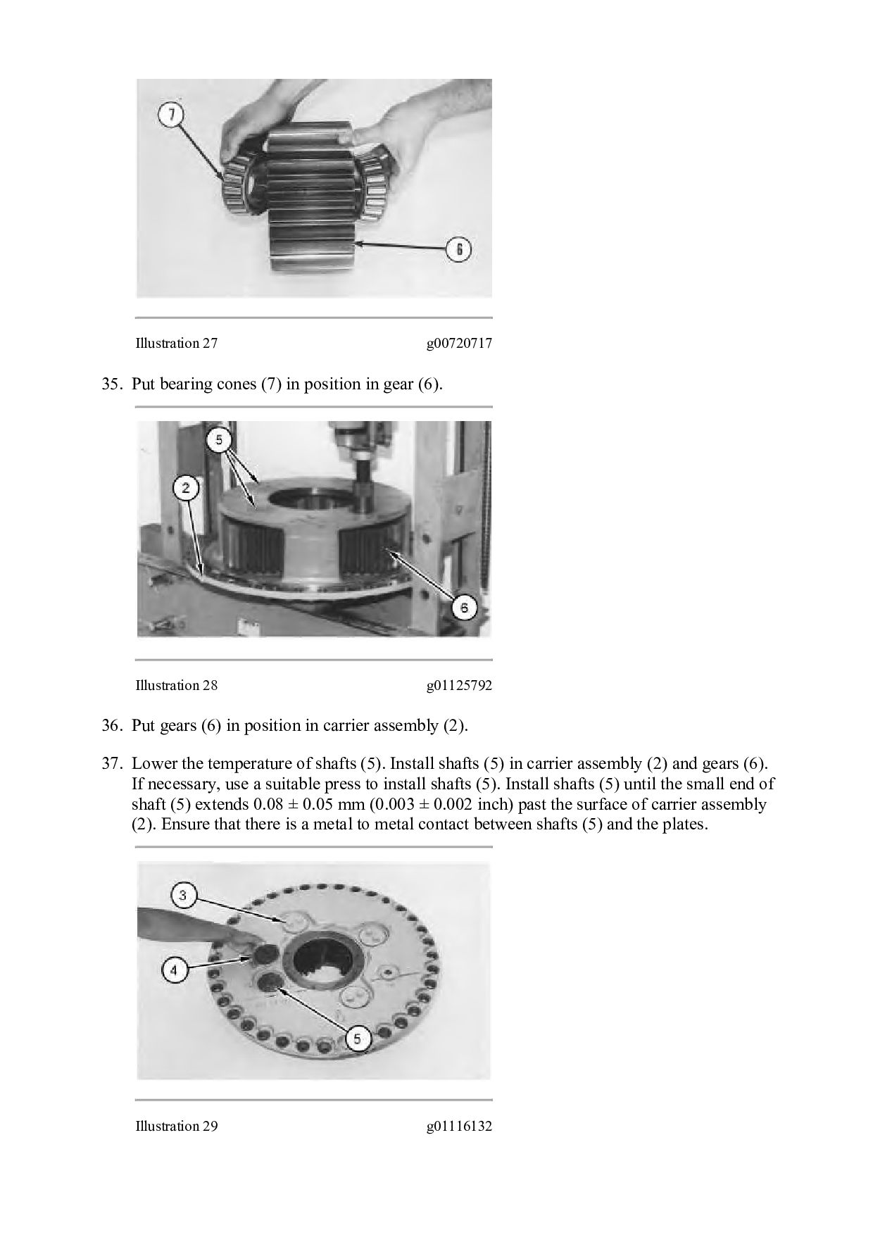
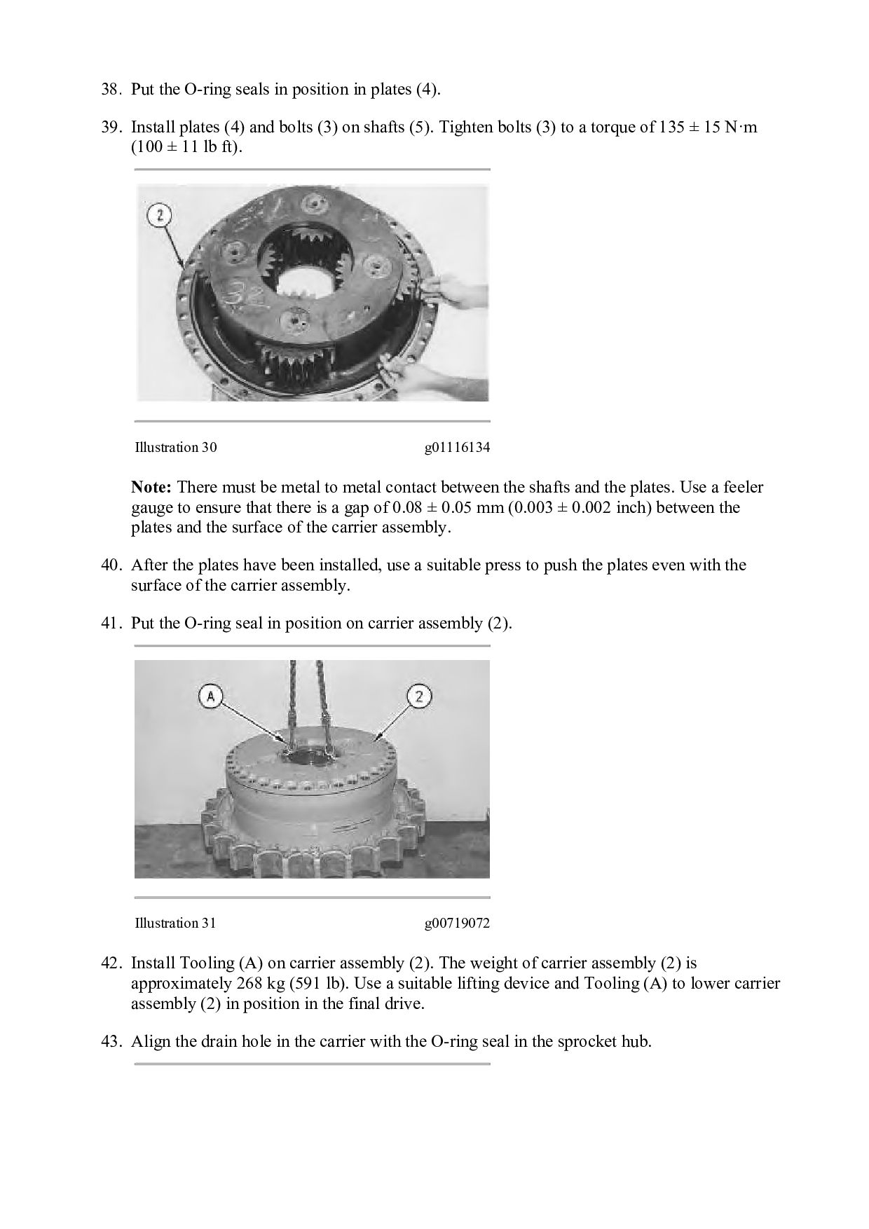
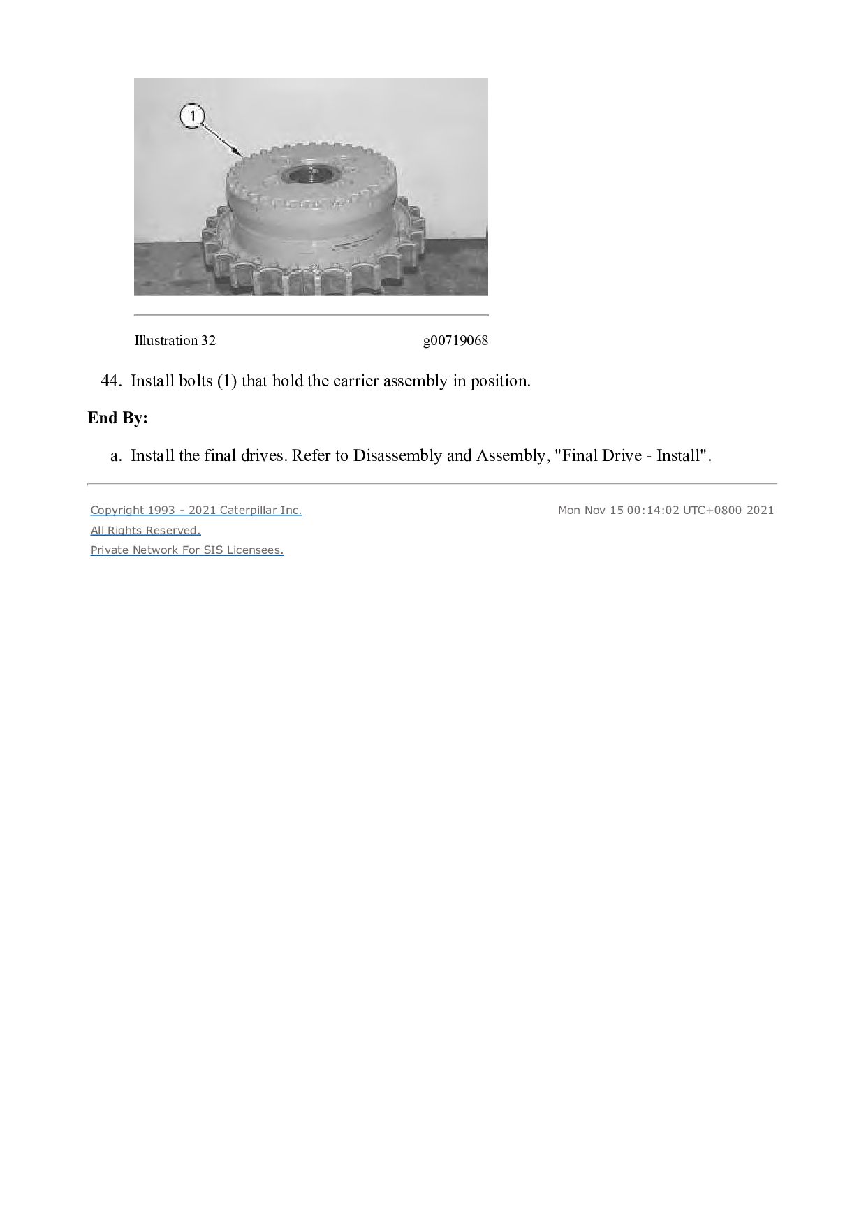