Upgrade to Pro — share decks privately, control downloads, hide ads and more …

Caterpillar_Cat_D6H_TRACK-TYPE_TRACTOR__Prefix_4LG__Service_Repair_Manual__4LG00001-03999_.pdf

dcfv
May 21, 2024
3

 Caterpillar_Cat_D6H_TRACK-TYPE_TRACTOR__Prefix_4LG__Service_Repair_Manual__4LG00001-03999_.pdf

dcfv

May 21, 2024
Tweet

More Decks by dcfv

Transcript

  1. Shutdown SIS Previous Screen Product: TRACK-TYPE TRACTOR Model: D6H TRACK-TYPE

    TRACTOR 4LG Configuration: D6H & D6H LGP TRACTORS / POWER SHIFT / 4LG00001-03999 (MACHINE) POWERED BY 3306 ENGINE Disassembly and Assembly D6H TRACTOR POWER TRAIN Media Number -SENR3242-03 Publication Date -01/11/2004 Date Updated -10/01/2017 SENR32420015 Steering Clutches and Brakes SMCS - 4100-016; 4100-015 Disassemble Steering Clutches and Brakes Start By: a. separate final drive from steering clutch and brake The brake group contains springs that are under compression. To prevent possible personal injury from flying parts, the brake group
  2. must be disassembled exactly as the following steps describe. Do

    not remove bolts (2) until after bolts (3) are slowly loosened and removed. 1. Remove the four bolts and plate (1) from the steering clutch and brake assembly. Do not remove bolts (2) at this time. 2. Install tooling (A), and attach a hoist. The weight of brake group (4) is 159 kg (350 lb). Remove brake group (4) from steering clutch group (5). To prevent possible personal injury from flying parts, make sure bolts (2) are tight before bolts (3) are removed. Bolts (3) are long enough to release the spring pressure behind retainer (6) as long as bolts (2) are installed. 3. Turn brake group (4) over. Evenly loosen 10 bolts (3) to release the spring pressure behind retainer (6). Remove bolts (3) and retainer (6).
  3. 4. Remove four discs (7) and the three plates from

    brake housing (4). 5. Remove O-ring seal (8) from the brake group. 6. Turn the brake group over, and install tooling (A). The weight of brake housing (4) is 73 kg (161 lb). Remove seven bolts (2). Use a soft hammer, and remove brake housing (4) from the retainer. 7. Remove ring (9) and spring (11) from retainer (10). 8. Remove ring (12) and piston (13) from the retainer. 9. Remove the seal ring from the inner diameter of piston (13). 10. Remove seal ring (15) from retainer (10).
  4. 11. Remove two ball bearings (14), one from each side

    of retainer (10). 12. Remove two O-ring seals (16) from the brake housing. 13. The weight of the steering clutch group is 159 kg (350 lb). Remove four bolts (18) and hub (17). 14. Use tool (B), and remove retaining ring (21). 15. Remove plate (20) and bearing (19) from the steering clutch group. 16. Remove the 10 bolts and the retainer. 17. Remove five discs (22) and the four plates from housing (23).
  5. 18. Install tooling (C) into the piston. The weight of

    piston (24) is 19.1 kg (42 lb). Remove piston (24) from housing (23). 19. Remove the seal ring from the inner diameter of piston (24). 20. Install tooling (A), and attach a hoist. The weight of housing (23) is 33.6 kg (74 lb). The weight of hub assembly (25) is 21 kg (46 lb). Raise the housing and hub assembly together, and remove the wood blocks. 21. Lower housing (23), and remove hub assembly (25). 22. Turn housing (23) over, and remove ring (26).
  6. https://www.aservicemanualpdf.com/ My Dear Friend! Thank you very much for visiting.

    Full manual if required, please enter the following URL into your browser. https://www.aservicemanualpdf.com/
  7. 23. Use tool (B), and remove retaining ring (27) from

    hub assembly (25). 24. Remove three seal rings (28) from the hub assembly. 25. Remove O-ring seal (30) from hub assembly (25). 26. Use tooling (D) and a press, and remove plate (29) from the hub assembly. Assemble Steering Clutches And Brakes
  8. 1. Lower the temperature of two bearings (1). Install two

    bearings (1), one in each side of retainer (2). 2. Install seal ring (3) on retainer (2). 3. Install seal ring (5) in piston (4). 4. Put piston (4) in position on retainer (2). 5. Put ring (6) in position on piston (4). 6. Put spring (7) in position on ring (6) and piston (4). Spring (7) goes with the concave side up. 7. Put ring (8) in position on spring (7). 8. Install two O-ring seals (9) on brake housing (10).
  9. 9. Install tooling (A) onto brake housing (10). Attach a

    hoist, and put the brake housing in position on retainer (2), and install the seven bolts that hold it. NOTE: A disc assembly has friction material on both sides. A plate is a smooth steel plate and does not have friction material on either side. Put clean oil on all disc assemblies and plates before assembly. 10. Turn the brake housing over. Put steering clutch hub (11) in position to align the discs. Install four discs (12) and the three plates into the housing. Alternate installation of the discs and plates. Start with a disc and end with a disc. 11. Put retainer (14) in position on the discs and brake housing. NOTICE Make sure the disc assemblies do not get between retainer (14) and the brake housing when the bolts are tightened. 12. Install bolts (13) and snug evenly, but do not tighten. Bolts (13) put the spring under compression. Bolts (13) should not be tightened now so the brake discs can be aligned with the steering clutch housing splines in Step 28.
  10. 13. Remove steering clutch hub (11) from the brake housing.

    14. Make sure the smooth side of plate (16) is toward the splines on hub assembly (15). Use tooling (B) and a press, and install plate (16) onto hub assembly (15). 15. Install seal ring (17) onto plate (16). 16. Use tool (C), and install retaining ring (18). Figure 1. Correct Method To Make (Non-Metal) New Seal Rings Rings Ready For Installation.
  11. Figure 2. Wrong Method To Make (Non-Metal) New Seal Rings

    Ready For Installation. NOTICE New seal rings must be preloaded before they are installed to prevent them from being damaged or broken when the clutch housing is installed. There is a correct method to preload new seal rings prior to installation. Place your hands on each end of the seal ring, and pull (wind) the ends several inches past each other or until they almost make contact. See Figure 1. Use care to keep the ring shaped like a circle. This will make an even bend (or ring "set") all around the ring. When the seal ring is in the groove of the hub, the ends must butt together lightly. Do not bend the seal ring as shown in Figure 2. This does not make an even bend all the way around the ring. Do not attempt to use this method to preload a use seal ring. Also, do not use this procedure for cast iron seal rings. This will cause used or cast iron seal rings to break. 17. Install three seal rings (19) onto the hub assembly. 18. Install ring (20) into steering clutch housing (21).
  12. 19. Use tooling (A) and a hoist, and put housing

    (21) on blocks as shown. Put hub assembly (15) in position in housing (21). 20. Install seal ring (22) in piston (23). 21. Install tooling (D) on piston (23). Put piston (23) in position in housing (21). 22. Heat plate (24) to a maximum temperature of 135° C (275° F). Install bearing (25) into plate (24). 23. Install plate (24) and bearing (25) onto hub assembly (15). 24. Use tooling (C), and install retaining ring (26). 25. Put hub (11) in position, and install the four bolts that hold it.
  13. 26. Install five discs (27) and the four plates into

    the housing. Alternate installation of the discs and plates. Start with a disc and end with a disc. 27. Put retainer (28) in position, and install the 10 bolts that hold it to the housing. 28. Install tooling (A) to the brake housing, and attach a hoist. Align the brake discs with the splines on the steering clutch housing. Put brake group (29) in position on steering clutch group (30). Make sure seal rings are in the correct position so they do not get caught as the groups are assembled together. 29. Install plate (31) and four bolts.
  14. 30. Tighten bolts (13). Bolts (13) were installed in Step

    12 but not tightened so the brake discs could be aligned with the steering clutch housing splines when they were assembled together in Step 28. End By: a. connect final drive with steering clutch and brake Copyright 1993 - 2022 Caterpillar Inc. All Rights Reserved. Private Network For SIS Licensees. Tue Jan 25 15:55:31 UTC+0800 2022
  15. Shutdown SIS Previous Screen Product: TRACK-TYPE TRACTOR Model: D6H TRACK-TYPE

    TRACTOR 4LG Configuration: D6H & D6H LGP TRACTORS / POWER SHIFT / 4LG00001-03999 (MACHINE) POWERED BY 3306 ENGINE Disassembly and Assembly D6H TRACTOR POWER TRAIN Media Number -SENR3242-03 Publication Date -01/11/2004 Date Updated -10/01/2017 SENR32420016 Power Train Oil Filter SMCS - 3004-010; 3004-017 Remove And Install Power Train Oil Filter NOTE: The power train oil filter is located behind the hydraulic tank on the right platform. 1. Remove plug (1) under the right platform and drain the oil from the power train oil filter. Install the plug after the oil has drained. 2. Remove the operators seat. Remove the arm cushion and control console cover in the cab, on the right side.
  16. 3. Remove the bolts and disconnect two tube assembly flanges

    (3) from the filter. One of the flange bolts holds a wiring harness clip. 4. Disconnect wires (2) from the switch. 5. Remove the two bolts at each end and remove panel (4). 6. Install tooling (A) and attach a hoist. The weight of the power train oil filter is 25 kg (55 lb). Remove four bolts (5) and remove the power train oil filter. NOTE: The following Steps are for installation of the power train oil filter. 7. Use tooling (A) and a hoist and put the power train oil filter in position. Install four bolts (5). 8. Put the tube assembly flanges in position on the back of the filter and install the bolts. Make sure the wiring harness clip is fastened with one of the original flange bolts. 9. Connect wires (2) to the switch. 10. Install panel (4). 11. Install the right control console cover, the right arm cushion, and the operators seat.
  17. Disassemble And Assemble Power Train Oil Filter Start By: a.

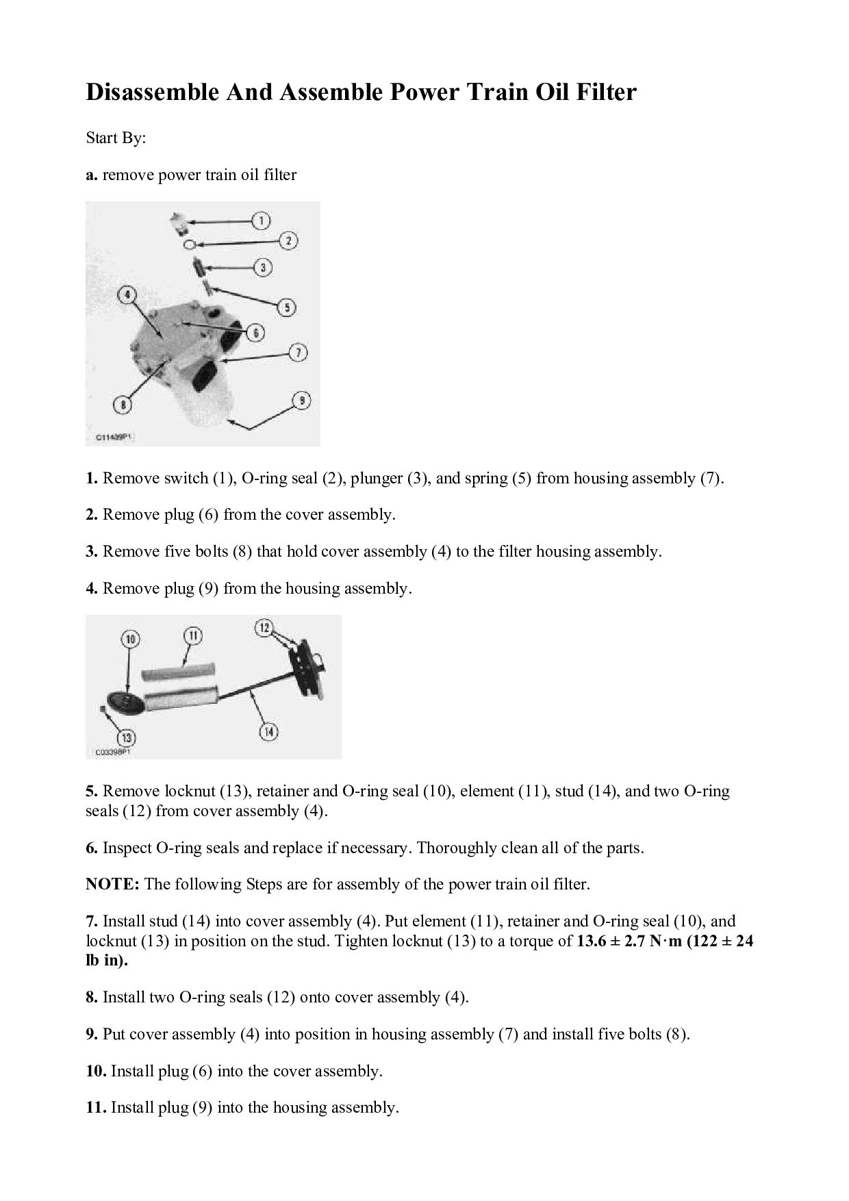
    remove power train oil filter 1. Remove switch (1), O-ring seal (2), plunger (3), and spring (5) from housing assembly (7). 2. Remove plug (6) from the cover assembly. 3. Remove five bolts (8) that hold cover assembly (4) to the filter housing assembly. 4. Remove plug (9) from the housing assembly. 5. Remove locknut (13), retainer and O-ring seal (10), element (11), stud (14), and two O-ring seals (12) from cover assembly (4). 6. Inspect O-ring seals and replace if necessary. Thoroughly clean all of the parts. NOTE: The following Steps are for assembly of the power train oil filter. 7. Install stud (14) into cover assembly (4). Put element (11), retainer and O-ring seal (10), and locknut (13) in position on the stud. Tighten locknut (13) to a torque of 13.6 ± 2.7 N·m (122 ± 24 lb in). 8. Install two O-ring seals (12) onto cover assembly (4). 9. Put cover assembly (4) into position in housing assembly (7) and install five bolts (8). 10. Install plug (6) into the cover assembly. 11. Install plug (9) into the housing assembly.
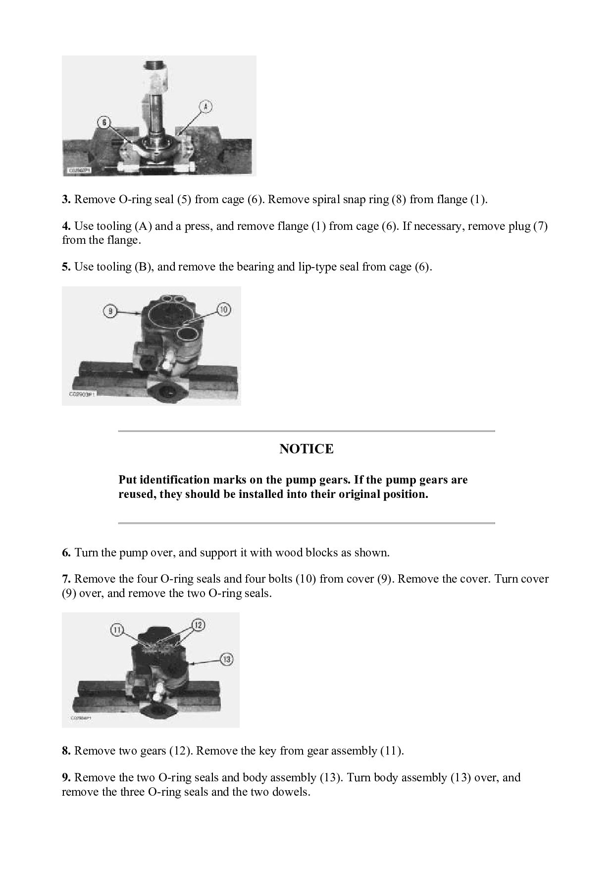
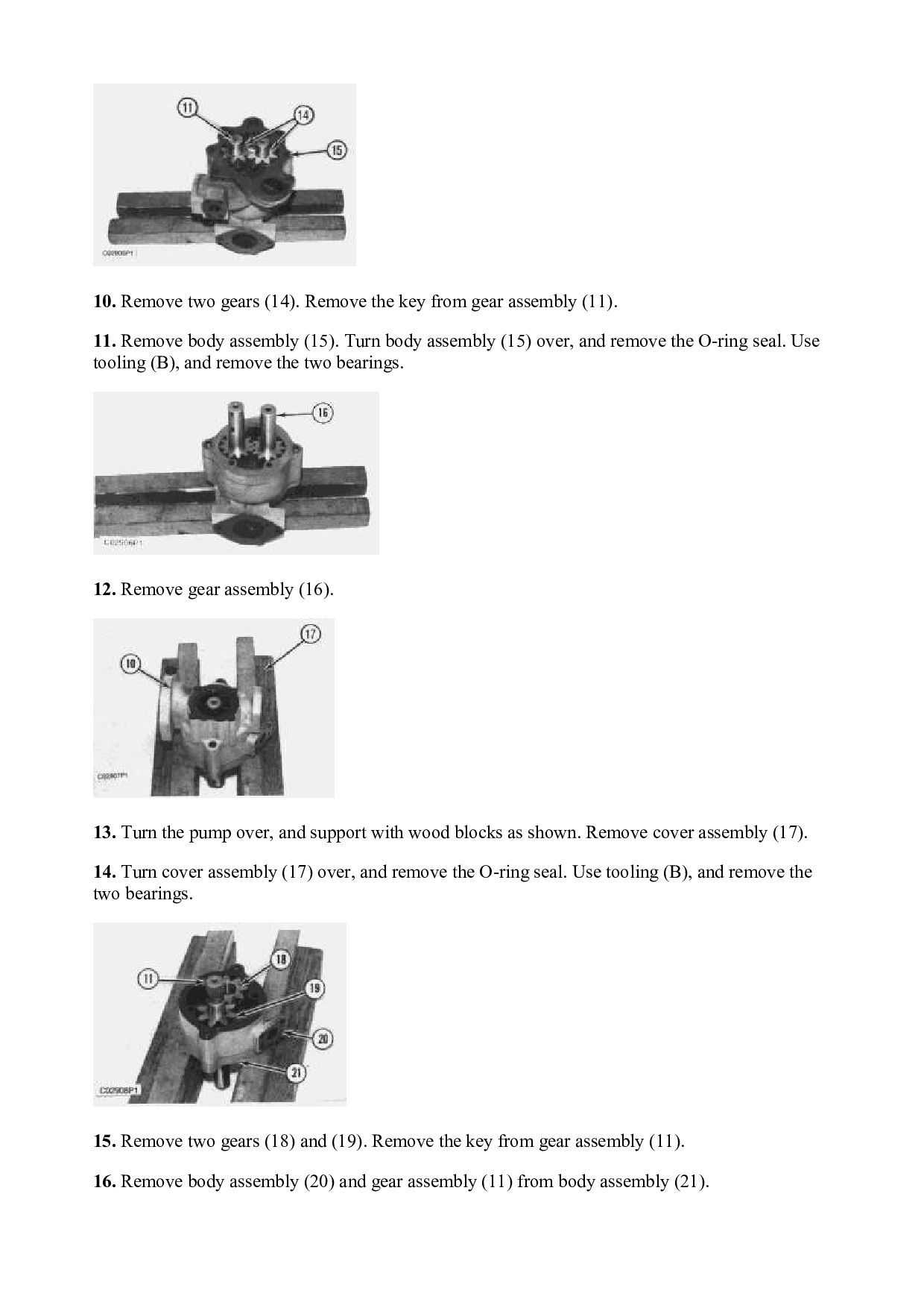
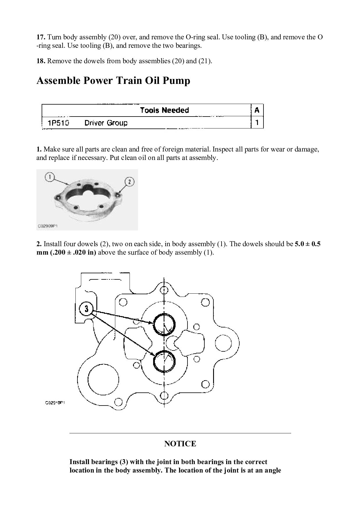
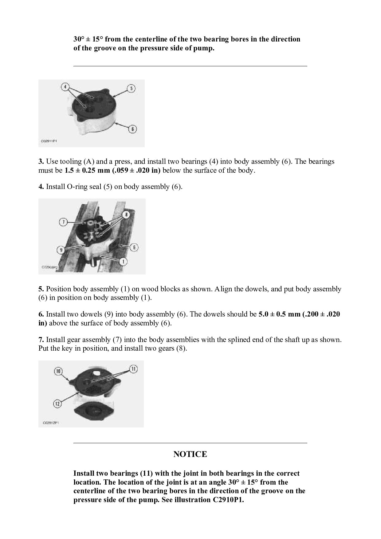
  18. 12. Install spring (5), plunger (3), O-ring seal (2), and

    switch (1) into housing assembly (7). End By: a. install power train oil filter Copyright 1993 - 2022 Caterpillar Inc. All Rights Reserved. Private Network For SIS Licensees. Tue Jan 25 15:56:27 UTC+0800 2022
  19. Shutdown SIS Previous Screen Product: TRACK-TYPE TRACTOR Model: D6H TRACK-TYPE

    TRACTOR 4LG Configuration: D6H & D6H LGP TRACTORS / POWER SHIFT / 4LG00001-03999 (MACHINE) POWERED BY 3306 ENGINE Disassembly and Assembly D6H TRACTOR POWER TRAIN Media Number -SENR3242-03 Publication Date -01/11/2004 Date Updated -10/01/2017 SENR32420017 Power Train Oil Pump SMCS - 3066-010; 3066-016 Remove And Install Power Train Oil Pump Start By: a. remove drive shaft (pump coupling) NOTE: The power train oil pump shown here is a three section pump that is used on the power shift vehicle. The direct drive vehicle is equipped with a four section power train oil pump. Except for the additional lines that must be disconnected and connected to the four section pump, the removal and installation procedures are the same for both pumps.
  20. 1. Put identification marks on the wires and disconnect them

    from switch (1). 2. Remove two bolts (6) that hold the tube assembly to the power train oil pump. 3. Disconnect hose assemblies (3) and (5) from the power train oil pump. 4. Install the 5P9736 Link Bracket [part of tooling (A)] to the ceiling of the cab, using the right side threaded hole. Attach the 8S9906 ratchet puller to the link bracket. 5. The weight of the direct drive four section power train oil pump is 50 kg (110 lb). The weight of the power shift three section power train oil pump is 39 kg (85 lb). Put a nylon strap around the pump and attach tooling (A). NOTICE Remove the plastic strap that fastens wiring harness (7) to the frame to prevent damage from the ratchet puller and pump. 6. Remove four bolts (2) and two nuts (4). Use tooling (A) and remove the pump. 7. Remove the four O-ring seals from the cover. NOTE: The following steps are for installation of the power train oil pump. 8. Use tooling (A) and put the power train oil pump in position. Install four bolts (2) and two nuts (4). 9. Connect hose assemblies (3) and (5) to the pump. Make sure the O-ring seals on the tube assembly are in position, and install two bolts (6). 10. Connect the wires to switch (1). 11. Check, and fill the power train system with oil. See the Operation and Maintenance Guide for the type of oil and capacity.
  21. End By: a. install drive shaft (pump coupling) Disassemble Power

    Train Oil Pump Start By: a. remove power train oil pump. NOTE: The power train oil pump used on the power shift machine is a three section pump. A four section pump is used on the direct drive machine. The four section pump has been illustrated here, but the disassembly and assembly procedures are similar for both pumps. To clarify any differences and for identification of the individual pump sections, see the Specification module, Form No. SENR3239. 1. Remove switch (3). Remove four bolts (2) and flange (1) with the cage from the pump. 2. Remove two bolts (4).
  22. 3. Remove O-ring seal (5) from cage (6). Remove spiral

    snap ring (8) from flange (1). 4. Use tooling (A) and a press, and remove flange (1) from cage (6). If necessary, remove plug (7) from the flange. 5. Use tooling (B), and remove the bearing and lip-type seal from cage (6). NOTICE Put identification marks on the pump gears. If the pump gears are reused, they should be installed into their original position. 6. Turn the pump over, and support it with wood blocks as shown. 7. Remove the four O-ring seals and four bolts (10) from cover (9). Remove the cover. Turn cover (9) over, and remove the two O-ring seals. 8. Remove two gears (12). Remove the key from gear assembly (11). 9. Remove the two O-ring seals and body assembly (13). Turn body assembly (13) over, and remove the three O-ring seals and the two dowels.
  23. 10. Remove two gears (14). Remove the key from gear

    assembly (11). 11. Remove body assembly (15). Turn body assembly (15) over, and remove the O-ring seal. Use tooling (B), and remove the two bearings. 12. Remove gear assembly (16). 13. Turn the pump over, and support with wood blocks as shown. Remove cover assembly (17). 14. Turn cover assembly (17) over, and remove the O-ring seal. Use tooling (B), and remove the two bearings. 15. Remove two gears (18) and (19). Remove the key from gear assembly (11). 16. Remove body assembly (20) and gear assembly (11) from body assembly (21).
  24. 17. Turn body assembly (20) over, and remove the O-ring

    seal. Use tooling (B), and remove the O -ring seal. Use tooling (B), and remove the two bearings. 18. Remove the dowels from body assemblies (20) and (21). Assemble Power Train Oil Pump 1. Make sure all parts are clean and free of foreign material. Inspect all parts for wear or damage, and replace if necessary. Put clean oil on all parts at assembly. 2. Install four dowels (2), two on each side, in body assembly (1). The dowels should be 5.0 ± 0.5 mm (.200 ± .020 in) above the surface of body assembly (1). NOTICE Install bearings (3) with the joint in both bearings in the correct location in the body assembly. The location of the joint is at an angle
  25. 30° ± 15° from the centerline of the two bearing

    bores in the direction of the groove on the pressure side of pump. 3. Use tooling (A) and a press, and install two bearings (4) into body assembly (6). The bearings must be 1.5 ± 0.25 mm (.059 ± .020 in) below the surface of the body. 4. Install O-ring seal (5) on body assembly (6). 5. Position body assembly (1) on wood blocks as shown. Align the dowels, and put body assembly (6) in position on body assembly (1). 6. Install two dowels (9) into body assembly (6). The dowels should be 5.0 ± 0.5 mm (.200 ± .020 in) above the surface of body assembly (6). 7. Install gear assembly (7) into the body assemblies with the splined end of the shaft up as shown. Put the key in position, and install two gears (8). NOTICE Install two bearings (11) with the joint in both bearings in the correct location. The location of the joint is at an angle 30° ± 15° from the centerline of the two bearing bores in the direction of the groove on the pressure side of the pump. See illustration C2910P1.
  26. Please write to us. Our email: [email protected] Please go to

    the homepage to get the full manual, or other brand PDF manuals. Home Site: aservicemanualpdf.com
  27. Thank you very much for your reading. Please Click Here.

    Then Get COMPLETE MANUAL. NO WAITING NOTE: If there is no response to click on the link above, please download the PDF document first and then click on it.
  28. 8. Use tooling (A) and a press, and install two

    bearings (11) into body assembly (10). The bearings must be 1.5 ± 0.25 mm (.059 ± .020 in) below the surface of the body. 9. Install O-ring seal (12) on body assembly (10). 10. Turn body assembly (10) over, and put it in position on body assembly (6). Make sure O-ring seal (12) stays in position when the body is turned over. 11. Turn the pump assembly over, and install gear assembly (13). NOTICE Install two bearings (15) with the joint in both bearings in the correct location. The location of the joint is at an angle 30° ± 15° from the centerline of the two bearing bores in the direction of the groove on the pressure side of the pump. See illustration C2910P1. 12. Use tooling (A) and a press, and install two bearings (15) into body assembly (14). The bearings must be 1.5 ± 0.25 mm (.059 ± .020 in) below the surface of the body.
  29. 13. Install O-ring seal (16) onto body assembly (14). 14.

    Turn body assembly (14) over, and put it in position on body assembly (1). Make sure O-ring seal (16) stays in position when the body assembly is turned over. 15. Put the key in position in the groove on gear assembly (7). Install two gears (17). 16. Install two dowels (19) in body assembly (18). The dowels should be 5.0 ± 0.5 mm (.200 ± .020 in) above the surface of body assembly (18). 17. Install three O-ring seals (20) onto body assembly (18). 18. Turn body assembly (18) over, and install it onto body assembly (14). Make sure three O-ring seals (20) stay in position. 19. Put the key in the groove in gear assembly (7). Install two gears (22). 20. Install two O-ring seals (21).
  30. 21. Install two O-ring seals (24) in cover (23). 22.

    Turn cover (23) over, and install it on body assembly (18). Install four bolts and washers (25). 23. Install the four O-ring seals on cover (23). 24. Put 7M7260 Liquid Gasket Material on the outer diameter of the lip-type seal. Use tool (A) and a press, and install the lip-type seal into cage (26). Put clean oil on the lip of the seal. 25. Use tool (A) and a press, and install the bearing into cage (26). 26. Clean the outer diameter of the plug that goes in flange (27), and put 7M7260 Liquid Gasket Material on it. Use tool (A), and install the plug until it is 1.25 ± 0.25 mm (.05 ± .010 in) below the surface of the flange.
  31. https://www.aservicemanualpdf.com/ My Dear Friend! Thank you very much for visiting.

    Full manual if required, please enter the following URL into your browser. https://www.aservicemanualpdf.com/