the motor drives and other required circuitry Establish a lower level of control for the basic locomotion of the lawnmower Integrate the setup with a higher level of control for decision making and path planning Make the robot autonomous to a certain degree by implementing an obstacle avoidance algorithm
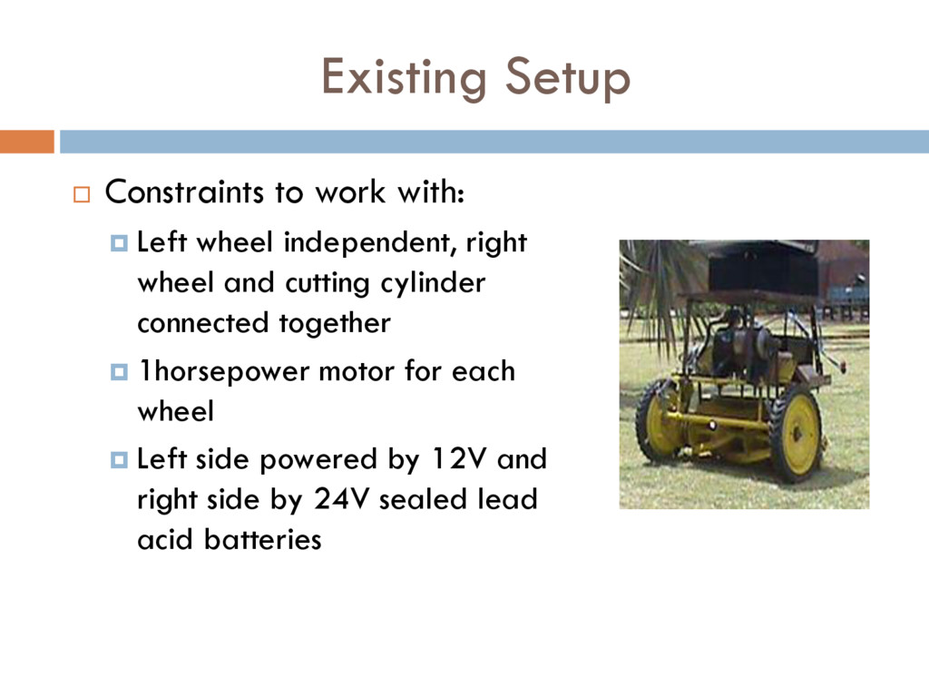
independent, right wheel and cutting cylinder connected together 1horsepower motor for each wheel Left side powered by 12V and right side by 24V sealed lead acid batteries
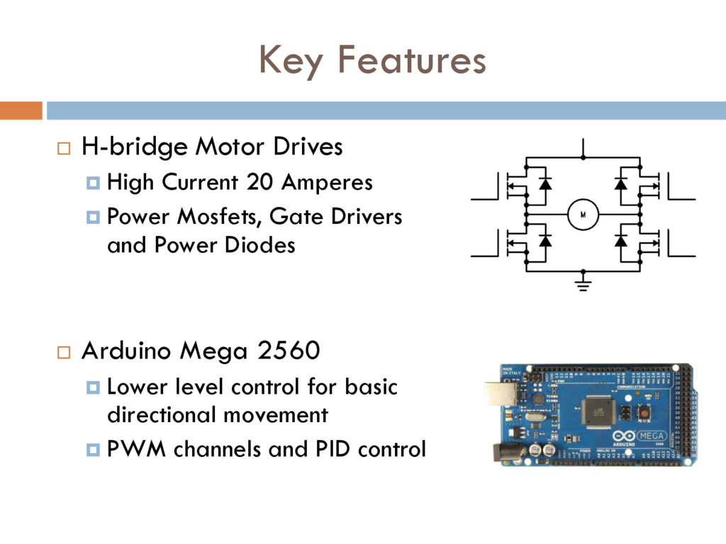
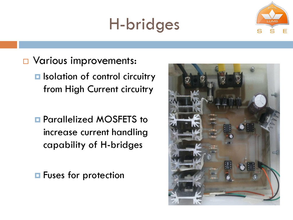
Amperes Power Mosfets, Gate Drivers and Power Diodes Arduino Mega 2560 Lower level control for basic directional movement PWM channels and PID control
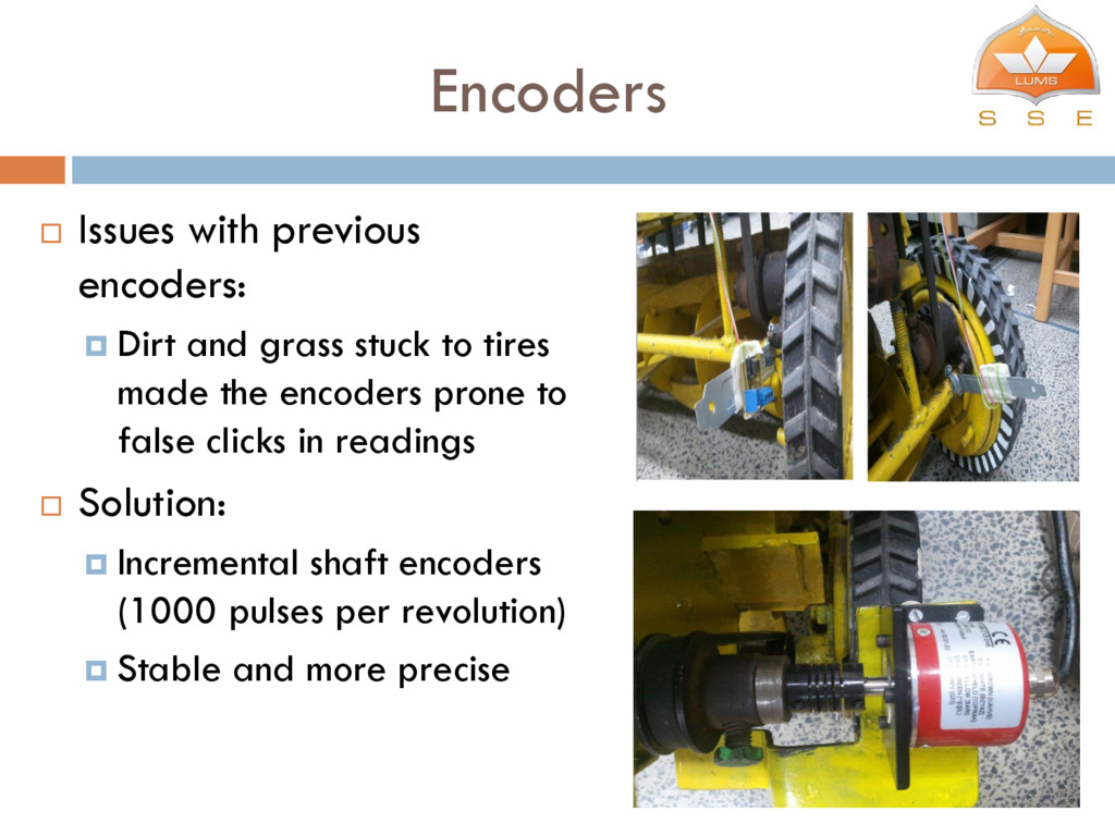
stuck to tires made the encoders prone to false clicks in readings Solution: Incremental shaft encoders (1000 pulses per revolution) Stable and more precise
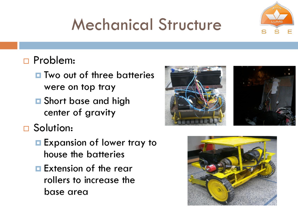
were on top tray Short base and high center of gravity Solution: Expansion of lower tray to house the batteries Extension of the rear rollers to increase the base area
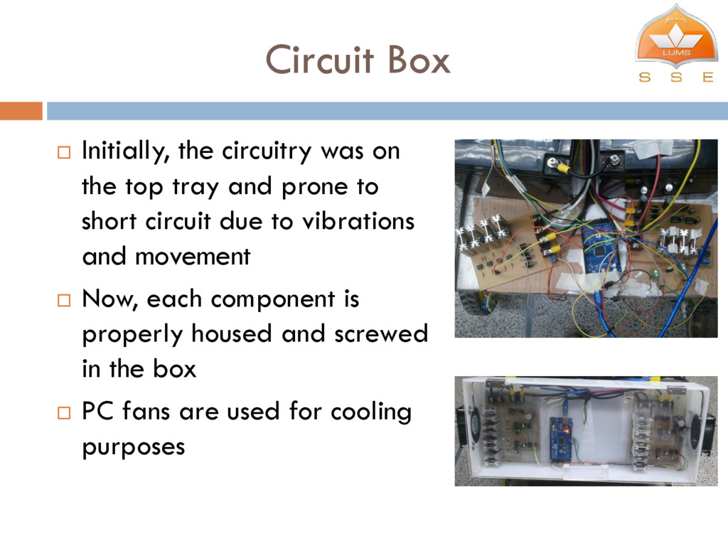
tray and prone to short circuit due to vibrations and movement Now, each component is properly housed and screwed in the box PC fans are used for cooling purposes
Changed the bearings of the rotating cutter cage Cleaned and greased the inner rack and pinion lining of the wheels Result Wheels and cutter cage rotate more easily and draw less current
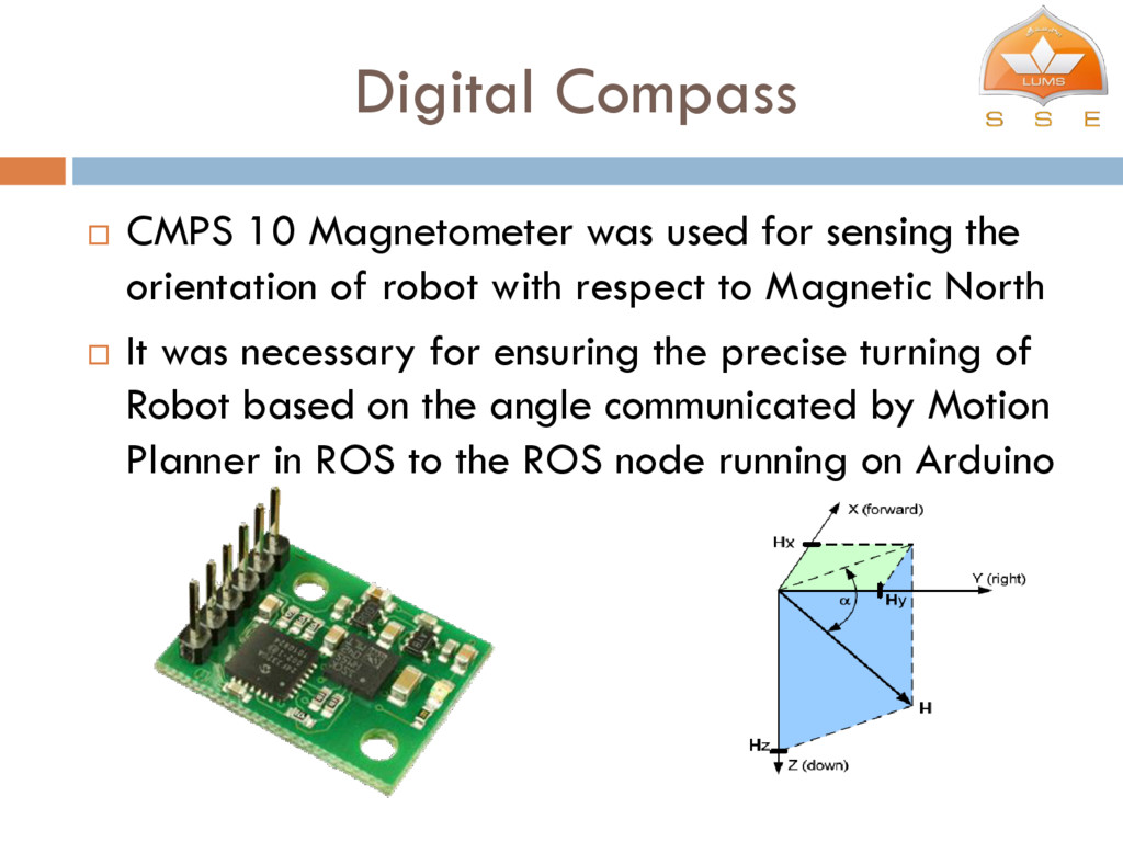
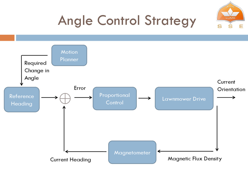
the orientation of robot with respect to Magnetic North It was necessary for ensuring the precise turning of Robot based on the angle communicated by Motion Planner in ROS to the ROS node running on Arduino
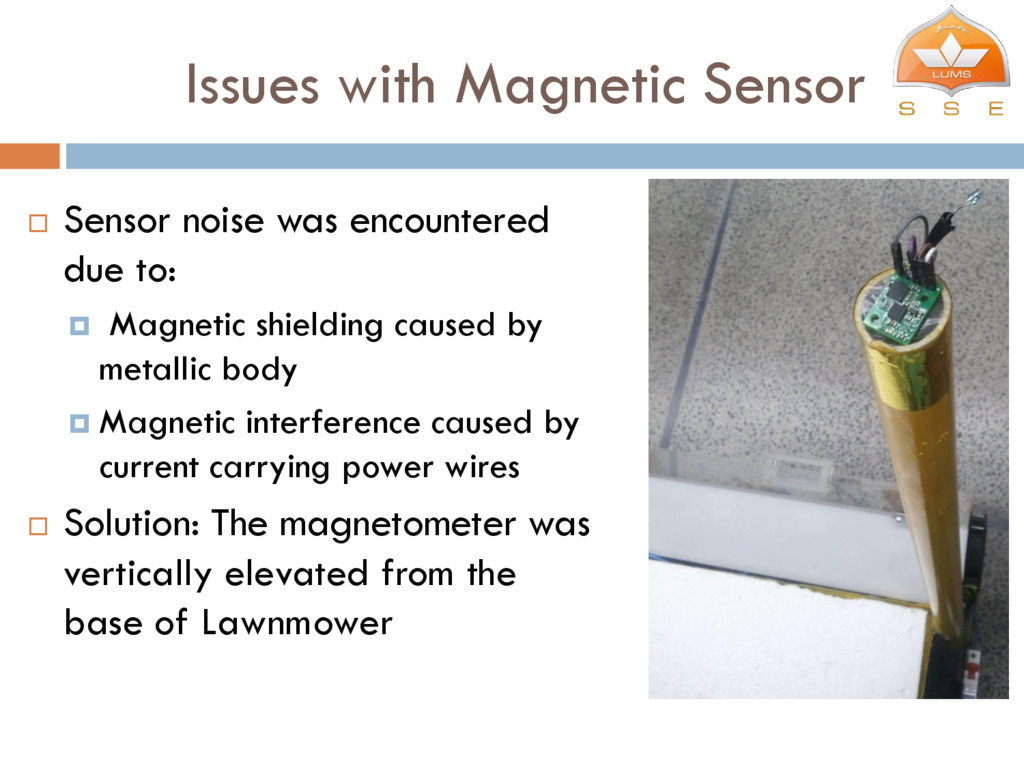
to: Magnetic shielding caused by metallic body Magnetic interference caused by current carrying power wires Solution: The magnetometer was vertically elevated from the base of Lawnmower
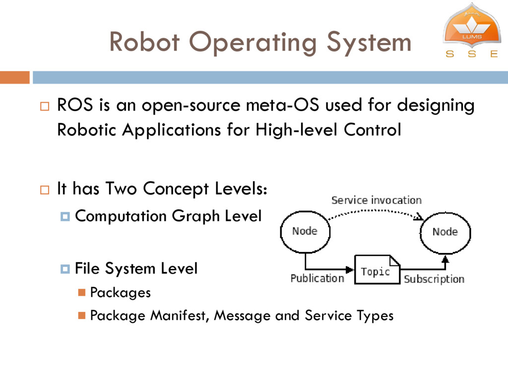
for designing Robotic Applications for High-level Control It has Two Concept Levels: Computation Graph Level File System Level Packages Package Manifest, Message and Service Types
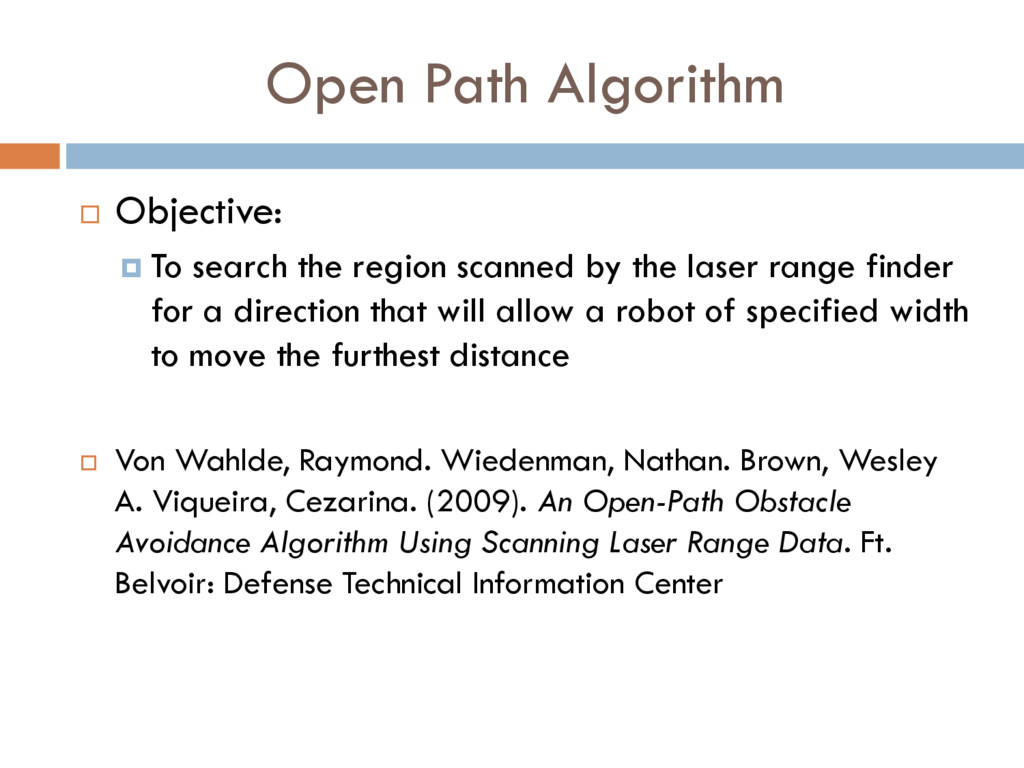
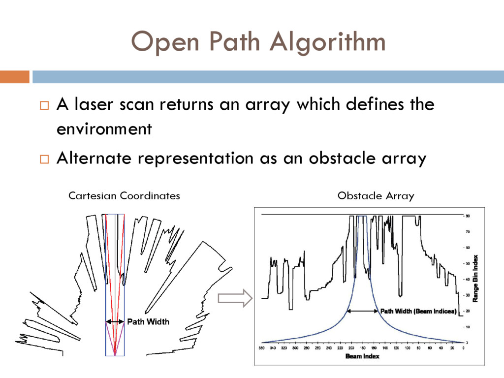
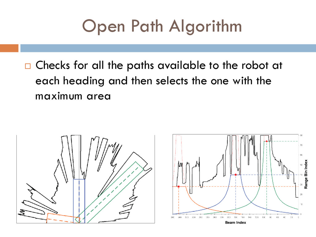
scanned by the laser range finder for a direction that will allow a robot of specified width to move the furthest distance Von Wahlde, Raymond. Wiedenman, Nathan. Brown, Wesley A. Viqueira, Cezarina. (2009). An Open-Path Obstacle Avoidance Algorithm Using Scanning Laser Range Data. Ft. Belvoir: Defense Technical Information Center
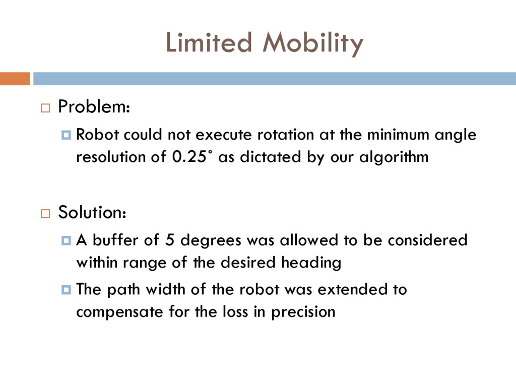
at the minimum angle resolution of 0.25˚ as dictated by our algorithm Solution: A buffer of 5 degrees was allowed to be considered within range of the desired heading The path width of the robot was extended to compensate for the loss in precision
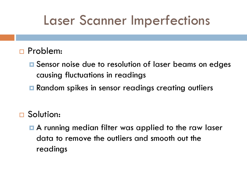
resolution of laser beams on edges causing fluctuations in readings Random spikes in sensor readings creating outliers Solution: A running median filter was applied to the raw laser data to remove the outliers and smooth out the readings
make it robust to uneven terrain of outdoor environments Implement a wireless kill switch to remotely disable the robot to make it safer for outdoor testing Configure the acceleration and deceleration of the robot for an outdoor environment
be used to distinguish between grass and non grass areas A full fledged coverage and mapping algorithm like 2D slam could be implemented on top of the obstacle avoidance algorithm to provide full coverage of a lawn