Upgrade to Pro — share decks privately, control downloads, hide ads and more …

Atmel Training Material on ASF and Arduino

OlegZero13
August 07, 2018

Atmel Training Material on ASF and Arduino

Training material created for Atmel, which shows how to use Atmel Software Framework 3 (ASF) for creating custom projects using Arduino.
It was a reverse-engineering work and a lot of fun. This material is publicly available at Microchip.

OlegZero13

August 07, 2018
Tweet

More Decks by OlegZero13

Other Decks in Technology

Transcript

  1. TRAINING MANUAL Customer application support in Atmel Studio Framework AN-9684

    Prerequisites  Hardware Prerequisites  SAMD21 Xplained Pro board  IO1 Xplained Pro extension board  OLED1 Xplained Pro extension board  Arduino Zero board  13 x male-to-male connector cable  USB micro cable  Software Prerequisites  Atmel Studio v. 6.2 or later  Atmel Studio Framework (ASF) v. 3.19 or later  Estimated Completion Time:  3-5 hours Introduction Atmel Studio Framework (ASF) has been written with the intention to support a wide range of Atmel’s microcontrollers and hardware boards by providing the customers with easy-to-use drivers and routines. However, in the process of writing firmware for a new hardware, one is very likely to encounter a situation, in which certain modifications are needed in order to support the features of the customer’s end product. Typically, these “customizations” could mean, for example: 1. Changing the user board layout, or porting the application code to a new microcontroller (MCU) 2. Adding support for a new hardware component. 3. Creating or altering a low-level driver in order to reach an accurate performance of a specific peripheral. 4. Creating or changing certain high-level software routines to provide more “tailored” options. Since the cases 3 and 4 require very user-specific needs, in this document, we are going to present a process of achieving the results in the first two situations. The processes will be shown based on SAM D21 family microcontrollers, although the approach presented in this training material is extendable to other MCUs. 9/15/2014
  2. The training material is composed of three assignments: In the

    first assignment, we are going to create of a simple sensing application, in which we are going to use one of Atmel’s evaluation kits (SAMD21 Xplained Pro board). We will try to keep the application code to a minimum. Instead, we will show how ASF is structured and explain how to quickly find and use relevant drivers thorough the example of a light sensing application. In the second assignment, we will discuss the necessary steps that one needs to follow to port an already existing application to a new board. For this purpose, we are going to use our project and modifying the relevant parts. Here, we are going to use Arduino Zero board to act as a custom hardware and use it instead of the original SAMD21 Xplained Pro board. In the third assignment, we will focus on creating the support for a custom hardware component. We will demonstrate this process using the OLED display as our component assuming that we do not have the support for it in Atmel Studio. Consequently, we will closely inspect the process of determining, which parts of ASF need to be customized, which have to be written anew and which should be left intact. Customer application support in ASF – Training Manual: 9/15/2014 Page 2 of 90
  3. Table of Contents Prerequisites......................................................................................1 Introduction.........................................................................................1 Icon Key Identifiers.............................................................................6 Training Module

    Architecture.............................................................7 1.1 Atmel Studio Extension (.vsix)............................................................7 1.2 Atmel Training Executable (.exe)........................................................7 Part 1. Basic ASF concept explained............................................8 1.1 Short introduction to ASF....................................................................8 1.1.2 Structure............................................................................................8 1.1.3 Folder structure.................................................................................9 Assignment 1 Building a small application.......................................11 1.2 General application concept..............................................................11 1.3 Connect the hardware.......................................................................12 1.4 Create a starting template for developing your application...............12 1.5 Redefine our input/output ports.........................................................15 1.6 Adding the drivers (RTC)...................................................................17 1.7 Configure the module (RTC).............................................................19 1.8 Configure the clock for the module (RTC).........................................20 1.9 Read the sensor input (ADC)............................................................21 1.10 Display the text (OLED)....................................................................24 1.11 Finalizing the application...................................................................25 1.12 Summary on Assignment 1...............................................................27 Part 2. Changing the board.........................................................28 2.1 Background information....................................................................28 Assignment 2 Creating a new board platform...............................32 2.2 Choosing the user board template....................................................33 2.3 Re-definition of new pinout................................................................33 2.4 Restoring the application environment..............................................35 2.5 Porting the application code..............................................................35 2.6 Cosmetic surgery..............................................................................38 2.7 Summary on Assignment 2...............................................................40 2.8 Preparing the project for Assignment 3.............................................40 Part 3 Adding support for a new component..............................42 3.1 Preliminary considerations................................................................43 Customer application support in ASF – Training Manual: 9/15/2014 Page 3 of 90
  4. 3.2 Understanding and creating the file structure....................................43 3.3 Connecting the

    files...........................................................................47 3.4 Bringing datasheet into the code.......................................................49 3.5 Creating low-level set of functions.....................................................52 3.5.1 Writing to the display controller........................................................52 3.5.2 Reading from the display controller.................................................54 3.5.3 Resetting of the display...................................................................54 3.5.4 Enabling and disabling the display..................................................55 3.5.5 Turning the display on and off.........................................................55 3.5.6 Setting contrast................................................................................56 3.5.7 Inverting the content........................................................................56 3.5.8 Addressing functions.......................................................................57 3.6 Initialization procedure......................................................................59 3.6.1 Internal initialization.........................................................................59 3.6.2 External initialization........................................................................60 3.7 High-level functions...........................................................................62 3.7.1 Access points: null-display, framebuffer and file structure…............63 3.7.2 Switching the points.........................................................................64 3.7.3 Tying two ends together..................................................................70 3.8 Summary on Assignment 3...............................................................72 Summary on ASF customization processes....................................73 Changing the board......................................................................................74 Adding support for a custom component......................................................75 Appendix A. Complete solution to Assignment 1.............................76 A.1 The body of the main.c file:....................................................................76 A.2 Changes to the conf_clocks.h file..........................................................79 Appendix B. Complete customized component files.......................79 B.1 The body of the oled_controller.h file:....................................................79 B.2 The body of the oled_controller.c file:....................................................81 B.3 The body of the conf_oled_controller.c file:............................................83 Appendix C. Complete customized service files..............................83 C.1 The body of the gfx_mono_null.h file.....................................................83 C.2 The body of the gfx_mono_null.c file.....................................................85 Appendix D. Taking advantage of ASF conventions and APIs........89 D.1 Peripheral module configuration............................................................89 D.2 The meaning of module instance and config struct’s.............................89 Customer application support in ASF – Training Manual: 9/15/2014 Page 4 of 90
  5. Icon Key Identifiers Delivers Contextual Information About a Specific Topic

    Highlights Useful Tips and Techniques Highlights Objectives to be Completed Highlights the Expected Result of an Assignment Step Indicates Important Information Highlights Actions to be Executed Out of the Target Customer application support in ASF – Training Manual: 9/15/2014 Page 6 of 90
  6. Training Module Architecture This training material can be retrieved through

    different Atmel deliveries:  As an Atmel Studio Extension (.vsix file) usually found on the Atmel Gallery web site (http://gallery.atmel.com/) or using the Atmel Studio Extension manager  As an Atmel Training Executable (.exe file) usually provided during Atmel Training sessions Depending on the delivery type, the different resources needed by this training material (hands-on documentation, datasheets, application notes, software & tools) will be found in different locations. 1.1 Atmel Studio Extension (.vsix) Once the extension is installed, you can open and create the different projects using “New Example Project from ASF..." in Atmel Studio. The projects installed from an extension are usually under “Atmel Training > Atmel Corp. Extension Name”. There are different projects which can be available depending on the extension:  Hands-on Documentation: contains the documentation as required resources  Hands-on Assignment: contains the initial project that may be required to start  Hands-on Solution: contains the final application which is a solution for this hands-on Each time a reference is made to some resources in the following pages, the user must refer to the Hands-on Documentation project folder. 1.2 Atmel Training Executable (.exe) Depending where the executable has been installed, you will find the following architecture which is composed by two main folders:  AN-XXXX_Hands-on: contains the initial project that may be required to start and a solution  Resources: contains required resources (datasheets, software & tools…) Unless a specific location is specified, each time a reference is made to some resources in the following pages, the user must refer to this Resources folder. Customer application support in ASF – Training Manual: 9/15/2014 Page 7 of 90
  7. Part 1. Basic ASF concept explained 1.3 Short introduction to

    ASF Atmel Studio Framework (ASF) provides a software interface library interface between Atmel MCU hardware registers and a user’s application code. With a strong focus on usability and portability, it has been organized in four layers, which provide support on different level of abstraction. Starting from the lowest-level, these are: boards, drivers, components and services. In addition to them, ASF provides useful application examples to help customers write their own applications. Figure 1.3.1.1.1. Atmel Software Framework structural layers. 1.1.1 Structure According to the specification ASF, each of these layers is dedicated to supporting our application at a specific level. Knowing of these layers is a key to customize our application project. Let us quickly summarize their purpose: Boards: This layer contains the basic definitions of pinout, as well as initialization of the board (e.g. bringing all I/O ports to a preset configuration). One may think of this layer as a reflection of the board schematic in the software. We will mostly deal with that layer in Assignment 2. Drivers: This layer consists of low-level software routines that are used to handle MCU peripherals, such as the Serial Parallel Interface (SPI), Analog-to-Digital Converter (ADC), Universal Serial Bus (USB), etc. Drivers constitute a fundamental “bridge” between the register- level description and software routines. These APIs provide a more user-friendly interface to the peripheral configuration, comparing to the register-level code. Components: This layer is, in a way, very similar to drivers. However, its intention is to provide a set of routines targeted to handle components that are external to the MCU, such as displays, memories, sensors, transceivers, etc. Since such components usually require some configuration (e.g. configuring their own registers), they often use drivers and for this reason they are placed directly above them. Customer application support in ASF – Training Manual: 9/15/2014 Page 8 of 90
  8. Services: This is a high-level layer, which contains pre-made software

    functions designed to facilitate application-level code. Typical examples could be:  GFX Monochrome library that contains parameterized graphical figures to be displayed,  USB Host to optimize the USB functionality for some devices,  FAT file system to facilitate handling of the file formats, etc. They are placed above all mentioned layers, as they are the least hardware-specific entities. In addition to the four layers that will be the main scope of this training, ASF structure also distinguishes the following: Utilities: They are represented as the gray vertical layer. This layer contains all the compiler abstraction files, which allow using different compilers (currently GCC and IAR). Utilities unify differences in e.g. interrupt handling routines, which might exist between these compilers, as well as definitions of specific types that are characteristic to embedded programming (e.g. uint8_t denoting an 8-bit unsigned integer). Utilities are outside the scope of this training. Applications: This is a bank of few thousands of example applications projects intended to help customers develop their own application. Your code: This layer represents customer application code. 1.3.2 Folder structure ASF predicts a specific folder structure, which reflects the four layers we have just discussed. First of all, all project input files are located under ../src/, wherein we can find the main.c file, asf.h header file and two folders: ASF and config.  The main.c file is the main application code.  ASF.h file is a primary “binder” of our project. It contains #include statements that collect all relevant libraries that are used in our project.  The config folder is where we will find static header files that are related to specific drivers and used for configuring them. (We will use it very often later).  Finally ASF folder that contains all the discussed four layers. The code related to the four-layer (inside ASF folder) is organized through the following subfolders:  common – contains the portion of ASF that is absolutely common to all Atmel MCUs and boards.  sam0 – contains the portion of ASF that is specific to the SAM-cortex M0 devices, such as SAMD21. In case, we select a project based on XMEGA Customer application support in ASF – Training Manual: 9/15/2014 Page 9 of 90
  9. family, this folder would be replaced by xmega. Similarly with

    the AVR, 32-bit AVR or tiny.  common2 – is essentially an exception to the rule, since it contains files that are common only to a subgroup of MCUs. At the same time, the content of this folder is not exclusive to SAM0 devices.  thirdparty – is a place of all “non-Atmel” libraries, as well as Atmel-related libraries that do not share the same license as standard ASF libraries. Finally, if we inspect the content of the common, common2 and sam0 folders, we will find out that these folders contain one or more of the following subfolders: boards, drivers, components, services and utils. As you probably expect, these folders will contain the necessary ASF code used by our application at each of the four levels. asf.h file is being generated by ASF Wizard automatically. It is being modified every time a user executes changes to the selected ASF modules. Because the ASF Wizard ensures that all modules’ dependencies are respected, users are, therefore, strongly discouraged from editing this file. Having been equipped with this knowledge, we are ready to move to the first assignment.  Customer application support in ASF – Training Manual: 9/15/2014 Page 10 of 90
  10. Assignment 1 Building a small application 1.4 General application concept

    During this exercise, we are going to create a simple application for ambient light sensing, featuring SAMD21 MCU, a light sensor and OLED display. We will be using SAMD21 Xplained Pro board as a basic platform and all necessary drivers we will find in Atmel Studio. The following diagram presents the software concept of our application: Figure 1.4.1.1.1. Concept of the application featuring ADC and OLED. The phototransistor is available on IO1 Xplained Pro board. We will use the ADC to read the input voltage that is a function of the light intensity. In the main loop of the application program, we will calculate the ambient light level based on the ADC’s input and transform it into text form. In the end, the text will be sent to the small display (available on OLED1 Xplained Pro board) with a frequency dictated by the Real Time Clock (RTC). Customer application support in ASF – Training Manual: 9/15/2014 Page 11 of 90
  11. 1.5 Connect the hardware Connect the extension wings: IO1 Xplained

    Pro board to EXT1 socket on SAMD21 Xplained Pro. Similarly, connect OLED1 Xplained Pro to the EXT3 on SAMD21 Xplained Pro board. Use the USB cable to connect it to your PC. Figure 1.5.1.1.1. Connecting SAMD21 Xplained Pro and OLED1 and IO1 Xplained Pro wings for Assignment 1. 1.6 Create a starting template for developing your application Since we are working with the Atmel boards, the most efficient approach for developing our application would be let Atmel Studio create a predefined template for our boards. By doing this, we let Atmel Studio to configure the board definitions automatically letting us, therefore, to begin directly with the application code. Open Atmel Studio 6.2 and create the “correct” template.  Go to File > New > Project…  Select the GCC C ASF Board Project template  Name it Application1  Choose a path on your disk.  Press OK. Customer application support in ASF – Training Manual: 9/15/2014 Page 12 of 90
  12. It is highly recommended that the specified path be short.

    Figure 1.6.1.1.1. Choosing the correct template. The MCU available on the SAMD21 Xplained Pro board is SAMD21J18A. You may use the search window and type it directly to quickly select the device. Here, we choose the GCC C ASF Board Project as it offers us the most comfortable interface for choosing both the MCU and the board. You have two possibilities to select the board.  Select the SAMD21 Xplained Pro.  Press OK. Customer application support in ASF – Training Manual: 9/15/2014 Page 13 of 90
  13. Figure 1.6.1.1.2. Choosing the correct MCU and board wizard. We

    have now created a template for working directly on our application. The template follows with a simple auto-generated code for blinking an LED. To check and see if it works, you will need to:  Build the project by going to Build > Build Solution, pressing button or simply pressing F7.  After the project have compiled, you will need to upload it to the MCU. Go to Debug > Start Without Debugging or press button.  Unless you have specified the tool before, Atmel Studio will ask you to select it. Select the EDBG (Embedded Debugger) Customer application support in ASF – Training Manual: 9/15/2014 Page 14 of 90
  14. Figure 1.6.1.1.3. Choosing the programming interface.  It may also

    happen that Atmel Studio will ask you to upload a new firmware to the device. Do it and wait until it finishes, then perform the routine one more time. The MCU is uploaded a new firmware now. You can press the button and flash the LED. 1.7 Redefine our input/output ports During developing of an application it is often convenient to have a possibility of using LEDs and buttons to check if a given feature of the code works. Let us, therefore, begin with this step. Enable LED1 and LED3 on OLED1 Xplained Pro. In addition, let the LED1 be activated by pressing the Button1. In order to function, the pins that are connected to the LEDs need to be configured as output. Conversely, we need to configure the pin connected to the button(s) as input. Furthermore, if we looked at the schematic, we would see that the using of the button requires enabling the internal pull-up option. Write a function port_init() that configures the pins accordingly. Place the prototype in the main.c function before the main function. void port_init(void) { struct port_config pin_conf; port_get_config_defaults(&pin_conf); /* Configure LEDs as outputs, turn them off */ pin_conf.direction = PORT_PIN_DIR_OUTPUT; port_pin_set_config(LED1, &pin_conf); port_pin_set_config(LED3, &pin_conf); /* Set buttons as inputs */ pin_conf.direction = PORT_PIN_DIR_INPUT; pin_conf.input_pull = PORT_PIN_PULL_UP; port_pin_set_config(BUTTON, &pin_conf); } Customer application support in ASF – Training Manual: 9/15/2014 Page 15 of 90
  15. The port_init() was, in fact, created following a standard procedure

    of configuring a peripheral that applies to all devices of the SAM0 family. This is a five step process: 1. Define a configuration structure. We create a struct of a specific type dictated by a peripheral, which will store the configuration settings for a given peripheral module. 2. Load with defaults. We use xxx_get_config_defaults function to set all the predefined values. This makes the configuration easier, as we will only need to focus on specific parts that are relevant for us. 3. Modify the configuration. Depending on the application requirements, we change only the specific values 4. Initialize. We load the modified data to the structure using. 5. Enable. Finally, we set the flag to enable the peripheral. (Sometimes steps 4 and 5 can be combined.) Next, we need to define what LED1, LED3 and BUTTON are. Consequently, let us add the definitions (place them at the beginning of the main.c file). #define LED1 EXT3_PIN_7 #define LED3 EXT3_PIN_6 #define BUTTON EXT3_PIN_9 You might have noticed that once we have added these definitions, the color of the names change from black to purple everywhere inside the project. This is a sign that Atmel Studio “recognizes” these names. This small feature will prove useful in the later parts of this training. In order to enforce the port configuration, we must call the port_init function in the actual code. We do that before the “while” loop – the so-called program loop. port_init(); Finally, let us modify the content of the program loop, such that it constantly checks for the state of the button and adjusts the LED1 state accordingly: while (1) { // Is button pressed? if (port_pin_get_input_level(BUTTON)) { // Yes, so turn LED on. port_pin_set_output_level(LED1, true); } else { // No, so turn LED off. port_pin_set_output_level(LED1, false); } } Now, we should be able to use LED(s) and BUTTON(s) anytime to verify our application. (You may run the code to check if it works correctly. 1.8 Adding the drivers (RTC) Having created a template for our application, the next step is to select the drivers (services and components) that are needed for our application. Let us reflect on our concept of application. In this application we will need to select: Customer application support in ASF – Training Manual: 9/15/2014 Page 16 of 90
  16.  Analog-to-Digital Converter (ADC) driver – for measuring the sensor

    level  Real Time Clock (RTC) driver – for simple timing management  GFX Monochrome Font service – to be able to output text on the OLED In order to include the new drivers we will be using ASF Wizard feature of Atmel Studio. Note that it is not necessary to select all drivers at this point. The drivers can be freely added and removed anytime during developing the project. We will, however, go step-by-step in order to accurately monitor the processes. We will start with the RTC driver, which is integrated in ASF. The RTC driver is not obligatory, but it will give us some control over timing for executing the events by our code. Add the RTC driver Press button (also available under ASF > ASF Wizard). Figure 1.8.1.1.1. ASF Wizard window Customer application support in ASF – Training Manual: 9/15/2014 Page 17 of 90
  17. The window that appears is ASF Wizard. We will use

    this window anytime we need to add or remove the drivers. Observe that some drivers are already included in our project by default. An example is the PORT driver that contains all functions, macros and definitions used to configure ports and pins in various ways. Remember, we have used some of these functions in the last step. Naturally, the reason the project compiled (and the functions were displayed as red) was that we had this driver already included. Select the RTC driver in the count_callback mode and Add it to the selected modules and Apply the changes. We opt for the callback option as it will provide us with an application interface, which will allow us to act when the counter overflows (we will see that later). In general, ASF Wizard offers us two possibilities of APIs: callbacks and polled. Callback versions make module operating interrupt-driven offering a user to define a function that will be executed upon a certain event (e.g. timer overflow, receiving data through USART, etc.). Polled versions are the opposite – no interrupt will be executed and it is user’s responsibility to check a particular flag. Therefore, polled versions are predominantly used if we want to simplify the code and do not need to define any interrupt-related action. Now let us give a little bit of attention to the pop-up window that just appeared. Figure 1.8.1.1.2. Summary of operations when selecting/deselecting ASF modules. By selecting and adding the RTC driver, we ask the Atmel Studio to include the all files that are relevant to manage the RTC module. Recalling ASF folder structure, observe that a new folder has been added to the following path: ../src/ASF/sam0/drivers path. It is placed inside sam0 folder, suggesting that the files added are exclusive for SAM0 device family. In addition, a compiler symbol ‘RTC_COUNT_ASYNC=true’ has been defined. When looking into the driver files, we can see that they are often written to support more than one configuration, using conditional statements such as #ifdef. In case of the RTC, we have four: count-polled, count- Customer application support in ASF – Training Manual: 9/15/2014 Page 18 of 90
  18. callback, calendar-polled and calendar-callback. The flag is then used to

    “choose” the specific one. Press OK and expand ASF Explorer window to the right now. Figure 1.8.1.1.3. ASF Explorer Here, you will see the summary of all ASF features (drivers, components, services) that are added to the project, together with their dependencies. Most importantly, if you expand the node, you will see a link to ASF documentation that discusses each module together with a Quick Start Guide that provides a straightforward recipe of setting up any module. The RTC driver has been added. You also learnt where to find the documentation and help for building your own projects. 1.9 Configure the module (RTC) After we have added the support for the RTC module, we need to configure it and enable it in the software. We will follow a very similar process to configuring the port. Let’s create the following code and place it in the main.c file, before the main function. struct rtc_module rtc_instance; void configure_rtc_count(void) { struct rtc_count_config config_rtc_count; rtc_count_get_config_defaults(&config_rtc_count); config_rtc_count.prescaler = RTC_COUNT_PRESCALER_DIV_1; config_rtc_count.mode = RTC_COUNT_MODE_16BIT; config_rtc_count.continuously_update = true; rtc_count_init(&rtc_instance, RTC, &config_rtc_count); rtc_count_enable(&rtc_instance); } void rtc_overflow_callback(void) { /* Do something on RTC overflow here */ port_pin_toggle_output_level(LED3); } Customer application support in ASF – Training Manual: 9/15/2014 Page 19 of 90
  19. void configure_rtc_callbacks(void) { rtc_count_set_period(&rtc_instance, 128); rtc_count_set_count(&rtc_instance, 0); rtc_count_register_callback( &rtc_instance, rtc_overflow_callback,

    RTC_COUNT_CALLBACK_OVERFLOW); rtc_count_enable_callback(&rtc_instance, RTC_COUNT_CALLBACK_OVERFLOW); } This code configures the Real Time Clock to operate in 16 bit mode with no pre-scaling of the input clock. In addition to that, it initializes and enables the callback function that will be associated with the counter overflow. By setting the period to 128 and count to 0, we will get the rtc_overflow_callback() function execute 4 times a second, if we provide the a 32 kHz clock source to the module. Check the API Documentation and the Quick Start Guide for more options. In the body of the main function (and before the while loop), execute the two initializations: /* Configure and enable RTC */ configure_rtc_count(); /* Configure and enable callback */ configure_rtc_callbacks(); The RTC is now almost ready to work. We have defined all software functions, configured the module and enabled it. The only thing that we still miss is providing it with the correct input clock signal. 1.10 Configure the clock for the module (RTC) In most cases, one will not need to change the clock settings during MCU’s operation. Therefore, ASF provides a convenient way of pre-configuring the clock setting using a separate file. Configure the input clock for the RTC module. Inspect the ../src/config folder and open the conf_clocks.h file. If you need to return to the Solution Explorer, but you have accidentally closed the window, you can open it again in View > Solution Explorer. In the conf_clocks.h file, you will find many options that are available for the clock configurations. The selection process is based simply on changing the #define flags. To keep the promise of executing the rtc_callback_overflow() every quarter of a second, we need to enable the internal 32 kHz clock. In addition, we need to assign it to the General Clock (GCLK) #2, which is intended to function as the RTC. In general, we are not hardware-limited to used GCLK2 for the RTC module. However, GCLK2 is unique in a way, that it is the only clock generator that has only 5 division factor bits. Being in this way reduced, using of GCLK2 is a step to minimize the power consumption. Customer application support in ASF – Training Manual: 9/15/2014 Page 20 of 90
  20. Find the relevant blocks of code and replace them with

    the following settings: /* SYSTEM_CLOCK_SOURCE_OSC32K configuration - Internal 32KHz oscillator */ # define CONF_CLOCK_OSC32K_ENABLE true # define CONF_CLOCK_OSC32K_STARTUP_TIME SYSTEM_OSC32K_STARTUP_130 # define CONF_CLOCK_OSC32K_ENABLE_1KHZ_OUTPUT true # define CONF_CLOCK_OSC32K_ENABLE_32KHZ_OUTPUT true # define CONF_CLOCK_OSC32K_ON_DEMAND true # define CONF_CLOCK_OSC32K_RUN_IN_STANDBY false /* Configure GCLK generator 2 (RTC) */ # define CONF_CLOCK_GCLK_2_ENABLE true # define CONF_CLOCK_GCLK_2_RUN_IN_STANDBY false # define CONF_CLOCK_GCLK_2_CLOCK_SOURCE SYSTEM_CLOCK_SOURCE_OSC32K # define CONF_CLOCK_GCLK_2_PRESCALER 32 # define CONF_CLOCK_GCLK_2_OUTPUT_ENABLE false Some flags just need a true or false input, whereas some offer more options. If you wish to investigate further, mark e.g. SYSTEM_OSC32K_STARTUP_130 and press Alt + G. This will bring you to the original definition. The clock is configured as desired – we assign 32 kHz internal oscillator to GCLK2, which we later pre-scale with a factor of 32, thus obtaining a 1 kHz clock. Using the count_set_period; function with a 1024 value would result in RTC overflowing exactly once a second. Setting it to a quarter of this value makes this occurrence 4 times more frequent. You may want to verify your result. Try inserting port_pin_toggle_output_level(LED3); inside the rtc_callback_overflow() function. In this case, start without debugging (by clicking button). 1.11 Read the sensor input (ADC) For now our application is only blinking an LED. Let us move to the new step, which will involve reading the state of the light sensor. As discussed in the general concept, this part will require us to use the Analog-to- Digital Converter. Although it is a different peripheral module, we are going to follow a very similar procedure. All we need is to:  Add the ADC driver through ASF Wizard  Configure the clock source for the module  Create a configuration function, in which we will:  Create a struct for ADC configuration  Load the default values  Adjust the parameters according to our application’s needs  Assign these changes to the peripheral  (optionally) register a callback  Create a callback – define what it should do  Enable the module  In this case – initialize the first ADC conversion  Finally, do something with the ADC results in the application code Customer application support in ASF – Training Manual: 9/15/2014 Page 21 of 90
  21. Using the ASF Wizard, add the ADC driver to our

    application. In the configuration settings, choose the callback version. The ADC driver is added to the project. If we check the “../src/ASF/sam0/drivers/”, we should see that the ADC folder containing libraries is included. Enable the Generic Clock #3, which we will use for the ADC module. Let the internal 8 MHz oscillator remain the input source for the clock. In conf_clocks.h replace the relevant block of the code with the following: /* Configure GCLK generator 3 */ # define CONF_CLOCK_GCLK_3_ENABLE true # define CONF_CLOCK_GCLK_3_RUN_IN_STANDBY false # define CONF_CLOCK_GCLK_3_CLOCK_SOURCE SYSTEM_CLOCK_SOURCE_OSC8M # define CONF_CLOCK_GCLK_3_PRESCALER 30 # define CONF_CLOCK_GCLK_3_OUTPUT_ENABLE false The GCLK 3 is now enabled and ready to be used. Configure and initialize the ADC with the following parameters:  Gain factor: 2  Clock prescaler: 512  Reference: input VCC1  Positive PIN: PIN #8  Resolution: 12-bit The light intensity is acquired by using of a phototransistor (datasheet), whose collector-emitter current is proportional to the light intensity illuminating of transistor’s base. Since the transistor is connected as pull-down, the voltage measured by the ADC becomes inversely proportional to the light intensity. A simple way of correcting for this is to subtract the measured value from the top value of the ADC output, which is 0xFFF for 12-bit configuration. Given that the voltage we measure can swing from GND to VCC, we will use the internal VCC divided by 2. Note that it is not the only “correct” way to configure of the ADC. However, it suffices for our application. Create the light_sensor_init()function, which we will use for configuring of the ADC. Use the following code:  Declare the following global variables and constants: struct adc_module adc_instance; #define ADC_SAMPLES 1 uint16_t adc_result_buffer[ADC_SAMPLES]; volatile bool adc_read_done = false; Here, we define the global structure for holding the ADC configuration. Next, we define the number of samples that we want to receive upon each ADC conversion. As mentioned before, we are going to focus on customization process rather than the application itself; hence one sample is perfectly enough. According to ASF documentation, the ADC writes its measurement to a buffer. This is why define a table in the third line of this code. Finally, we need a software Customer application support in ASF – Training Manual: 9/15/2014 Page 22 of 90
  22. flag to signalize when the ADC conversion is finished. It

    is signified as volatile since this variable is going to be accessed from different parts of the program.  Create the initialization function (before the main function in the main.c file): void light_sensor_init(void) { struct adc_config config_adc; adc_get_config_defaults(&config_adc); config_adc.gain_factor= ADC_GAIN_FACTOR_DIV2; config_adc.clock_prescaler = ADC_CLOCK_PRESCALER_DIV512; config_adc.reference = ADC_REFERENCE_INTVCC1; config_adc.positive_input = ADC_POSITIVE_INPUT_PIN8; config_adc.resolution = ADC_RESOLUTION_12BIT; adc_init(&adc_instance, ADC, &config_adc); adc_enable(&adc_instance); adc_register_callback(&adc_instance, adc_complete_callback, ADC_CALLBACK_READ_BUFFER); adc_enable_callback(&adc_instance, ADC_CALLBACK_READ_BUFFER); } This implementation is following the general procedure of loading the default configuration, changing the necessary parameters, initializing and enabling the module and registering a callback.  Finally, call the light_sensor_init() in the main function, before the while loop. Configure the callback function. Place the following code, before the main function. void adc_complete_callback(const struct adc_module *const module) { adc_read_buffer_job(&adc_instance, adc_result_buffer, ADC_SAMPLES); adc_read_done = true; } The way our program is going to work with the ADC is to call for this callback function every time it completed a new conversion. In this function, we ask the ADC to perform a new conversion, which will keep the ADC working in the background at all times. Last, but not least, we need to “manually” trigger the first conversion. Otherwise, the ADC will be ready to work, but always waiting for the first call to start “the chain reaction”. Place the following code just before the main loop in the main.c file, but after light_sensor_init(). system_interrupt_enable_global(); adc_read_buffer_job(&adc_instance, adc_result_buffer, ADC_SAMPLES); while (adc_read_done == false) { /* wait for asynchronous adc read to complete */ } Customer application support in ASF – Training Manual: 9/15/2014 Page 23 of 90
  23. The ADC part is operational now. Our application reads the

    sensor data. Configuring of ADC follows a certain procedure that is also applicable to other peripheral modules. Watching more carefully, we could see that in case of ADC example, two structures have been defined:  struct adc_module adc_instance;  struct adc_config config_adc; They both serve different purpose and so they should not be confused. The first one – adc_instance –serves as a hardware module representation in the software. It contains for example sampled data in a buffer or information about the status of it. The second one – config_adc – is used only to configure and initialize the module. In most cases, the first one should be declared as global, while in the second case it can be declared as local or global depending on the application. More information concerning the ASF code optimization is available in Appendix D. 1.12 Display the text (OLED) Finally, we have reached the last part of our program. In this part we are going to add and configure the GFX Monochrome – System Font, which is a service – ASF’s highest layer. The way we implement its features in the project is again going to follow the standard process. However, in order to prepare us for the later exercises, we are going to give it a little bit more attention. Add the OLED functionality and display the messages about the ambient light level. Use the ASF Wizard and add the GFX Monochrome – System Font service to our project. Select the ug_2832hsweg04 for the display driver and polled version of the SERCOM SPI driver. In order to change these options, you must have expanded ASF feature “tree” in the Selected Modules window. Let’s spend a moment and observe the dependencies. Figure 1.12.1.1.1. View of peripheral modules supported by the application. Customer application support in ASF – Training Manual: 9/15/2014 Page 24 of 90
  24. The GFX Monochrome – System Font (service) incorporates two blocks:

    the Monochrome Graphic Library (service) and the Graphical Primitives (pixel, line, square, and circle) (service). The first one relies upon another service, which in our case is called Display Driver (service): ug_2832hsweg04. By selecting this one, instead of the default null driver, ASF Wizard includes the underlying component layer, which is the SSD1306 OLED controller. This is a physical device that is used to drive the OLED screen that we use. The component layer therefore “translates” all the high-level routines to a language that is suitable for this very display. Finally, the choice of the SSD1306 OLED controller involves ensuring that even lower-level MCU module related drivers are also included in the project. You have probably noticed that the PORT and SYSTEM had already been added before. This is true, but they are not being added twice. We will later see how they are exactly implemented without causing a conflict. At this step, however, it is useful to remember, which of the low-level drivers are needed to support our particular component and ASF. Initialize the OLED by placing the following code before the while loop in the main.c file. gfx_mono_init(); The OLED is now enabled and ready. In fact, we did not need to spend much time configuring it, because the largest part is essentially performed automatically through ASF Wizard. 1.13 Finalizing the application So far we have added, configured and enabled all three modules that we need in our project. However, we still need to complete the application code. As mentioned in the introduction, we do not want to spend much time on the application. If you wish to learn how to create a similar application with more optimal allocation of resources and robustness, we recommend to you this training. What our application needs to do is to convert the raw data stored in the adc_result_buffer to a readable format and display this information on the screen. We need to create the remaining part of the code. Declare the global variables and constants in the main.c file. #include <stdio.h> char disp_string[10]; #define APP_STR_LENGTH 16 volatile bool oled_refresh_ready = false; uint16_t brightness = 0; #define UPPER_BOUND 4000 #define LOWER_BOUND 200 The first line of the code includes the stdio.h library, which we will need to support creating the string of text. Create a function display_result(), with the following piece of code: void display_result(void) { brightness = 4096 - adc_result_buffer[0]; if (brightness < LOWER_BOUND) { gfx_mono_draw_string("Min", 76, 0, &sysfont); Customer application support in ASF – Training Manual: 9/15/2014 Page 25 of 90
  25. } if (brightness > UPPER_BOUND) { gfx_mono_draw_string("Max", 76, 0, &sysfont);

    } if ((brightness >= LOWER_BOUND) && (brightness <= UPPER_BOUND)) { snprintf(disp_string, APP_STR_LENGTH, "%4d%%", (brightness*100 - LOWER_BOUND*100)/(UPPER_BOUND - LOWER_BOUND)); gfx_mono_draw_string(disp_string, 64, 0, &sysfont); } } The first line in this function inverts the result of the readout, meaning that the highest value of our variable – brightness will correspond to the highest light intensity. In the later lines, we recalculate the raw ADC readout into percents. We also use the MIN-MAX values for convenience. Finally the gfx_mono_draw_string() function is use to display the text on the OLED. As arguments, it accepts a string of characters to display, the x- and y- coordinates counted from the top-left corner of the display and expressed in pixels and a pointer to a set of predefined font glyphs. Initialize the display routine. Place the following code just before the main loop. gfx_mono_init(); oled_refresh_ready = true; gfx_mono_draw_string("Brightness:", 0, 0, &sysfont); Implement the call to display_resut() in the while loop of the program. Use the following code (in addition the LED blinking code). if (oled_refresh_ready) { oled_refresh_ready = false; display_result(); } Finally, add one more line into the RTC callback function, which will make the OLED be refreshed 4 times a second. oled_refresh_ready = true; Our application is now ready. Build the project and upload it to the MCU. The complete code for this exercise is available in the Appendix A. Save the project. 1.14 Summary on Assignment 1 Apart from creating a light sensing application, we have leant few very important things here. Let us summarize: Customer application support in ASF – Training Manual: 9/15/2014 Page 26 of 90
  26. ASF discriminates four layers; counting from the bottom, these are:

    boards, drivers, components and services. Each of the layers is responsible for fulfilling different tasks. The folder structure of ASF distinguishes between features, whether they are shared by several MCUs. The subfolders reflect the four-layers just mentioned. In addition to ASF folder, all configurations that are meant to be static are placed in xyz_conf.h files under ../config/ folder. ASF Wizard is used to add and remove different ASF support features as well as to illustrate the dependencies. ASF Wizard provides a direct link into the documentation of each module. Preparing most of the modules follows a very similar procedure (valid only for SAM series). Equipped with this knowledge, we are ready to move to Assignment 2. Part 2. Changing the board 2.1 Background information During this part, we are going to port our application to a new “custom” board. Here, we will use Arduino Zero in combination with the two extension boards: IO1 and OLED1 Xplained Pro to emulate a custom hardware. The approach presented here is general and extendable to a large number of MCUs. As an example for this exercise, we choose the Arduino as it has a large community of makers worldwide; therefore we will also show how to include Arduino into ASF ecosystem. Figure 2-1 presents a general process of transferring an application to a new board. Customer application support in ASF – Training Manual: 9/15/2014 Page 27 of 90
  27. Figure 2.1.1.1.1. The process of porting an application to a

    new board using ASF. Before we start, we will need to “create” our hardware by connecting the right pins. Since Arduino Zero is based on SAMD21G18A version of the MCU, whereas the SAMD21 Xplained Pro kit uses SAMD21J18A the numbers of pins in both devices are different. In principle, designing a new hardware is a task in itself. Naturally, that would require us to analyze the datasheet(s) to inspect the pins’ functionality, as well as the electrical schematics for all boards: SAMD21, OLED1, IO1 Xplained Pro and Arduino Zero*. As you know from Assignment 1, our application needs an ADC pin, SERCOM SPI pins and GPIOs. As long as we find a way to exploit these functionalities with a new MCU, our choice of the exact pins that we use is somewhat arbitrary. In order to save time, let us therefore agree on proposed configurations. Table A-1 and A-2 summarize the relevant pin-to-peripheral connections used in the Assignment 1. OLED1 Xplained Pro SAMD21 Xplained Pro OLED pins nam es board names J10 0 EXT 3 - names pin function Customer application support in ASF – Training Manual: 9/15/2014 Page 28 of 90
  28. 12 SDIN SPI_MOSI 16 PB22_S5_SPI_M OSI PB22 SERCOM 5 -

    PAD[2] 11 SCLK SPI_SCK 18 PB23_S5_SPI_S CK PB23 SERCOM 5 - PAD[3] 10 D/C# DATA_CMD_S EL 5 PB30_GPIO_LE D PB30 SERCOM 5 - PAD[0] / (GPIO) 9 RES # DISPLAY_RES ET 10 PA27_GPIO_SS PA27 GPIO 8 CS# DISPLAY_SS 15 PB17_S5_SPI_S S PB17 SERCOM 5 - PAD[1] LED1 7 PA12_PWM_TC2 _0 PA12 GPIO LED3 6 PA15_GPIO_BT N PA15 GPIO BUTTON1 9 PA28_GPIO_IRQ 8 PA28 GPIO IO1 Xplained Pro SAMD21 Xplained Pro Light Sen. name J10 0 EXT 1 - name pin function 1 LIGHTSENSOR 3 PB00_ADC8 PB00 ADC[8] Table A.1.1.1.1.1.Summary of pin connection between SAMD21 Xplained Pro board and extension wings. OLED1 Xplained Pro Arduino Zero our custom name board J100 ext . pin function DISP_SS DISPLAY_SS 15 D1 3 PA17 SERCOM 1 - PAD[1] DISP_SCK SPI_SCK 18 D1 2 PA19 SERCOM 1 - PAD[3] DISP_MOSI SPI_MOSI 16 D1 0 PA18 SERCOM 1 - PAD[2] DISP_RES DISPLAY_RES ET 10 D9 PA07 GPIO DISP_CMD DATA_CMD_S EL 5 D8 PA06 SERCOM 1 - PAD[0] /GPIO LED1 7 D0 PA10 GPIO LED3 6 D1 PA11 GPIO BUTTON1 9 D4 PA14 GPIO IO1 Xplained Pro Arduino Zero name J100 ext . pin function LIGHTSENSOR 3 A0 PA02 ADC[0] Table A.1.1.1.1.2.Summary of pin connections between Arduino Zero board and extension wings. As you can see, the display uses a set of five pins: 3 x SERCOM SPI pins and 2 x GPIO. Due to the pin arrangement change between the devices, we are forced to change the SERCOM module from #5 to #1. Similarly, we change the ADC input from #8 to #0. Customer application support in ASF – Training Manual: 9/15/2014 Page 29 of 90
  29. Assemble our hardware by connecting the ports as shown in

    the pictures below. Great care must be taken by performing this step. Do not connect it to power before you have finished. Take special precautions when connecting VCC and GND. Reversing polarity will result in damaging of the hardware. Figure 2.1.1.1.2. Visual representation of all connections that have to be made for our custom hardware. It does not matter, whether any of the boards is connected to the 5V or 3.3V as they are both equipped with a power regulator. Our “custom” hardware is now created. Assignment 2 Creating a new board platform We are ready to look back into the code again. Having decided on the new pinout, all we need to do is to redefine each and every connection in the software. In fact, with help of ASF, it is possible to work with the bottom layer (boards) without changing anything in the remaining ones. With the changing of the board, we are going to work primarily with four files: Customer application support in ASF – Training Manual: 9/15/2014 Page 30 of 90
  30.  board.h stored in ../src/ASF/common/boards/  user_board.h stored in ../src/ASF/sam0/boards/

     init.c stored in ../src/ASF/sam0/boards/  conf_board.h stored in ../src/config/ Each of these files has a specific purpose. board.h This file acts as a selector. It contains the list of all boards and extensions supported by Atmel. Based on the choice we make when deciding to use the right template, this file is used to select the correct pre-settings for each case. Choosing SAMD21 Xplained Pro, for example, results in adding: ../src/ASF/sam0/boards/samd21_xplained_pro/samd21_xplained_pro.h. Importantly, one of the possible choices is a user board. user_board.h This is the definition of all board’s pinout. It translates the MCU’s pins (e.g. PA21) to whatever is connected to them (e.g. ADC[7] or SPI_MISO) thus separates the abstraction layer and makes our application development easier and more robust. init.c This file is used for I/O pin configuration. It is a place for initialization of all pins that is required by components connected to them. conf_board.h We might face a situation, in which our intention is to create a prototyping board (similar to Arduino!), in which some connectors are intentionally left open with a possibility to be connected to different peripherals. In such situation, it would be practical to define special logical flags that can be used to indicate, whether a given peripheral is connected or not. For example: in our application, we have decided to connect OLED to a group of pins. However, although we pretend it is hard-wired to our MCU, we may want to replace it with some other component in the future. In such cases, a set of flags could in principle prevent us from possible errors resulting from using conflicting names. Before we start a new project, have a look at how these four files look when using SAMD21 Xplained Pro board. See how they look. 2.2 Choosing the user board template We need to open a new template that is relevant for our new board. Open a new project in Atmel Studio just like you did before. Add it to the existing solution. Name it as: Application2. Choose SAMD21G18A as a microcontroller and select user board in the menu. This time have a template for SAMD21G18A and a user board. By generating this template, we have actually enforced a new definition in board.h file. Customer application support in ASF – Training Manual: 9/15/2014 Page 31 of 90
  31. Right-click on the Application2 project and choose the option: Set

    as StartUp project. Application2 becomes the default project when compiling and uploading. 2.3 Re-definition of new pinout What we have now is an empty template, in which we have to fill out the blank files. Create a new pin definition in ..src/ASF/common2/boards/user_board.h file. Open the user_board.h. Look at the Arduino Zero schematic file and define the connections between SAMD21 pins and Arduino Zero connectors. Place the following code in this file before the #endif statement. /* Arduino Zero header definitions */ #define SCL PIN_PA23 #define SDA PIN_PA22 #define AREF PIN_PA03 #define D13 PIN_PA17 #define D12 PIN_PA19 #define D11 PIN_PA16 #define D10 PIN_PA18 #define D9 PIN_PA07 #define D8 PIN_PA06 #define D7 PIN_PA21 #define D6 PIN_PA20 #define D5 PIN_PA15 #define D4 PIN_PA14 #define D3 PIN_PA09 #define D2 PIN_PA08 #define D1 PIN_PA11 #define D0 PIN_PA10 #define A5 PIN_PB02 #define A4 PIN_PA05 #define A3 PIN_PA04 #define A2 PIN_PB09 #define A1 PIN_PB08 #define A0 PIN_PA02 We have established the correspondence between the MCU’s physical pins and Arduino Zero connectors. Open ../src/config/conf_board.h file and define two flags. Note that this step is optional, as we are not going to replace any of the components used in our project. However, we are presenting it here just to show ASF best practice. #define OLED_PRESENT true #define LIGHT_SENSOR_PRESENT true Customer application support in ASF – Training Manual: 9/15/2014 Page 32 of 90
  32. Return to user_board.h file and add the definitions describing the

    connection between the Arduino Zero connectors and the peripherals: OLED and the light sensor, just as indicated in tables A-1. and A-2. Place the following code after the previous block. /* I/O pins */ #define LED1 D0 #define LED3 D1 #define BUTTON D4 /* OLED connections */ #ifdef OLED_PRESENT #define DISP_SS D13 #define DISP_SCK D12 #define DISP_MOSI D10 #define DISP_RES D9 #define DISP_CMD D8 #endif /* Light sensor connection */ #ifdef LIGHT_SENSOR_PRESENT #define LIGHTSENSOR A0 #endif The last step is to initialize the I/O pins. Open the init.c file and place the following initialization code inside the system_board_init function. struct port_config pin_conf; port_get_config_defaults(&pin_conf); /* Set the output pins */ pin_conf.direction = PORT_PIN_DIR_OUTPUT; port_pin_set_config(LED1, &pin_conf); port_pin_set_config(LED3, &pin_conf); /* Set the input pins */ pin_conf.direction = PORT_PIN_DIR_INPUT; pin_conf.input_pull = PORT_PIN_PULL_UP; port_pin_set_config(BUTTON, &pin_conf); All port-related functions appear black. Most likely, you already suspect the reason. Open ASF Wizard and add PORT – GPIO Pin Control (driver) to the application. We have successfully created a new board platform for our custom hardware. 2.4 Restoring the application environment We have laid the new foundations for our application code. Now it is time to let the application code “see” the changes. Reconstruct the same application environment – load the same drivers, components and services to our project. Open ASF Wizard and add all the features needed by our application:  ADC – Analog-to-Digital Converter (driver): callback API  RTC – Real Time Counter Driver (driver): count_callback API Customer application support in ASF – Training Manual: 9/15/2014 Page 33 of 90
  33.  GFX Monochrome – System Font (service) with:  Display

    driver (service): ug_2832hsweg04  SERCOM SPI – Serial Peripheral Interface (driver): polled  Delay routines (service): systick We have restored all necessary drivers needed in our project. Restore the correct clock configuration in conf_clocks.h file. To recall, we have used these settings. We have now the exact same clock configuration. Bring back the application code. Replace the content of the new main.c file with our application code. Finally, we obtain the same working environment of our project with one difference – we have changed the board layer. 2.5 Porting the application code So far we have done three things:  we have defined a new board platform  restored the same driver environment  restored the clock configuration settings  restored the application code (main.c file) In order for the application to work, however, there is one final step, which is to “connect” the old application to the new board. In other words, we must ensure that all modules are configured in a way that recognizes the new pin configuration. Assign the new configuration to the ADC module. Find the light_sensor_init() function, where the ADC is configured. Change the positive input setting. If we hover a mouse over the following flag ADC_INPUTCTRL_MUXPOS_PIN8 and press Alt + G, we will be brought to adc.h file, which contains all possible PINMUX definitions. The PINMUX, or in another words – Pin Multiplexer, is a piece of the MCU hardware that decides what peripheral module function is assigned to a particular pin. In our case, we need change the ADC input from pin PB00 to PA02. Based on the information in the datasheet we need to select AIN[0] instead of AIN[8]. We change the following line of code: config_adc.positive_input = ADC_INPUTCTRL_MUXPOS_PIN0; Customer application support in ASF – Training Manual: 9/15/2014 Page 34 of 90
  34. Do not confuse definitions related to PINs with definitions related

    to PINMUX. Always look at each pin’s function. The ADC sources data from the correct new pin. Assign the new configuration to OLED. Open the “../config/conf_ssd1306.h” file and change the setting to support our new board. As in the ADC example, we need to look at the PINMUX just as well as the pins themselves. Here, the OLED SSD1306 driver uses a hybrid configuration of three SERCOM-SPI pins together with GPIOs. Obviously, none of the definitions based on the SAMD21 Xplained Pro board is now recognized. In order to examine what is the meaning of each of the definitions, we would need to step back and look into our previous code, press Alt + G, and inspect the code or look into ASF documentation as discussed in page 18. Here, we will just discuss the solution. Assign the new SERCOM module. Replace the following line of code. #define SSD1306_SPI EXT3_SPI_MODULE #define SSD1306_SPI SERCOM1 In fact, EXT3_SPI_MODULE flag, refers to SERCOM5, which is defined in “../src/ASF/sam0/boards/samd21_xplained_pro/samd21_xplained_pro.h” – the equivalent file to our user_board.h. Assign the new GPIO pins, by replacing the following code: #define SSD1306_DC_PIN EXT3_PIN_5 #define SSD1306_RES_PIN EXT3_PIN_10 #define SSD1306_CS_PIN EXT3_PIN_15 #define SSD1306_DC_PIN DISP_CMD #define SSD1306_RES_PIN DISP_RES #define SSD1306_CS_PIN DISP_SS Change the SERCOM SPI PINMUX setting, by replacing the following line: #define SSD1306_SPI_PINMUX_SETTING EXT3_SPI_SERCOM_MUX_SETTING #define SSD1306_SPI_PINMUX_SETTING SPI_SIGNAL_MUX_SETTING_E Again, the EXT3_SPI_SERCOM_MUX_SETTING is defined in samd21_xplained_pro.h file and equal to SPI_SIGNAL_MUX_SETTING_E. Here, we leave the same setting for simplicity. However, at this stage, it is useful to know about the other possibilities. The SPI_SIGNAL_MUX_SETTING_X, is in fact configuring the pins’ functionality internally within SERCOM SPI module – the so-called PAD[x]’s. In SAM-D series, the SERCOM itself can be reconfigured to support various serial communication protocols (hence its name). Furthermore, even within SERCOM SPI, there exist possibilities to define each of the PADs to a given function, such as MOSI, MISO, SCK or ~SS, depending on the master or slave mode of operation. This assignment is performed by using DIPO and DOPO bit fields (Data-In/Out PinOut) in CTRLA register. If you hover a mouse over SPI_SIGNAL_MUX_SETTING_E and press Alt + G, you will be able to see the exact settings. Confronting the datasheet, having written 0x0 to DIPO and 0x1 to DOPO, gives the PADs the following functions (assuming the MCU operates in master mode regarding the OLED): Customer application support in ASF – Training Manual: 9/15/2014 Page 35 of 90
  35.  PAD[0] is MISO (Master-In Slave-Out)  PAD[1] is ~SS

    (inverted Slave Select)  PAD[2] is MOSI (Master-Out Slave-In)  PAD[3] is SCK (Serial Clock) The last step is to assign the correct settings in the PINMUX, associating the SERCOM module’s PADs with physical pins. Remember that we use SERCOM1. Consequently, the pins associated with this functionality are PA16-19. We replace the code: #define SSD1306_SPI_PINMUX_PAD0 EXT3_SPI_SERCOM_PINMUX_PAD0 #define SSD1306_SPI_PINMUX_PAD1 PINMUX_UNUSED #define SSD1306_SPI_PINMUX_PAD2 EXT3_SPI_SERCOM_PINMUX_PAD2 #define SSD1306_SPI_PINMUX_PAD3 EXT3_SPI_SERCOM_PINMUX_PAD3 #define SSD1306_SPI_PINMUX_PAD0 PINMUX_PA16C_SERCOM1_PAD0 #define SSD1306_SPI_PINMUX_PAD1 PINMUX_UNUSED #define SSD1306_SPI_PINMUX_PAD2 PINMUX_PA18C_SERCOM1_PAD2 #define SSD1306_SPI_PINMUX_PAD3 PINMUX_PA19C_SERCOM1_PAD3 You have probably noticed that PAD[1] is assigned to “no function”. This is because the SSD1306 OLED driver uses a GPIO pin instead, which has been defined earlier in the code. This is purely component-specific setting and at this stage, we do not need to be concerned about that as long as the changes we provide are consistent. We have specified all necessary setting changes for ASF drivers. 2.6 Cosmetic surgery Before we ultimately run our old application code on the new platform, let us perform few delicate corrections and enhancement to our code, which will improve its robustness and facilitate maintenance. Include the PINMUX definitions to the user_board.h. Open user_board.h and place the following code inside the #ifdef OLED_PRESENT … #endif statement. #define DISP_SPI SERCOM1 #define DISP_SPI_PINMUX_SETTINGS SPI_SIGNAL_MUX_SETTING_E #define DISP_SPI_PAD0 PINMUX_PA16C_SERCOM1_PAD0 #define DISP_SPI_PAD1 PINMUX_UNUSED #define DISP_SPI_PAD2 PINMUX_PA18C_SERCOM1_PAD2 #define DISP_SPI_PAD3 PINMUX_PA19C_SERCOM1_PAD3 Open conf_ssd1306.h and use the following code to replace the definitions: #define SSD1306_SPI DISP_SPI #define CONFIG_SSD1306_FRAMEBUFFER #define SSD1306_DC_PIN DISP_CMD #define SSD1306_RES_PIN DISP_RES #define SSD1306_CS_PIN DISP_SS Customer application support in ASF – Training Manual: 9/15/2014 Page 36 of 90
  36. #define SSD1306_SPI_PINMUX_SETTING DISP_SPI_PINMUX_SETTINGS #define SSD1306_SPI_PINMUX_PAD0 DISP_SPI_PAD0 #define SSD1306_SPI_PINMUX_PAD1 DISP_SPI_PAD1 #define

    SSD1306_SPI_PINMUX_PAD2 DISP_SPI_PAD2 #define SSD1306_SPI_PINMUX_PAD3 DISP_SPI_PAD3 Add the following line to the #ifdef LIGHT_SENSOR_PRESENT … #endif statement. #define LIGHTSENSOR_POSITIVE_INPUT ADC_POSITIVE_INPUT_PIN0 Change the corresponding line in the main.c file: config_adc.positive_input = ADC_POSITIVE_INPUT_PIN0; config_adc.positive_input = LIGHTSENSOR_POSITIVE_INPUT; The SSD1306 OLED driver and the ADC driver are now separated with one layer of abstraction from the connection on our board. In other words, if we decide to reconfigure the connections again or port this application to yet another board, we will only need to apply the changes in the conf_board.h file. Remove all legacy definitions from the main.c file. When we first created the application, we have in fact mixed the application code slightly with the board-related definitions. We did that, because we wanted to quickly create a working code and we were just learning about ASF conventions. However, as we were proceeding with this assignment, we were performing all necessary definitions in the board_init.h, init.c and conf_board.h files. Therefore, our application code must now be cleared of the old definitions. Find the following lines of the code and remove them. You may try to build the project and follow the compilers errors. #define LED1 EXT3_PIN_7 #define LED3 EXT3_PIN_6 #define BUTTON EXT3_PIN_9 This was re-defined in the user_board.h file. void port_init(void) { struct port_config pin_conf; port_get_config_defaults(&pin_conf); /* Configure LEDs as outputs, turn them off */ pin_conf.direction = PORT_PIN_DIR_OUTPUT; port_pin_set_config(LED1, &pin_conf); port_pin_set_config(LED3, &pin_conf); /* Set buttons as inputs */ pin_conf.direction = PORT_PIN_DIR_INPUT; pin_conf.input_pull = PORT_PIN_PULL_UP; port_pin_set_config(BUTTON, &pin_conf); Customer application support in ASF – Training Manual: 9/15/2014 Page 37 of 90
  37. } This function is now a part of the init.c.

    port_init(); Port initialization is now done through system_init(); function and is executed at the beginning of the program function. Our application can finally be considered as: ported to a new board. Our new project is written in an efficient way that increases the robustness and facilitates porting the code further if necessary. You may now upload the new firmware to the custom hardware to check if it works correctly. 2.7 Summary on Assignment 2 We have ported the application code learning few things. Let us summarize: All board-related definitions and initializations have four dedicated files. Using these files, we increase the code robustness, since we do not need to consult electrical schematics when working with the application. Using these files, we also facilitate future porting of the code, since we will only need to enforce changes only to these files. We know what steps are to be taken to re-create the environment of the application (template, clocks and ASF drivers). We have learnt about the PIN and PINMUX changes that need to be taken care of. Before we precede to the last assignment, let us perform one essential step to prepare our project. 2.8 Preparing the project for Assignment 3 Remove the support for the SSD1306 display controller. Using ASF Wizard, switch the supported display option from ug_2832hsweg04 to null, in the GFX Monochrome – Display driver (service). Click Apply and accept the changes. Customer application support in ASF – Training Manual: 9/15/2014 Page 38 of 90
  38. Figure 2.8.1.1.1. Unloading of the ug_2832hsweg04 display from our project.

    Our project now misses the support for the SSD1306 Display Controller (component), which used to support our ug_2832hsweg04 OLED Display, although it still does support all high-level graphical functions associated with the GFX Monochrome – System Font (service). We have a project that uses a high-level graphical library (GFX Monochrome), but does not possess the support for the physical component needed to display the characters (SSD1306 Display driver). Customer application support in ASF – Training Manual: 9/15/2014 Page 39 of 90
  39. Part 3 Adding support for a new component In this

    part, we are going to have a closer look into the problem of supporting a new component in ASF environment. Although the number of possible components available in the market is limitless, we are going to use our already existing OLED display for illustrating of the process. By using OLED display as an example, we will try to investigate what steps are to be taken in order to add a new component to ASF, in general. Therefore, for the purpose of the exercise, we will assume that ASF lacks the support for the SSD1306 display controller, and in order to realize our project, we will need to create it. Figure 2-4 presents general guidelines for introducing of a new component into the Atmel system. Figure 2.8.1.1.2. General guidelines for introducing a new component into Atmel system. Customer application support in ASF – Training Manual: 9/15/2014 Page 40 of 90
  40. 3.1 Preliminary considerations First of all, it is an engineering

    reality that working with any new electronic component inevitably requires an engineer to closely inspect its datasheet. However, once we, as engineers, become familiar with the component’s operation principles, we would like to be able to merge our driver(s) seamlessly into ASF environment, without making an excessive effort to re-create those parts of ASF, which do not require to be recreated. Therefore, as a prerequisite step, it is both natural and recommended that we evaluate component’s all dependencies in terms of ASF four layers. In other words, before we begin, we should know which of ASF drivers are crucial for our component’s operation as well as which services will rely on our component. Determine, which low-level ASF drivers will be required by our custom OLED Controller component. Open the SSD1306 datasheet and learn the basic information about this component. Find out:  What protocols can be used to communicate to the device?  Which ones can be supported by our custom hardware?  Which pins are used for communication assuming 4-wire and 3-wire SPI?  Are both read and write operations allowed when using serial communication? Look at the following sections: 2. Features and 8.1.3-4 MCU Serial Interface, on pages 6 and 17, respectively. It is true that our hardware is capable of supporting both 3- and 4-wire SPI communication protocols. In this training, we will choose the 4-wire solution, as we already have our custom hardware ready. Since this option requires a combination of three SPI pins (SCLK, SDIN and CS#) with an additional pin (D/C#), it is intuitive that in ASF, we will need to find both the SPI and GPIO driver. Open ASF Wizard and add the SERCOM SPI driver in the polled API. Another driver (PORT – GPIO Pin Control) has already been added before. The two essential low-level drivers (SPI and PORT) as well as the high-level service (GFX Monochromatic) are added to our project. We have obtained a platform to create the support for our custom OLED controller (component). 3.2 Understanding and creating the file structure In Assignment 2, we discussed the benefit of having a file system, in which every file is dedicated to a specific task. In the next step, as we are going to re-create a missing layer of our component, let us consider how to organize the files in the most efficient way. Establish a file system for our component layer. Inspect the content of the following folders.  ../src/ASF/common2/  ../src/config/  ../src/ASF/common2/services/gfx_mono/ Customer application support in ASF – Training Manual: 9/15/2014 Page 41 of 90
  41. First of all, by removing the ug_2832hsweg04 support, we have

    automatically removed the support for the SSD1306 Display driver (component). Consequently, since the display component was the only component existing in our project, ASF Wizard has removed the “../component/” folder, together with the files therein. Secondly, removing of the display, has also deleted the conf_ssd1306.h that used to be stored in “../src/config/” folder. Finally, when we look into the “../src/ASF/common2/services/gfx_mono” folder, we can see a set of files that are responsible for manipulating with the graphics and fonts. These files belong to the GFX Monochrome service, which we have not removed from the project. Among these files there exist two minimalistic files: gfx_mono_null.h and gfx_mono_null.c, which are supposed to provide a link between the GFX Monochrome service and a “virtual display”. We will discuss them later. We need to create oled_controller.h and oled_controller.c files that will be responsible for driving of the OLED. In addition, we will create conf_oled_controller.h file contain the static configuration of the controller. Open the Solution Explorer and right-click on the “../src/ASF/common2” folder. Use the pull- down menu to create a new folder. Name it as components. Figure 3.2.1.1.1. Creating of a new folder by using Atmel Studio. Customer application support in ASF – Training Manual: 9/15/2014 Page 42 of 90
  42. the newly created components folder, create a subfolder called displays.

    Finally, repeat the procedure to create a sub-subfolder called oled_controller within displays. We have created a path that will store our new component in accordance with ASF standard. The path is now: “../src/ASF/common2/components/displays/oled_controller/”. Right-click on the oled_controller folder and choose “Add->New Item…” in a similar fashion to creating a folder. Choose “C File” option. Name the file as oled_controller and press Add. Figure 3.2.1.1.2. Creating new files using Atmel Studio. Repeat the same procedure, but instead of creating a C-file, use the option below to create an “Include File”. Use the same name “oled_controller” to name the new file. We have now created two files: oled_controller.c and oled_controller.h file, both stored under: “../src/ASF/common2/components/displays/oled_controller/” path. Repeat the procedure one more time to create conf_oled_controller.h file under “../src/config/” path. We have also created the configuration file for our component. Customer application support in ASF – Training Manual: 9/15/2014 Page 43 of 90
  43. At this point we do possess all files that are

    needed for creating our display controller. However, since we have created these files (and folders) customarily, Atmel Studio will not know about them, unless we explicitly tell it to include them to the project. Open Project-> “application” Properties… (or press Alt+F7). Click on the Toolchain tab and find ARM/GNU C Compiler -> Directories. Press the Add Item button. Figure 3.2.1.1.3. Adding a new folder to the project (part 1). A new window will open. Clock on the “…” button and press OK. Figure 3.2.1.1.4. Adding a new folder to the project (part 2). Customer application support in ASF – Training Manual: 9/15/2014 Page 44 of 90
  44. Navigate the folder structure in order to manually add the

    path: “../src/ASF/common2/components/displays/oled_controller/” to our project. Figure 3.2.1.1.5. Adding a new folder to the project (part 3). We have all necessary files (oled_controller.h,c and conf_oled_controller.h) that are needed for building up the support. In addition, we have included them into Atmel Studio’s project environment. 3.3 Connecting the files In order to begin filling out the files with definitions and functions, let us first establish the relationship between them, such that we could use the compiler to inform us about any possible errors and inconsistencies. The following diagram presents these relationships. Customer application support in ASF – Training Manual: 9/15/2014 Page 45 of 90
  45. Figure 3.3.1.1.1. Folder structure for the custom OLED Controller component.

    We need to interlink the newly created files. Naturally, oled_controller.c file fulfills the role of a “main.c” file relative to our custom driver. Here we will create all the necessary functions’ prototypes, which will be used to perform essential communication between the MCU and the display controller. Since this file is going to be long, it is preferred to separate functions’ prototypes from declarations, which is in general a good programming approach. Open oled_controller.c file and include the corresponding header file. #include "oled_controller.h" As a next step, we need to make sure that the corresponding header file: oled_controller.h, includes the appropriate ASF drivers, which in our case are the SERCOM SPI and PORT drivers. Open oled_controller.h file and include the following drivers (after: #define OLED_CONTROLLER_H_ line). #include <port.h> #include <spi.h> Customer application support in ASF – Training Manual: 9/15/2014 Page 46 of 90
  46. Note that our header files possesses an auto-generated “wrapper”, which

    is a collection of consecutive #ifndef, #define, #endif statements. Their purpose is to guarantee that if a project involves several components or services that share some of the drivers, the compiler will not attempt to include the same code twice, which might result in conflicting definitions. In this file, we should also include the configuration file conf_oled_controller.h. In oled_controller.h include the configuration file: #include "conf_oled_controller.h" Since the configuration file will be used to map the board’s pins with the driver-specific pins, we must also ensure that all the definitions stored in user_board.h, init.c and conf_board.h files will be known to the driver. The simplest way to achieve this is to include the board.h file. We already know that this file acts as a “selector” for the rest of the board-related files. In conf_oled_controller.h include the board.h file. #include <board.h> Last, but not least, we must also include two more files in order to make our driver work. In contrary to the SPI and PORT drivers, the fact that we need them cannot be deduced from the component’s datasheet. These two files are: compiler.h and delay.h. The first one will allow us to use variable types, such as uint8_t that are defined in Atmel Studio. The second one includes delay routines, which we will also use later. Open oled_controller.h file and add two more files: #include <compiler.h> #include <delay.h> In order to compile the project, we must also add the Delay Routines service in through ASF Wizard. Using ASF Wizard, add the Delay Routines (systick) service to the project. We have created a system of files that we can use to build our custom controller on. The files are stored in accordance to ASF standard and they are mutually connected in a way that can exploit the compiler to develop the code. 3.4 Bringing datasheet into the code We can think of our component driver as a system of self-contained functions that handle data, translating the high-level graphical routines such as painting lines or displaying text with low-level commands that manipulate registers both MCU’s and component’s registers. It is solely our task to create these functions. However, before we begin constructing them, it would be practical to first create a list of definitions, which will make creating these functions an easier task. Having such commands written in our code, we begin to incorporate the component’s datasheet into the software. In a way, this is a very similar task to the one we know form Assignment 2, when we defined all pin in the user_board.h file and bring similar advantages. Customer application support in ASF – Training Manual: 9/15/2014 Page 47 of 90
  47. Create a list of definitions corresponding to register-level commands applicable

    for our component. In order to increase the readability of our code, we will assume the following convention – all command definitions related to our new ASF component will begin with OLED_CMD_ prefix. Open the SSD1306 datasheet – 9. Command Table (pg. 28). Look at the uppermost row in the table. Define a corresponding command in the oled_controller.h file. Name the command OLED_CMD_CONTRAST_CONTROL. Remember about our convention. Since the list of all commands applicable for the driver is long, we can move forward by inserting the following block of code to the oled_controller.h file. This block contains a fundamental set of commands, based on that table in the datasheet. Note that commands related to addressing have been defined as macros in order to allow a variable parameter. /* Fundamental command definitions */ #define OLED_CMD_SET_CONTRAST_CONTROL 0x81 #define OLED_CMD_ENTIRE_DISPLAY_ON 0xA5 #define OLED_CMD_ENTIRE_DISPLAY_AND_GGDRAM_ON 0xA4 #define OLED_CMD_SET_NORMAL_DISPLAY 0xA6 #define OLED_CMD_SET_INVERSE_DISPLAY 0xA7 #define OLED_CMD_SET_DISPLAY_ON 0xAF #define OLED_CMD_SET_DISPLAY_OFF 0xAE #define OLED_CMD_SET_CHARGE_PUMP_SETTIG 0x8D /* Addressing command definitions */ #define OLED_CMD_ADDR_SET_LSB(column) (0x00 | (column)) #define OLED_CMD_ADDR_SET_MSB(column) (0x10 | (column)) #define OLED_CMD_SET_MEMORY_ADDR_MODE 0x20 #define OLED_CMD_SET_COLUMN_ADDR 0x21 #define OLED_CMD_SET_PAGE_ADDR 0x22 #define OLED_CMD_SET_PAGE_START_ADDR(page) (0xB0 | (page)) /* Hardware configuration definitions */ #define OLED_CMD_SET_DISPLAY_START_LINE(line) (0x40 | (line)) #define OLED_CMD_SET_SEGMENT_RE_MAP_COL0_SEG0 0xA0 #define OLED_CMD_SET_SEGMENT_RE_MAP_COL127_SEG0 0xA1 #define OLED_CMD_SET_MULTIPLEX_RATIO 0xA8 #define OLED_CMD_SET_OUTPUT_SCAN_UP 0xC0 #define OLED_CMD_SET_OUTPUT_SCAN_DOWN 0xC8 #define OLED_CMD_SET_DISPLAY_OFFSET 0xD3 #define OLED_CMD_SET_COM_PINS 0xDA #define OLED_CMD_SET_DISPLAY_CLOCK_DIV_RATIO 0xD5 #define OLED_CMD_SET_PRECHARGE_PERIOD 0xD9 #define OLED_CMD_SET_VCOMH_DESELECT_LVL 0xDB #define OLED_CMD_NOP 0xE3 Customer application support in ASF – Training Manual: 9/15/2014 Page 48 of 90
  48. We have a basic set of commands incorporated in the

    code. Writing functions will now be easier, since we can more easily relate each command word to its purpose. You remember that we have isolated a specific file to store the configuration settings for our OLED controller. Create a similar list of definitions in conf_oled_controller.h. Open conf_oled_controller.h and place the following block of code there, after “#include <board.h>“ directive. #define OLED_SPI #define OLED_DC_PIN #define OLED_RES_PIN #define OLED_CS_PIN #define OLED_SPI_PINMUX_SETTING #define OLED_SPI_PINMUX_PAD0 #define OLED_SPI_PINMUX_PAD1 #define OLED_SPI_PINMUX_PAD2 #define OLED_SPI_PINMUX_PAD3 #define OLED_CLOCK_SPEED 1000000UL Now, relate all these definitions with the definitions stored in the user_board.h file. This is a somewhat “mirror” process comparing to what we did in Assignment 1. In Assignment 1, we have used conf_ssd1306.h file to relate the pins and pinmux definitions to the existing component driver. Here, we do the same thing, but the other way round: we are bridging the newly defined driver’s constants with previously defined pins. Either way, this step is very important, as it allows us to separate a general component support from its physical implementation, by creating an abstraction layer. We have created definitions for the pins and SPI configuration in conf_oled_controller.h. We have also assigned these definitions (starting with OLED_) with their physical implementation at the board level (starting with DISP_).The conf_oled_controller.h should now be: #define OLED_SPI DISP_SPI #define OLED_DC_PIN DISP_CMD #define OLED_RES_PIN DISP_RES #define OLED_CS_PIN DISP_SS #define OLED_SPI_PINMUX_SETTING DISP_SPI_PINMUX_SETTINGS #define OLED_SPI_PINMUX_PAD0 DISP_SPI_PAD0 #define OLED_SPI_PINMUX_PAD1 DISP_SPI_PAD1 #define OLED_SPI_PINMUX_PAD2 DISP_SPI_PAD2 #define OLED_SPI_PINMUX_PAD3 DISP_SPI_PAD3 #define OLED_CLOCK_SPEED 1000000UL 3.5 Creating low-level set of functions Having defined the command lines, we are going to create a set of basic functions that we can use to communicate with the display controller. These functions will take care of sending basic commands and data messages to the display in a systematic fashion. The set of these functions will constitute the lower-level of Customer application support in ASF – Training Manual: 9/15/2014 Page 49 of 90
  49. our driver, which will allow us to separate higher-level application

    oriented code from managing the component’s hardware. The first step towards constructing of the functions is to evaluate for handing of what tasks we actually need these functions for. This sounds like an obvious step; however it requires a careful analysis of both component’s datasheet and the MCU’s, as we must know of both what is possible as well as what is needed. In this Assignment, we will skip component’s support for graphics scrolling and we will concentrate on more rudimentary tasks, which will only allow the display to function. The following list presents the tasks: 1. Writing to the display controller 2. Reading from the display controller 3. Resetting 4. Enabling and disabling the sleep mode 5. Turning the display on and off 6. Setting the contrast 7. Inverting the content 8. Addressing functions 9. Initialization procedure 3.5.1 Writing to the display controller According to the datasheet, the controller distinguishes between two types of messages: data and command. This segregation suggests that we should also distinguish between these tasks in the software. Consequently, we will write two separate functions: oled_write_data and oled_write_command designed specifically to the tasks. Furthermore, we also agreed on using the 4-wire SPI protocol. In this implementation, the MCU will assume the role of a master, while the controller will act as a slave. Finally, the data-command pin (D/C#) is used to inform the controller of whether a following message should be interpreted as data or as command. In the communication process, the MCU assumes the role of a master, while the display controller acts as a slave. Create two specific functions designed to write data and command to the controller, based on the SPI protocol implementation and utilization of the D/C# pin. Open oled_controller.h file and place the following code after all definitions. extern struct spi_module oled_master; extern struct spi_slave_inst oled_slave; // OLED controller write and read functions void oled_write_command(uint8_t command); void oled_write_data(uint8_t data); Open oled_controller.c file and place the following code after all definitions. struct spi_module oled_master; struct spi_slave_inst oled_slave; void oled_write_command(uint8_t command) { } Customer application support in ASF – Training Manual: 9/15/2014 Page 50 of 90
  50. void oled_write_data(uint8_t data) { } What we just did is

    a part of using a module. Although we will leave the initialization procedure until the end of this section, we do define two structures related to the two SPI module that will be used to  store module configuration settings (oled_master)  store information about the status of the SPI slave – display controller (oled_slave). On top of that, we declare the structures as extern in the header file in order to make them accessible within the entire project, which is essential if we are going to expand it by connecting more slaves. Knowing about D/C# pin role and the SPI configuration needed, create the body of the two functions. The D/C# options are explained in the SSD1306 datasheet on page 17. The SPI configuration is explained in ASF Quick Start Guide (workflow). The resulting functions should look like this: void oled_write_command(uint8_t command) { spi_select_slave(&oled_master, &oled_slave, true); port_pin_set_output_level(OLED_DC_PIN, false); spi_write_buffer_wait(&oled_master, &command, 1); spi_select_slave(&oled_master, &oled_slave, false); } void oled_write_data(uint8_t data) { spi_select_slave(&oled_master, &oled_slave, true); port_pin_set_output_level(OLED_DC_PIN, true); spi_write_buffer_wait(&oled_master, &data, 1); spi_select_slave(&oled_master, &oled_slave, false); } The procedure can be summarized as follows:  Select a slave – “oled_slave” in our case  Set the correct D/C# pin level, depending on the type of message  Write the message (“1” refers to the length of the buffer array, which is just single word in our case)  Deselect the slave. 3.5.2 Reading from the display controller According to the SSD1306 datasheet, reading operations are not supported under serial communication protocols, which mean we could in principle skip the reading instructions. However, since our driver might be used by someone else in the future, it would be preferable to create “null” functions in order to make the code self consistent and more consciously convey the message. Although the functions are forced to return “zero”, Customer application support in ASF – Training Manual: 9/15/2014 Page 51 of 90
  51. having them in any way defined in the code, we

    avoid a certain risk of misunderstanding of what happens if reading from the controller is requested by any fragment of the application. Open oled_controller.h file and place the following code: // Read data from the controller - NOT SUPPORTED static inline uint8_t oled_read_data(void) { return 0; } // Read status from the controller - NOT SUPPORTED static inline uint8_t oled_get_status(void) { return 0; } We have defined data and command reading instructions. Usage of the keyword inline is optional. However, since we are dealing with small functions that will be called frequently, it is recommended to use this keyword. What it does it simply replaces the body of the function with actual code, making a positive impact on the device’s speed. 3.5.3 Resetting of the display Another important function is a resetting procedure, which will allow our application to restart the device without the necessity to power down the entire hardware. Create a resetting function. Open the SSD1306 datasheet and look through section “8.9 Power ON and OFF sequence”. Understand the timing diagram. What is the minimal recommended waiting period related to RES# pin? Define the following function in the oled_controller.h file. // Reset the OLED controller by setting the reset pin low. static inline void oled_hard_reset(void) { uint32_t delay_10us = 10 * (system_gclk_gen_get_hz(0)/1000000); port_pin_set_output_level(OLED_RES_PIN, false); delay_cycles(delay_10us); // At least 10us port_pin_set_output_level(OLED_RES_PIN, true); delay_cycles(delay_10us); // At least 10us } Here, the system_gclk_gen_get_hz(0) function is used to calibrate the delay, taking “0” as argument, which refers to the Generic Clock #0 – the main CPU clock. Observe that in this function we use delay_cycles() function that is provided by the Delay Routines (service), which we have added earlier in the Assignment. We did it then just to show a consistent picture of dependencies. However, when developing a new driver it might be not obvious from the start, which drivers we need in addition. That is why it is useful to remember that we can use ASF Wizard anytime during the development process. Customer application support in ASF – Training Manual: 9/15/2014 Page 52 of 90
  52. We have defined a reset function. 3.5.4 Enabling and disabling

    the display Sometimes we may need to enable a sleep mode operation in order to, for example, reduce the power consumption. It is, therefore, practical to define the sleep enable and disable functions. Create functions to sleep enable and disable the display controller. Look into section 10.1.12 Set display ON/OFF in SSD1306 datasheet. Define the following functions in oled_controller.h file. // Enable the OLED sleep mode static inline void oled_sleep_enable(void) { oled_write_command(OLED_CMD_SET_DISPLAY_OFF); } // Disable the OLED sleep mode static inline void oled_sleep_disable(void) { oled_write_command(OLED_CMD_SET_DISPLAY_ON); } Sleep enable and disable functions are created. 3.5.5 Turning the display on and off In similar fashion to enabling and disabling of the module, we may want to turn it off completely. In case of SSD1306, there exists no specific sleep mode and therefore, disabling of the display will be equivalent to turning the entire device off in our case. From the software side, however, enabling sleep mode and disabling a device completely might not mean the same thing in general, and we should therefore reflect that in our code. Create functions to enable and disable the display controller, similar to the previous two. Define the following functions in oled_controller.h file. // Enable the OLED sleep mode static inline void oled_display_on(void) { oled_write_command(OLED_CMD_SET_DISPLAY_ON); } // Disable the OLED sleep mode static inline void oled_display_off(void) { oled_write_command(OLED_CMD_SET_DISPLAY_OFF); } Display enable and disable functions are created, which contain the same instructions as their sleep enable/disable counterparts. 3.5.6 Setting contrast Another aspect of manipulating of the display is to set its contrast value. Customer application support in ASF – Training Manual: 9/15/2014 Page 53 of 90
  53. Create functions to set contrast level for the display. The

    SSD1306 controller possesses 256 contrast levels (0x00-0xFF), which can be set after sending a command word 0x81. Look at section 10.1.7 in SSD1306 datasheet. Define the following functions in oled_controller.h file. static inline uint8_t oled_set_contrast(uint8_t contrast) { oled_write_command(OLED_CMD_SET_CONTRAST_CONTROL); oled_write_command(contrast); return contrast; } We have defined a contrast setting function. 3.5.7 Inverting the content Another practical function is the possibility to invert an image on the display in terms of colors (black and white in our case). This option is supported by the component’s hardware and it does not cost us much to implement it in the software. Create a set of functions to invert and restore the image. Place the following instructions in oled_controller.h file. static inline void oled_display_invert_enable(void) { oled_write_command(OLED_CMD_SET_INVERSE_DISPLAY); } static inline void oled_display_invert_disable(void) { oled_write_command(OLED_CMD_SET_NORMAL_DISPLAY); } We added the possibility for inverting the image. 3.5.8 Addressing functions Finally, we need to construct three functions that will help us to manage addressing of pixel positions on the display screen. According to the datasheet (sec. 10.1.3), the display controller allows using three addressing modes and it up to us which one to choose. If we intend to focus on efficiency, we should adapt either vertical or horizontal addressing mode as they require less operations to be performed by our software. On the other hand, page addressing mode is often the only mode supported by other controllers and choosing this one offers our code greater flexibility. (In this project we will choose the page addressing mode.) Addressing space of the display is organized the way that follows the controller’s Graphic Display Data RAM (GDDRAM). It is divided into so-called pages and columns (fig. 3-7) defined as:  page, which is an 8-bit high row, counting from zero, which is the uppermost one.  column, which is the position of the 8-bit word counting from the left. Therefore, in the memory map, the position of each pixel is defined through three parameters: page, column and the pixel’s position within the column. However, since we are going to send bytes to GDDRAM instead of bits, each pixel’s position becomes an implicit property of a byte that contains it. Consequently, we will only need to explicitly specify addresses the two first parameters. Customer application support in ASF – Training Manual: 9/15/2014 Page 54 of 90
  54. What is important is the fact that the controller itself

    is capable of supporting screen resolution up to 128  64 pixels2. However, a physical screen connected to it does not need to match this “high” resolution. It can also be smaller (128  32 px2 in our case). Therefore, the controller allows the user to specify the horizontal (column) and vertical (page) offsets in order to match the memory range between the controller’s RAM and the physical screen. In addition to specifying of page and column there exists one more parameter that is used by the controller when scrolling. It is the line position. The line expresses continuous mapping (not page-related) between GDDRAM and the display. Although we are not going make our driver support scrolling, line remains the third addressing parameter that we need to specify. Figure 3.5.8.1.1. Visual representation of mapping between SSD1306 graphical memory GDDRAM and the display screen area. Now, we will have to define three functions that we will use to:  Specify page address  Specify column address  Specify line pointer According to section 10.1.13 in the datasheet, specifying the start address is done by sending a 0xBY command word, where Y = 0:7 represents the page number. We will therefore use macro that we have defined earlier, together with an internal bit mask inside the function. #define OLED_CMD_SET_PAGE_START_ADDR(page) (0xB0 | (page)) Define the following function in oled_controller.h file. static inline void oled_set_page_address(uint8_t address) { // Make sure that the address is 4 bits (only 8 pages) address &= 0x0F; oled_write_command(OLED_CMD_SET_PAGE_START_ADDR(address)); } Customer application support in ASF – Training Manual: 9/15/2014 Page 55 of 90
  55. We have defined a function to specify the page. Now,

    look into sections 10.1.1 and 10.1.2. When using the page addressing mode, the column addressing routine depends on whether we target the lower or the upper nibble of the column addressing space. Therefore we need to take this fact into account in our function. We will do that by referring to the following macros defined earlier: #define OLED_CMD_ADDR_SET_LSB(column) (0x00 | (column)) #define OLED_CMD_ADDR_SET_MSB(column) (0x10 | (column)) Define the following function in oled_controller.h file. static inline void oled_set_column_address(uint8_t address) { // Make sure the address is 7 bits address &= 0x7F; oled_write_command(OLED_CMD_ADDR_SET_MSB(address >> 4)); oled_write_command(OLED_CMD_ADDR_SET_LSB(address & 0x0F)); } We have defined a function to specify the column. Finally, look into section 10.1.6. In order to build a line addressing function, we use the following macro and mask the bits in similar fashion. #define OLED_CMD_SET_DISPLAY_START_LINE(line) (0x40 | (line)) Define the following function in oled_controller.h file. static inline void oled_set_display_start_line_address(uint8_t address) { // Make sure address is 6 bits address &= 0x3F; oled_write_command(OLED_CMD_SET_DISPLAY_START_LINE(address)); } We have defined a function to specify the starting line. The list of fundamental driver functions is now nearly complete. So far, apart from scrolling, we have defined all necessary routines to make our display fulfill its functions low-level functions such as adjusting contrast, managing addressing or enforcing reset. What still remains at this level is a proper initialization of the device, which will be discussed in the next section. 3.6 Initialization procedure Defining proper initialization routines is an essential step to ensure correct operation of the controller. Although in the program flow all initialization commands are executed first, in the process of building of the code, we have decided to define them now, after we have declared other functions and definitions. Since we are dealing with an external device, our initialization routines will ensure the correct settings of both: MCU’s peripheral modules and external component’s registers. For this reason, it is logical to split the initialization code into two functions:  oled_inerface_init() that will initialize all the internal MCU’s modules used for communicating to the component, and… Customer application support in ASF – Training Manual: 9/15/2014 Page 56 of 90
  56.  oled_init() that will use the interface and set up

    all the controller’s registers that are external to the MCU. 3.6.1 Internal initialization As discussed earlier, our controller needs two modules to communicate with. The SERCOM SPI will be used to send commands and data to the component using serial data-in (SDIN), serial clock (SCLK) and chip select (CS#) pins, while PORT will allow us to use GPIO pins to reset (RES) and switch between commands and data messages (D/C#). Create oled_interface_init() function to configure and enable SPI and PORT modules. Recall the standard procedure for configuring peripheral modules using Atmel Studio for SAM-D device family. Open oled_controller.c file and begin to define the function with the following code: static void oled_interface_init(void) { struct spi_config config; struct spi_slave_inst_config slave_config; } The two local structures will be used to store the configuration settings for the SPI module and to hold the instance of the SPI slave (display controller in our case). We will configure the slave first. Place the following code into the function. spi_slave_inst_get_config_defaults(&slave_config); slave_config.ss_pin = OLED_CS_PIN; spi_attach_slave(&oled_slave, &slave_config); Our slave will use the default configuration. It will also be assigned the chip select pin that we use in our hardware. Similarly, we will configure the MCU as an SPI master. Place the following code further into the function: spi_get_config_defaults(&config); config.mux_setting = OLED_SPI_PINMUX_SETTING; config.pinmux_pad0 = OLED_SPI_PINMUX_PAD0; config.pinmux_pad1 = OLED_SPI_PINMUX_PAD1; config.pinmux_pad2 = OLED_SPI_PINMUX_PAD2; config.pinmux_pad3 = OLED_SPI_PINMUX_PAD3; config.mode_specific.master.baudrate = OLED_CLOCK_SPEED; spi_init(&oled_master, OLED_SPI, &config); spi_enable(&oled_master); Here we define the pin (and pinmux) configurations that the MCU will use to communicate to the controller. The two last lines in the block assign our SERCOM#1 module to handle the communication and enable the module as a whole. Customer application support in ASF – Training Manual: 9/15/2014 Page 57 of 90
  57. Finally, we need to add the “PORT-related” part of the

    configuration. Place the following code into the function. struct port_config pin; port_get_config_defaults(&pin); pin.direction = PORT_PIN_DIR_OUTPUT; port_pin_set_config(OLED_DC_PIN, &pin); port_pin_set_config(OLED_RES_PIN, &pin); Our module interface is now configured correctly, by assigning master’s role to the MCU and the CS# pin for the slave. It also ensures that the D/C# and RES pins are configured as output. 3.6.2 External initialization The initialization of the display controller is the second step as it requires both the knowledge about the component (datasheet) and the proper configurations of the internal MCU’s modules. Create oled_init() function to configure the display controller hardware Open oled_controller.h file and place the declaration of oled_init function just before the #endif statement: void oled_init(void); Open oled_controller.c file and begin to define the function with the following code: void oled_init(void) { // Initialize delay routine – required for oled_hard_reset() delay_init(); // Do a hard reset of the OLED display controller oled_hard_reset(); // Initialize the interface oled_interface_init(); // Set the reset pin to the default state port_pin_set_output_level(OLED_RES_PIN, true); } This is necessary minimum that needs to be done in order to configure the controller. Section 8.5 in the datasheet explains the default configurations that are enforced on the display upon resetting, which is exactly what we do in this code. As engineers, however, we may be concerned about other issues such as power consumption or refresh rate of the display. Therefore, it is our task is to make decisions about what specific configurations we desire for our application and the initialization function is the right place to perform these settings. On the other hand, since the aim for this training is to teach ASF-related processes rather than discuss component-specific details; let us simply agree on certain settings that work well with our application. All in all, the component’s datasheet will be the ultimate source of information regarding these settings. From the software perspective, the initialization function is the most legitimate place to perform the settings. Customer application support in ASF – Training Manual: 9/15/2014 Page 58 of 90
  58. Place the following block of code into the oled_init() function,

    after port_pin_set_output_level(OLED_RES_PIN, true); line. // 1/32 Duty (0x0F~0x3F) oled_write_command(OLED_CMD_SET_MULTIPLEX_RATIO); oled_write_command(0x1F); // Shift Mapping RAM Counter (0x00~0x3F) oled_write_command(OLED_CMD_SET_DISPLAY_OFFSET); oled_write_command(0x00); // Set Mapping RAM Display Start Line (0x00~0x3F) oled_write_command(OLED_CMD_SET_DISPLAY_START_LINE(0x00)); // Set Column Address 0 Mapped to SEG0 oled_write_command(OLED_CMD_SET_SEGMENT_RE_MAP_COL127_SEG0); // Set COM/Row Scan Scan from COM63 to 0 oled_write_command(OLED_CMD_SET_OUTPUT_SCAN_DOWN); // Set COM Pins hardware configuration oled_write_command(OLED_CMD_SET_COM_PINS); oled_write_command(0x02); oled_set_contrast(0x8F); // Disable Entire display On oled_write_command(OLED_CMD_ENTIRE_DISPLAY_AND_GGDRAM_ON); oled_display_invert_disable(); // Set Display Clock Divide Ratio / Oscillator Frequency (Default => 0x80) oled_write_command(OLED_CMD_SET_DISPLAY_CLOCK_DIV_RATIO); oled_write_command(0x80); // Enable charge pump regulator oled_write_command(OLED_CMD_SET_CHARGE_PUMP_SETTIG); oled_write_command(0x14); // Set VCOMH Deselect Level oled_write_command(OLED_CMD_SET_VCOMH_DESELECT_LVL); oled_write_command(0x40); // Default => 0x20 (0.77*VCC) // Set Pre-Charge as 15 Clocks & Discharge as 1 Clock oled_write_command(OLED_CMD_SET_PRECHARGE_PERIOD); oled_write_command(0xF1); Finally, we need to ensure that we enable the component. Add the following line to the function – it should be the last line in the code. oled_display_on(); We have now created a function to initialize the display component driver. The complete code is available in Appendix B. Customer application support in ASF – Training Manual: 9/15/2014 Page 59 of 90
  59. Our ASF component layer is now complete. We possess a

    self-consistent system of functions and definitions to manage the external hardware. They are stored across three files: oled_controller.h, oled_controller.c and conf_oled_controller.h, each of them having the specific purpose. We have also ensured to include the correct dependencies (ASF modules), relative to the two lower-level layers. Our component, therefore, fully utilizes the support of the SPI and PORT modules. Our code is written in a way that allows us to easily change the board without interfering with the component specific code. 3.7 High-level functions Although our component layer is practically finished and operational, it is not being operated. In fact, the GFX Monochrome that provides a higher-level service does not “know” how to use our component driver yet. Towards the end of the previous assignment, we have consciously downgraded the support for the ug_2832hseg04 display, resulting in the so-called null display configuration. Then we decided to use it as a starting point for developing our custom component support. This decision made sense as it has brought us the closest possible to our goal, which will hopefully become clearer as we proceed. We still have to ensure that this service layer is using our component correctly. This will be our goal in this section. 3.7.1 Access points: null-display, framebuffer and file structure… In order to start, we need to understand the basic minimum of the GFX Monochrome – Font Service file structure. Customer application support in ASF – Training Manual: 9/15/2014 Page 60 of 90
  60. Figure 3.7.1.1.1. File structure of the GFX Monochrome service in

    context of our application. The red letters and the red arrow between the gfx_mono_null.h and oled_controller.h files represent the required “link” between the service and the component layers, which is a part of the customization process. Figure 3-8. presents an excerpt of the file structure of our project. OLED Controller component layer consists of 3 files and all of them are now complete. The GFX Monochrome service is consisted of 11 files that are stored under “../src/ASF/common2/services/gfx_mono” folder. Fortunately, we do not need to change all of them, but before we proceed, let us discuss their purpose one by one. 1. gfx_mono.h – this file provides few most general macros that are common for the entire service. We do not need to change it. 2. SYSFONT – this is a sub-service of GFX Monochrome that provides text and font specific definitions. It is consisted of: gfx_mono_text.h (and .c) and sysfont.h (and .c). None of them we need to change. 3. gfx_mono_generic.h (.c) – these files provide definitions and functions used to manipulate graphics, such as drawing of lines, circles and rectangles. They are called generic and all of these routines are independent on a particular choice of display controller. Because of that, we do not need to change them. 4. gfx_mono_framebuffer.h (.c) – these files provide definitions and functions related to reading, writing from/to a so-called framebuffer. The framebuffer is a screen representation in RAM that can be thought of as a virtual display, which allows manipulating of data on pixel level. In some cases it is an optional aid to handle graphics. However, in cases when reading from the display is prohibited, it is an essential tool that provides the driver integrity. Again, we do not need to change them. Customer application support in ASF – Training Manual: 9/15/2014 Page 61 of 90
  61. 5. gfx_mono_null.h (.c) – these are files contain reading and

    writing definitions in context that is specific to a custom display and as such we will need to change them. The exact name “gfx_mono_null” is a consequence of selecting the null display earlier in the exercise. If we specified ug_2832hsweg04 as in Assignment 1, the name would read “gfx_mono_ug_2832hsweg04” and it would contain the accurate definitions for that display – similar for other displays. At this stage, we could ask why we do select null display? The answer is two-fold:  This choice allows us to use nearly 100% of the GFX Monochrome service.  It provides us with a possibility to more intuitively configure the service thanks to a virtual display support (null). As we are building the support for a custom display, perhaps a more intuitive approach would be to create two empty files and write them in a way similar to gfx_mono_ug_2832hsweg04.h/c, but tailored to support our custom component. This solution would work, but it would certainly be time consuming, as we would be left without any clues about how to properly write these files. On the other hand, by selecting null display we obtain a set of “nearly ready” files that already contain some useful definitions. Generated automatically, they all define routines to support of a virtual display, redirecting all read and write functions to virtual framebuffer. If we use them consciously, we can change some of these definitions to support functions that are relevant for our real display. We can also leave those definitions, which are not supported by it (e.g. reading from the display in our case) and hence preserve the code integrity. Our changes will therefore be less invasive and the development process more efficient. 3.7.2 Switching the points We have agreed that we would use the null display as a starting point for the application. If we look into the gfx_mono_null.h file, we will notice that it contains nothing more, but a list of definitions. Starting with few “global” definitions describing key constants such as LCD width and high in pixels, its body is essentially a list of high-level general GFX functions defined through lower-level functions that are specific to the implementation. We can divide these definitions into two groups: 1. Defined through gfx_mono_generic functions, which are:  _draw_horizontal_line  _draw_vertical_line  _draw_line  _draw_rect  _draw_filled_rect  _draw_circle  _draw_filled_circle  _put_bitmap 2. Defined through gfx_mono_framebuffer functions, which are:  _draw_pixel  _get_pixel  _put_page  _get_page  _put_byte Customer application support in ASF – Training Manual: 9/15/2014 Page 62 of 90
  62.  _get_byte  _mask_byte The first group does not need

    our involvement, as all of the functions are not specific to any component. The second group, however, contains the functions that we need to work with. As you can see, they are all defined through the framebuffer, which makes the project compile. However, as we wish to make the GFX Monochrome service to work with our component, we will need to create custom definitions for these functions. By doing this we will create the missing link between the OLED controller component and GFX Monochrome service. Re-define all framebuffer-based functions, by “switching the points” in the gfx_mono_null.h file and creating their respective definitions in gfx_mono_null.c file. Open gfx_mono_null.h file and add the following #include statement in the beginning of the file that will enable us access to all definitions created in the component layer. #include "oled_controller.h" Change the gfx_mono_draw_pixel function in gfx_mono_null.h file by using the following code: #define gfx_mono_draw_pixel(x, y, color) \ gfx_mono_oled_draw_pixel(x, y, color) //gfx_mono_framebuffer_draw_pixel(x, y, color) Create a declaration of this function in the end of the gfx_mono_null.h file (before the #endif statement). /* declarations */ void gfx_mono_oled_draw_pixel(gfx_coord_t x,gfx_coord_t y,gfx_mono_color_t color); In gfx_mono_null.c file create the respective definition of this function: void gfx_mono_oled_draw_pixel(gfx_coord_t x, gfx_coord_t y, gfx_coord_t color) { uint8_t page; uint8_t pixel_mask; uint8_t pixel_value; /* Discard pixels drawn outside the screen */ if ((x > GFX_MONO_LCD_WIDTH - 1) || (y > GFX_MONO_LCD_HEIGHT - 1)) { return; } page = y / GFX_MONO_LCD_PIXELS_PER_BYTE; pixel_mask = (1 << (y - (page * 8))); /* * Read the page containing the pixel in interest, then perform the * requested action on this pixel before writing the page back to the * display. */ pixel_value = gfx_mono_get_byte(page, x); switch (color) { case GFX_PIXEL_SET: pixel_value |= pixel_mask; Customer application support in ASF – Training Manual: 9/15/2014 Page 63 of 90
  63. break; case GFX_PIXEL_CLR: pixel_value &= ~pixel_mask; break; case GFX_PIXEL_XOR: pixel_value

    ^= pixel_mask; break; default: break; } gfx_mono_put_byte(page, x, pixel_value); } This function draws a pixel, whose position is defined through x- and y-coordinates. Depending on the color choice, it adds, removes or toggles the pixel. Note that the definition of this function is nearly identical to the corresponding definition placed in gfx_mono_framebuffer.c file, except for that it also changes the dependencies – instead of using the framebuffer, we use “oled” that represents our custom component. (1 out of 7) framebuffer functions is redefined for our custom OLED controller. Change the gfx_mono_get_byte function in gfx_mono_null.h file by using the following code: #define gfx_mono_get_byte(page, column) \ gfx_mono_oled_get_byte(page, column) //gfx_mono_framebuffer_get_byte(page, column) Create a declaration of this function in the end of the gfx_mono_null.h file (before the #endif statement). uint8_t gfx_mono_oled_get_byte(gfx_coord_t page, gfx_coord_t column); In gfx_mono_null.c file create the respective definition of this function. uint8_t gfx_mono_oled_get_byte(gfx_coord_t page, gfx_coord_t column) { #ifdef CONFIG_OLED_FRAMEBUFFER return gfx_mono_framebuffer_get_byte(page, column); #else oled_set_page_address(page); oled_set_column_address(column); return oled_read_data(); #endif } As stated in the SSD1306 datasheet, reading from the display is not possible under serial communication protocol. For this reason, we will stay with the framebuffer solution. However, since we are working with the service layer now, it would be desirable to make our changes “open”, such that our code will still work if we decide to use parallel communication interface at some point. Because of that we add the {#ifdef, #else, #endif} statements. Note that, although we will still be using the framebuffer in this project, we already start to use functions from the component layer. Customer application support in ASF – Training Manual: 9/15/2014 Page 64 of 90
  64. We have implicitly assumed to have the CONFIG_OLED_FRAMEBUFFER flag defined.

    In fact, do not have it defined! Open conf_oled_controller.h file and add this flag: #define CONFIG_OLED_FRAMEBUFFER 2 (out of 7) framebuffer functions is redefined for our custom OLED controller. Change the gfx_mono_put_byte function in gfx_mono_null.h file by using the following code: #define gfx_mono_put_byte(page, column, data) \ gfx_mono_oled_put_byte(page, column, data, false) //gfx_mono_framebuffer_put_byte(page, column, data) Create a declaration of this function in the end of the gfx_mono_null.h file (before the #endif statement). void gfx_mono_oled_put_byte(gfx_coord_t page, gfx_coord_t column, uint8_t data, bool force); In gfx_mono_null.c file create the respective definition of this function. void gfx_mono_oled_put_byte(gfx_coord_t page, gfx_coord_t column, uint8_t data, bool force) { #ifdef CONFIG_OLED_FRAMEBUFFER if (!force && data == gfx_mono_framebuffer_get_byte(page, column)) { return; } gfx_mono_framebuffer_put_byte(page, column, data); #endif oled_set_page_address(page); oled_set_column_address(column); oled_write_data(data); } At this stage, we need to ensure that what we write to the display, we write to the framebuffer as well. This is extremely important, since it is only possible to read from the framebuffer. Skipping this step will make the data stored in GDDRAM of the display controller inconsistent with the framebuffer, which will result in errors. Furthermore, since our function will perform writing to both places, one more option has been added. By using of a flag (force), it is possible to decide if we want to force writing to the framebuffer or let us check first if the new data is different from the old data, and possibly skip this step when they are the same. Generally speaking, if the CPU power is a limiting factor, we will most likely try to check first (not forcing). For a change, if the MCU-LCD communication speed is a limiting factor, it makes sense simplify the code (forcing). Customer application support in ASF – Training Manual: 9/15/2014 Page 65 of 90
  65. 3 (out of 7) framebuffer functions is redefined for our

    custom OLED controller. Change the gfx_mono_get_pixel function in gfx_mono_null.h file by using the following code: #define gfx_mono_get_pixel(page, column) \ gfx_mono_oled_get_pixel(page, column) //gfx_mono_framebuffer_get_pixel(page, column) Create a declaration of this function in the end of the gfx_mono_null.h file (before the #endif statement). uint8_t gfx_mono_oled_get_pixel(gfx_coord_t x, gfx_coord_t y); In gfx_mono_null.c file create the respective definition of this function (in similar way to the framebuffer function definition). uint8_t gfx_mono_oled_get_pixel(gfx_coord_t x, gfx_coord_t y) { uint8_t page; uint8_t pixel_mask; if ((x > GFX_MONO_LCD_WIDTH - 1) || (y > GFX_MONO_LCD_HEIGHT - 1)) { return 0; } page = y / GFX_MONO_LCD_PIXELS_PER_BYTE; pixel_mask = (1 << (y - (page * 8))); return gfx_mono_get_byte(page, x) & pixel_mask; } 4 (out of 7) framebuffer functions is redefined for our custom OLED controller. Change the gfx_mono_put_page function in gfx_mono_null.h file by using the following code: #define gfx_mono_put_page(data, page, column, width) \ gfx_mono_oled_put_page(data, page, column, width) //gfx_mono_framebuffer_put_page(data, page, column, width) Create a declaration of this function in the end of the gfx_mono_null.h file (before the #endif statement). void gfx_mono_oled_put_page(gfx_mono_color_t *data, gfx_coord_t page, gfx_coord_t page_offset, gfx_coord_t width); In gfx_mono_null.c file create the respective definition of this function. void gfx_mono_oled_put_page(gfx_mono_color_t *data, gfx_coord_t page, gfx_coord_t column, gfx_coord_t width) { #ifdef CONFIG_OLED_FRAMEBUFFER gfx_mono_framebuffer_put_page(data, page, column, width); #endif oled_set_page_address(page); oled_set_column_address(column); Customer application support in ASF – Training Manual: 9/15/2014 Page 66 of 90
  66. do { oled_write_data(*data++); } while (--width); } 5 (out of

    7) framebuffer functions is redefined for our custom OLED controller. Change the gfx_mono_get_page function in gfx_mono_null.h file by using the following code: #define gfx_mono_get_page(data, page, column, width) \ gfx_mono_oled_get_page(data, page, column, width) //gfx_mono_framebuffer_get_page(data, page, column, width) Create a declaration of this function in the end of the gfx_mono_null.h file (before the #endif statement). void gfx_mono_oled_get_page(gfx_mono_color_t *data, gfx_coord_t page, gfx_coord_t page_offset, gfx_coord_t width); In gfx_mono_null.c file create the respective definition of this function. void gfx_mono_oled_get_page(gfx_mono_color_t *data, gfx_coord_t page, gfx_coord_t column, gfx_coord_t width) { #ifdef CONFIG_OLED_FRAMEBUFFER gfx_mono_framebuffer_get_page(data, page, column, width); #else oled_set_page_address(page); oled_set_column_address(column); do { *data++ = oled_read_data(); } while (--width); #endif } 6 (out of 7) framebuffer functions is redefined for our custom OLED controller. Change the gfx_mono_mask_byte function in gfx_mono_null.h file by using the following code: #define gfx_mono_mask_byte(page, column, pixel_mask, color) \ gfx_mono_oled_mask_byte(page, column, pixel_mask, color) //gfx_mono_framebuffer_mask_byte(page, column, pixel_mask, color) Create a declaration of this function in the end of the gfx_mono_null.h file (before the #endif statement). void gfx_mono_oled_mask_byte(gfx_coord_t page, gfx_coord_t column, gfx_mono_color_t pixel_mask, gfx_mono_color_t color); In gfx_mono_null.c file create the respective definition of this function. void gfx_mono_oled_mask_byte(gfx_coord_t page, gfx_coord_t column, gfx_mono_color_t pixel_mask, gfx_mono_color_t color) { Customer application support in ASF – Training Manual: 9/15/2014 Page 67 of 90
  67. gfx_mono_color_t temp = gfx_mono_get_byte(page, column); switch (color) { case GFX_PIXEL_SET:

    temp |= pixel_mask; break; case GFX_PIXEL_CLR: temp &= ~pixel_mask; break; case GFX_PIXEL_XOR: temp ^= pixel_mask; break; default: break; } gfx_mono_put_byte(page, column, temp); } 7 (out of 7) framebuffer functions is redefined for our custom OLED controller. 3.7.3 Tying two ends together As before, we have isolated the initialization procedure as a part that requires a bit special attention. So far, we have successfully “switched the points” between the framebuffer-based functions and our customized functions. All in all, we have defined 7 functions that are used to write and read, involving either component functions or framebuffer functions depending on the physical constrains. Now, we need to give one more routine, in order to ensure that initializing of the GFX Monochrome service will also trigger the initialization of the OLED Controller component. Define customized initialization function for GFX Monochrome service that will involve usage of our new OLED Controller. Open gfx_mono_null.h file and find the gfx_mono_null_init decraration. Change its name to gfx_mono_oled_init(). #define gfx_mono_init() \ gfx_mono_oled_init() //gfx_mono_null_init() void gfx_mono_oled_init(void); //void gfx_mono_null_init(void); Open gfx_mono_null.c file and create the following definition of the function: void gfx_mono_oled_init(void) { uint8_t page; uint8_t column; #ifdef CONFIG_OLED_FRAMEBUFFER gfx_mono_set_framebuffer(framebuffer); #endif Customer application support in ASF – Training Manual: 9/15/2014 Page 68 of 90
  68. /* Initialize the low-level display controller. */ oled_init(); /* Set

    display to output data from line 0 */ oled_set_display_start_line_address(0); /* Clear the contents of the display. * If using a framebuffer (SPI interface) it will both clear the * controller memory and the framebuffer. */ for (page = 0; page < GFX_MONO_LCD_PAGES; page++) { for (column = 0; column < GFX_MONO_LCD_WIDTH; column++) { gfx_mono_oled_put_byte(page, column, 0x00, true); } } } Our initialization code is complete. Staring of the GFX Monochrome will be followed by hardware initialization of the custom OLED Controller component as well as preparing the framebuffer. 3.8 Summary on Assignment 3 We have ported the application code learning few things. Let us summarize: Our overall task is complete. If we build the project and upload it to the MCU, it will run as before. This time however, it uses our custom OLED controller to drive the OLED screen. We have achieved this goal with minimal changes made to the GFX Monochrome service layer – which involved working with two files only and getting most of the definitions autogenerated by Atmel Studio. The complete gfx_mono_null.h/c files are available in Appendix C. Customer application support in ASF – Training Manual: 9/15/2014 Page 69 of 90
  69. Summary on ASF customization processes The third generation of the

    Atmel Studio Framework possesses a clearly defined structure of layers, which reflect various levels of abstraction. Starting from the bottom, boards define most of the pinout and pinmux mapping definitions, making this layer 100% hardware-specific. Above this layer, drivers are “placed”, whose purpose is to create a more user-friendly interface between the application code and code at the register level. Many drivers are common between various MCUs. Further up, at a level of components we have similar routines targeted to facilitate working with hardware external to the MCU. Finally, ASF provides services – the least hardware-dependent code – to provide customers with basic methods to work with common problems, such as displaying graphics or handling files. When introducing new features from outside of ASF system, it is often challenging to integrate them with the Framework. Apart from changing of the board, where it is possible to define a clear recipe to follow, integrating features from the higher levels (drivers, components and services) involve various mechanisms of customization, which vary depending on the exact case. It is, therefore, challenging to define strict rules of how to integrate these things. Working with specific drivers or components is a long process involving frequent consulting of both MCU datasheet as well as the component. Still, by making a careful analysis of the problem, it is possible to indicate the correct software dependencies and customize ASF with least possible effort. The following sections summarize guidelines, based on our practice. Customer application support in ASF – Training Manual: 9/15/2014 Page 70 of 90
  70. Changing the board Figure 3-9 presents the process of changing

    the board in customer’s project. In summary, by changing the board, we start from an empty template. In this template, we will work with three files: user_board.h, where we will store all information about pinout and pinmux, init.c that will be used to initialize the board and conf_board.h offering us to define flags for possible extensions. Using each of these files is optional, but strongly recommended for creating portable code. Last, but not least, we need to update new pinout in every instance of configuration that uses a pinout or pinmux information (e.g. choosing a pin for positive input in ADC configuration structure, definitions of SERCOM in conf_ssd1306.h file when using OLED). Customer application support in ASF – Training Manual: 9/15/2014 Page 71 of 90
  71. Figure 3.8.1.1.1. Porting application to a new board – a

    four step process. Adding support for a custom component Creating support for a custom component in ASF is a much more challenging task, since each component may require a more specific approach. Still, in order to minimize the programming effort, the first task in this situation would to evaluate what drivers and services can be potentially used with the component that we are about to introduce. By evaluating the correct dependencies, it is possible to narrow the task down to creating of a set of basic low-level functions to communicate with the prospective component. In a way similar to introducing of a new board, it is preferable to include hardware-specific definitions into the code, which reduces the risk of errors when working between the code and datasheet(s). On top of that, we must also make sure that the upper layers (services and application) both correctly communicate with the component layer, as well as ensure a proper initialization. Figure 3-10 presents general guidelines of adding of a custom component into the Atmel system. Customer application support in ASF – Training Manual: 9/15/2014 Page 72 of 90
  72. Figure 3.8.1.1.2. Developing support for a new custom component in

    ASF – general guidelines for approaching the problem Appendix A. Complete solution to Assignment 1 A.1 The body of the main.c file: #include <asf.h> #include <stdio.h> char disp_string[10]; #define APP_STR_LENGTH 16 volatile bool oled_refresh_ready = false; Customer application support in ASF – Training Manual: 9/15/2014 Page 73 of 90
  73. uint16_t brightness = 0; #define UPPER_BOUND 4000 #define LOWER_BOUND 200

    #define LED1 EXT3_PIN_7 #define LED3 EXT3_PIN_6 #define BUTTON EXT3_PIN_9 struct adc_module adc_instance; #define ADC_SAMPLES 1 uint16_t adc_result_buffer[ADC_SAMPLES]; volatile bool adc_read_done = false; void port_init(void) { struct port_config pin_conf; port_get_config_defaults(&pin_conf); /* Configure LEDs as outputs, turn them off */ pin_conf.direction = PORT_PIN_DIR_OUTPUT; port_pin_set_config(LED1, &pin_conf); port_pin_set_config(LED3, &pin_conf); /* Set buttons as inputs */ pin_conf.direction = PORT_PIN_DIR_INPUT; pin_conf.input_pull = PORT_PIN_PULL_UP; port_pin_set_config(BUTTON, &pin_conf); } struct rtc_module rtc_instance; void configure_rtc_count(void) { struct rtc_count_config config_rtc_count; rtc_count_get_config_defaults(&config_rtc_count); config_rtc_count.prescaler = RTC_COUNT_PRESCALER_DIV_1; config_rtc_count.mode = RTC_COUNT_MODE_16BIT; config_rtc_count.continuously_update = true; rtc_count_init(&rtc_instance, RTC, &config_rtc_count); rtc_count_enable(&rtc_instance); } void rtc_overflow_callback(void) { /* Do something on RTC overflow here */ port_pin_toggle_output_level(LED3); oled_refresh_ready = true; } void configure_rtc_callbacks(void) { rtc_count_set_period(&rtc_instance, 128); rtc_count_set_count(&rtc_instance, 0); rtc_count_register_callback( &rtc_instance, rtc_overflow_callback, RTC_COUNT_CALLBACK_OVERFLOW); rtc_count_enable_callback(&rtc_instance, RTC_COUNT_CALLBACK_OVERFLOW); } void adc_complete_callback(const struct adc_module *const module) Customer application support in ASF – Training Manual: 9/15/2014 Page 74 of 90
  74. { adc_read_buffer_job(&adc_instance, adc_result_buffer, ADC_SAMPLES); adc_read_done = true; } void light_sensor_init(void)

    { struct adc_config config_adc; adc_get_config_defaults(&config_adc); config_adc.gain_factor= ADC_GAIN_FACTOR_DIV2; config_adc.clock_prescaler = ADC_CLOCK_PRESCALER_DIV512; config_adc.reference = ADC_REFERENCE_INTVCC1; config_adc.positive_input = ADC_POSITIVE_INPUT_PIN8; config_adc.resolution = ADC_RESOLUTION_12BIT; adc_init(&adc_instance, ADC, &config_adc); adc_enable(&adc_instance); adc_register_callback(&adc_instance, adc_complete_callback, ADC_CALLBACK_READ_BUFFER); adc_enable_callback(&adc_instance, ADC_CALLBACK_READ_BUFFER); } void display_result(void) { brightness = 4096 - adc_result_buffer[0]; if (brightness < LOWER_BOUND) { gfx_mono_draw_string("Min", 76, 0, &sysfont); } if (brightness > UPPER_BOUND) { gfx_mono_draw_string("Max", 76, 0, &sysfont); } if ((brightness >= LOWER_BOUND) && (brightness <= UPPER_BOUND)) { snprintf(disp_string, APP_STR_LENGTH, "%4d%%", (brightness*100 - LOWER_BOUND*100)/(UPPER_BOUND - LOWER_BOUND)); gfx_mono_draw_string(disp_string, 64, 0, &sysfont); } } int main (void) { system_init(); // Insert application code here, after the board has been initialized. port_init(); // This skeleton code simply sets the LED to the state of the button. /* Configure and enable RTC */ configure_rtc_count(); /* Configure and enable callback */ configure_rtc_callbacks(); light_sensor_init(); system_interrupt_enable_global(); adc_read_buffer_job(&adc_instance, adc_result_buffer, ADC_SAMPLES); while (adc_read_done == false) Customer application support in ASF – Training Manual: 9/15/2014 Page 75 of 90
  75. { /* wait for asynchronous adc read to complete */

    } gfx_mono_init(); oled_refresh_ready = true; gfx_mono_draw_string("Brightness:", 0, 0, &sysfont); while(1) { if (oled_refresh_ready) { oled_refresh_ready = false; display_result(); } // Is button pressed? if (port_pin_get_input_level(BUTTON)) { // Yes, so turn LED on. port_pin_set_output_level(LED1, true); } else { // No, so turn LED off. port_pin_set_output_level(LED1, false); } } } A.2 Changes to the conf_clocks.h file /* SYSTEM_CLOCK_SOURCE_OSC32K configuration - Internal 32KHz oscillator */ # define CONF_CLOCK_OSC32K_ENABLE true # define CONF_CLOCK_OSC32K_STARTUP_TIME SYSTEM_OSC32K_STARTUP_130 # define CONF_CLOCK_OSC32K_ENABLE_1KHZ_OUTPUT true # define CONF_CLOCK_OSC32K_ENABLE_32KHZ_OUTPUT true # define CONF_CLOCK_OSC32K_ON_DEMAND true # define CONF_CLOCK_OSC32K_RUN_IN_STANDBY false /* Configure GCLK generator 2 (RTC) */ # define CONF_CLOCK_GCLK_2_ENABLE true # define CONF_CLOCK_GCLK_2_RUN_IN_STANDBY false # define CONF_CLOCK_GCLK_2_CLOCK_SOURCE SYSTEM_CLOCK_SOURCE_OSC32K # define CONF_CLOCK_GCLK_2_PRESCALER 32 # define CONF_CLOCK_GCLK_2_OUTPUT_ENABLE false /* Configure GCLK generator 3 */ # define CONF_CLOCK_GCLK_3_ENABLE true # define CONF_CLOCK_GCLK_3_RUN_IN_STANDBY false # define CONF_CLOCK_GCLK_3_CLOCK_SOURCE SYSTEM_CLOCK_SOURCE_OSC8M Customer application support in ASF – Training Manual: 9/15/2014 Page 76 of 90
  76. # define CONF_CLOCK_GCLK_3_PRESCALER 30 # define CONF_CLOCK_GCLK_3_OUTPUT_ENABLE false Appendix B.

    Complete customized component files B.1 The body of the oled_controller.h file: #ifndef OLED_CONTROLLER_H_ #define OLED_CONTROLLER_H_ #include <port.h> #include <spi.h> #include <compiler.h> #include <delay.h> #include "conf_oled_controller.h" /* Fundamental command definitions */ #define OLED_CMD_SET_CONTRAST_CONTROL 0x81 #define OLED_CMD_ENTIRE_DISPLAY_ON 0xA5 #define OLED_CMD_ENTIRE_DISPLAY_AND_GGDRAM_ON 0xA4 #define OLED_CMD_SET_NORMAL_DISPLAY 0xA6 #define OLED_CMD_SET_INVERSE_DISPLAY 0xA7 #define OLED_CMD_SET_DISPLAY_ON 0xAF #define OLED_CMD_SET_DISPLAY_OFF 0xAE /* Addressing command definitions */ #define OLED_CMD_ADDR_SET_LSB(column) (0x00 | (column)) #define OLED_CMD_ADDR_SET_MSB(column) (0x10 | (column)) #define OLED_CMD_SET_MEMORY_ADDR_MODE 0x20 #define OLED_CMD_SET_COLUMN_ADDR 0x21 #define OLED_CMD_SET_PAGE_ADDR 0x22 #define OLED_CMD_SET_PAGE_START_ADDR(page) (0xB0 | (page)) /* Hardware configuration definitions */ #define OLED_CMD_SET_DISPLAY_START_LINE(line) (0x40 | (line)) #define OLED_CMD_SET_SEGMENT_RE_MAP_COL0_SEG0 0xA0 #define OLED_CMD_SET_SEGMENT_RE_MAP_COL127_SEG0 0xA1 #define OLED_CMD_SET_MULTIPLEX_RATIO 0xA8 #define OLED_CMD_SET_OUTPUT_SCAN_UP 0xC0 #define OLED_CMD_SET_OUTPUT_SCAN_DOWN 0xC8 #define OLED_CMD_SET_DISPLAY_OFFSET 0xD3 #define OLED_CMD_SET_COM_PINS 0xDA #define OLED_CMD_SET_DISPLAY_CLOCK_DIV_RATIO 0xD5 #define OLED_CMD_SET_PRECHARGE_PERIOD 0xD9 #define OLED_CMD_SET_VCOMH_DESELECT_LVL 0xDB #define OLED_CMD_NOP 0xE3 #define OLED_CMD_SET_CHARGE_PUMP_SETTIG 0x8D extern struct spi_module oled_master; extern struct spi_slave_inst oled_slave; // OLED controller write and read functions void oled_write_command(uint8_t command); void oled_write_data(uint8_t data); // Read data from the controller - NOT SUPPORTED Customer application support in ASF – Training Manual: 9/15/2014 Page 77 of 90
  77. static inline uint8_t oled_read_data(void) { return 0; } // Read

    status from the controller - NOT SUPPORTED static inline uint8_t oled_get_status(void) { return 0; } // Reset the OLED controller by setting the reset pin low. static inline void oled_hard_reset(void) { uint32_t delay_10us = 10 * (system_gclk_gen_get_hz(0)/1000000); port_pin_set_output_level(OLED_RES_PIN, false); delay_cycles(delay_10us); // At least 10us port_pin_set_output_level(OLED_RES_PIN, true); delay_cycles(delay_10us); // At least 10us } // Enable the OLED sleep mode static inline void oled_sleep_enable(void) { oled_write_command(OLED_CMD_SET_DISPLAY_OFF); } // Disable the OLED sleep mode static inline void oled_sleep_disable(void) { oled_write_command(OLED_CMD_SET_DISPLAY_ON); } // Enable the OLED sleep mode static inline void oled_display_on(void) { oled_write_command(OLED_CMD_SET_DISPLAY_ON); } // Disable the OLED sleep mode static inline void oled_display_off(void) { oled_write_command(OLED_CMD_SET_DISPLAY_OFF); } static inline uint8_t oled_set_contrast(uint8_t contrast) { oled_write_command(OLED_CMD_SET_CONTRAST_CONTROL); oled_write_command(contrast); return contrast; } static inline void oled_display_invert_enable(void) { oled_write_command(OLED_CMD_SET_INVERSE_DISPLAY); } static inline void oled_display_invert_disable(void) { oled_write_command(OLED_CMD_SET_NORMAL_DISPLAY); } static inline void oled_set_page_address(uint8_t address) { Customer application support in ASF – Training Manual: 9/15/2014 Page 78 of 90
  78. // Make sure that the address is 4 bits (only

    8 pages) address &= 0x0F; oled_write_command(OLED_CMD_SET_PAGE_START_ADDR(address)); } static inline void oled_set_column_address(uint8_t address) { // Make sure the address is 7 bits address &= 0x7F; oled_write_command(OLED_CMD_ADDR_SET_MSB(address >> 4)); oled_write_command(OLED_CMD_ADDR_SET_LSB(address & 0x0F)); } static inline void oled_set_display_start_line_address(uint8_t address) { // Make sure address is 6 bits address &= 0x3F; oled_write_command(OLED_CMD_SET_DISPLAY_START_LINE(address)); } #endif /* OLED_CONTROLLER_H_ */ B.2 The body of the oled_controller.c file: #include "oled_controller.h" struct spi_module oled_master; struct spi_slave_inst oled_slave; void oled_write_command(uint8_t command) { spi_select_slave(&oled_master, &oled_slave, true); port_pin_set_output_level(OLED_DC_PIN, false); spi_write_buffer_wait(&oled_master, &command, 1); spi_select_slave(&oled_master, &oled_slave, false); } void oled_write_data(uint8_t data) { spi_select_slave(&oled_master, &oled_slave, true); port_pin_set_output_level(OLED_DC_PIN, true); spi_write_buffer_wait(&oled_master, &data, 1); spi_select_slave(&oled_master, &oled_slave, false); } static void oled_interface_init(void) { struct spi_config config; struct spi_slave_inst_config slave_config; spi_slave_inst_get_config_defaults(&slave_config); slave_config.ss_pin = OLED_CS_PIN; spi_attach_slave(&oled_slave, &slave_config); spi_get_config_defaults(&config); config.mux_setting = OLED_SPI_PINMUX_SETTING; config.pinmux_pad0 = OLED_SPI_PINMUX_PAD0; config.pinmux_pad1 = OLED_SPI_PINMUX_PAD1; config.pinmux_pad2 = OLED_SPI_PINMUX_PAD2; config.pinmux_pad3 = OLED_SPI_PINMUX_PAD3; config.mode_specific.master.baudrate = OLED_CLOCK_SPEED; Customer application support in ASF – Training Manual: 9/15/2014 Page 79 of 90
  79. spi_init(&oled_master, OLED_SPI, &config); spi_enable(&oled_master); struct port_config pin; port_get_config_defaults(&pin); pin.direction =

    PORT_PIN_DIR_OUTPUT; port_pin_set_config(OLED_DC_PIN, &pin); port_pin_set_config(OLED_RES_PIN, &pin); } void oled_init(void) { // Initialize delay routine – required for oled_hard_reset() delay_init(); // Do a hard reset of the OLED display controller oled_hard_reset(); // Initialize the interface oled_interface_init(); // Set the reset pin to the default state port_pin_set_output_level(OLED_RES_PIN, true); // 1/32 Duty (0x0F~0x3F) oled_write_command(OLED_CMD_SET_MULTIPLEX_RATIO); oled_write_command(0x1F); // Shift Mapping RAM Counter (0x00~0x3F) oled_write_command(OLED_CMD_SET_DISPLAY_OFFSET); oled_write_command(0x00); // Set Mapping RAM Display Start Line (0x00~0x3F) oled_write_command(OLED_CMD_SET_DISPLAY_START_LINE(0x00)); // Set Column Address 0 Mapped to SEG0 oled_write_command(OLED_CMD_SET_SEGMENT_RE_MAP_COL127_SEG0); // Set COM/Row Scan Scan from COM63 to 0 oled_write_command(OLED_CMD_SET_OUTPUT_SCAN_DOWN); // Set COM Pins hardware configuration oled_write_command(OLED_CMD_SET_COM_PINS); oled_write_command(0x02); oled_set_contrast(0x8F); // Disable Entire display On oled_write_command(OLED_CMD_ENTIRE_DISPLAY_AND_GGDRAM_ON); oled_display_invert_disable(); // Set Display Clock Divide Ratio / Oscillator Frequency (Default => 0x80) oled_write_command(OLED_CMD_SET_DISPLAY_CLOCK_DIV_RATIO); oled_write_command(0x80); // Enable charge pump regulator oled_write_command(OLED_CMD_SET_CHARGE_PUMP_SETTIG); oled_write_command(0x14); // Set VCOMH Deselect Level oled_write_command(OLED_CMD_SET_VCOMH_DESELECT_LVL); oled_write_command(0x40); // Default => 0x20 (0.77*VCC) // Set Pre-Charge as 15 Clocks & Discharge as 1 Clock oled_write_command(OLED_CMD_SET_PRECHARGE_PERIOD); oled_write_command(0xF1); oled_display_on(); } B.3 The body of the conf_oled_controller.c file: #ifndef CONF_OLED_CONTROLLER_H_ #define CONF_OLED_CONTROLLER_H_ Customer application support in ASF – Training Manual: 9/15/2014 Page 80 of 90
  80. #include <board.h> #define OLED_SPI DISP_SPI #define CONFIG_OLED_FRAMEBUFFER #define OLED_DC_PIN DISP_CMD

    #define OLED_RES_PIN DISP_RES #define OLED_CS_PIN DISP_SS #define OLED_SPI_PINMUX_SETTING DISP_SPI_PINMUX_SETTINGS #define OLED_SPI_PINMUX_PAD0 DISP_SPI_PAD0 #define OLED_SPI_PINMUX_PAD1 DISP_SPI_PAD1 #define OLED_SPI_PINMUX_PAD2 DISP_SPI_PAD2 #define OLED_SPI_PINMUX_PAD3 DISP_SPI_PAD3 // Minimum clock period is [email protected] -> max frequency is 20MHz #define OLED_CLOCK_SPEED 1000000UL #endif /* CONF_OLED_CONTROLLER_H_ */ Appendix C. Complete customized service files C.1 The body of the gfx_mono_null.h file #ifndef GFX_MONO_NULL_H #define GFX_MONO_NULL_H #include "oled_controller.h" #include "gfx_mono.h" #include "gfx_mono_framebuffer.h" #ifdef __cplusplus extern "C" { #endif /** * \ingroup asfdoc_common2_gfx_mono * \defgroup asfdoc_common2_gfx_mono_null NULL display device * * This module provides empty read/write functions to a null device * (framebuffer in RAM), removing the need for an actual display or * controller during testing, and enabling the use of most XMEGA boards. * * @{ */ #define GFX_MONO_LCD_WIDTH 128 #define GFX_MONO_LCD_HEIGHT 32 #define GFX_MONO_LCD_PIXELS_PER_BYTE 8 #define GFX_MONO_LCD_PAGES (GFX_MONO_LCD_HEIGHT / \ GFX_MONO_LCD_PIXELS_PER_BYTE) #define GFX_MONO_LCD_FRAMEBUFFER_SIZE ((GFX_MONO_LCD_WIDTH * \ GFX_MONO_LCD_HEIGHT) / GFX_MONO_LCD_PIXELS_PER_BYTE) #define gfx_mono_draw_horizontal_line(x, y, length, color) \ gfx_mono_generic_draw_horizontal_line(x, y, length, color) #define gfx_mono_draw_vertical_line(x, y, length, color) \ gfx_mono_generic_draw_vertical_line(x, y, length, color) Customer application support in ASF – Training Manual: 9/15/2014 Page 81 of 90
  81. #define gfx_mono_draw_line(x1, y1, x2, y2, color) \ gfx_mono_generic_draw_line(x1, y1, x2,

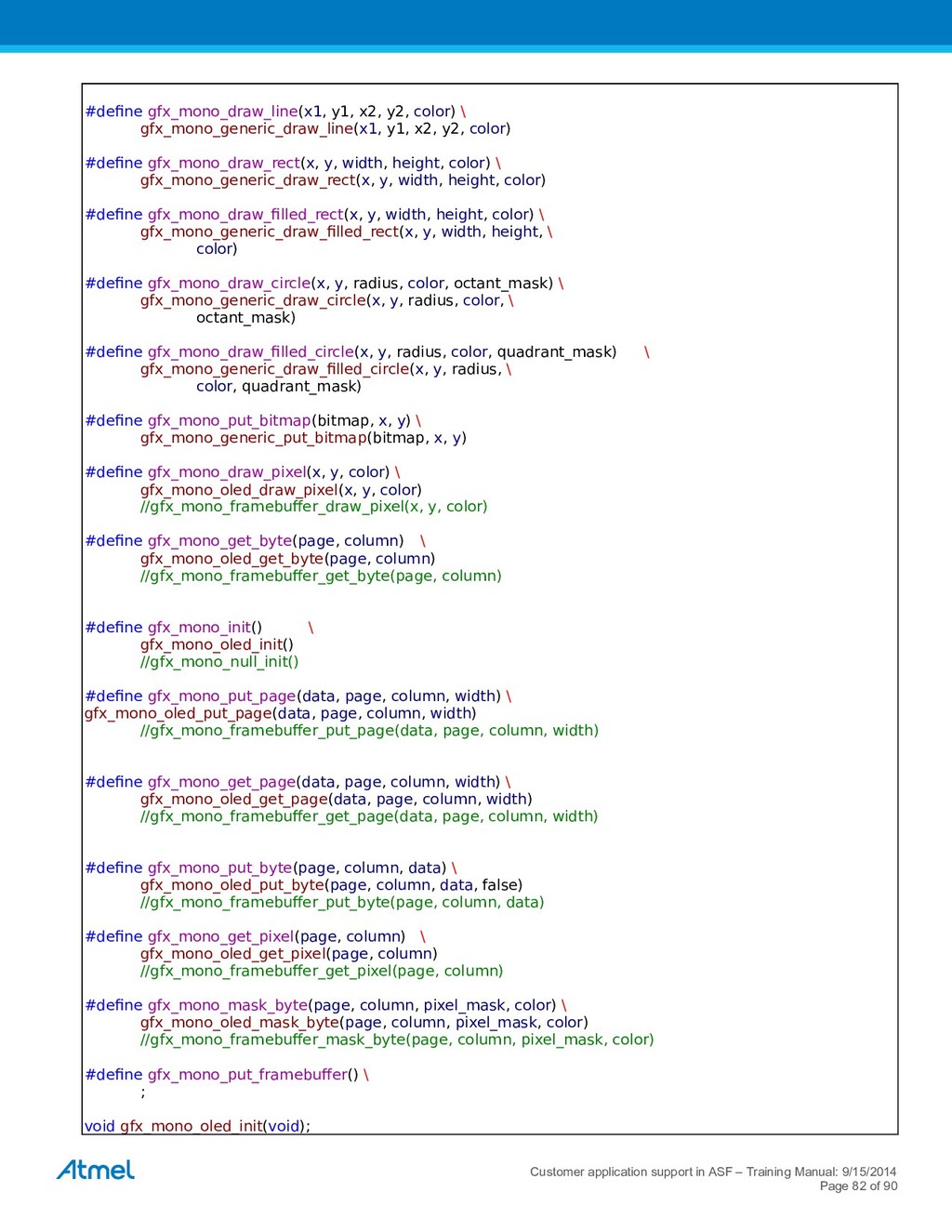
    y2, color) #define gfx_mono_draw_rect(x, y, width, height, color) \ gfx_mono_generic_draw_rect(x, y, width, height, color) #define gfx_mono_draw_filled_rect(x, y, width, height, color) \ gfx_mono_generic_draw_filled_rect(x, y, width, height, \ color) #define gfx_mono_draw_circle(x, y, radius, color, octant_mask) \ gfx_mono_generic_draw_circle(x, y, radius, color, \ octant_mask) #define gfx_mono_draw_filled_circle(x, y, radius, color, quadrant_mask) \ gfx_mono_generic_draw_filled_circle(x, y, radius, \ color, quadrant_mask) #define gfx_mono_put_bitmap(bitmap, x, y) \ gfx_mono_generic_put_bitmap(bitmap, x, y) #define gfx_mono_draw_pixel(x, y, color) \ gfx_mono_oled_draw_pixel(x, y, color) //gfx_mono_framebuffer_draw_pixel(x, y, color) #define gfx_mono_get_byte(page, column) \ gfx_mono_oled_get_byte(page, column) //gfx_mono_framebuffer_get_byte(page, column) #define gfx_mono_init() \ gfx_mono_oled_init() //gfx_mono_null_init() #define gfx_mono_put_page(data, page, column, width) \ gfx_mono_oled_put_page(data, page, column, width) //gfx_mono_framebuffer_put_page(data, page, column, width) #define gfx_mono_get_page(data, page, column, width) \ gfx_mono_oled_get_page(data, page, column, width) //gfx_mono_framebuffer_get_page(data, page, column, width) #define gfx_mono_put_byte(page, column, data) \ gfx_mono_oled_put_byte(page, column, data, false) //gfx_mono_framebuffer_put_byte(page, column, data) #define gfx_mono_get_pixel(page, column) \ gfx_mono_oled_get_pixel(page, column) //gfx_mono_framebuffer_get_pixel(page, column) #define gfx_mono_mask_byte(page, column, pixel_mask, color) \ gfx_mono_oled_mask_byte(page, column, pixel_mask, color) //gfx_mono_framebuffer_mask_byte(page, column, pixel_mask, color) #define gfx_mono_put_framebuffer() \ ; void gfx_mono_oled_init(void); Customer application support in ASF – Training Manual: 9/15/2014 Page 82 of 90
  82. //void gfx_mono_null_init(void); /** @} */ #ifdef __cplusplus } #endif /*

    declarations */ void gfx_mono_oled_draw_pixel(gfx_coord_t x,gfx_coord_t y,gfx_mono_color_t color); uint8_t gfx_mono_oled_get_byte(gfx_coord_t page, gfx_coord_t column); void gfx_mono_oled_put_byte(gfx_coord_t page, gfx_coord_t column, uint8_t data, bool force); uint8_t gfx_mono_oled_get_pixel(gfx_coord_t x, gfx_coord_t y); void gfx_mono_oled_put_page(gfx_mono_color_t *data, gfx_coord_t page, gfx_coord_t page_offset, gfx_coord_t width); void gfx_mono_oled_get_page(gfx_mono_color_t *data, gfx_coord_t page, gfx_coord_t page_offset, gfx_coord_t width); void gfx_mono_oled_mask_byte(gfx_coord_t page, gfx_coord_t column, gfx_mono_color_t pixel_mask, gfx_mono_color_t color); #endif /* GFX_MONO_NULL_H */ C.2 The body of the gfx_mono_null.c file #include "gfx_mono_null.h" /** * \ingroup asfdoc_common2_gfx_mono_null * @{ */ /* Memory for the framebuffer */ static uint8_t framebuffer[GFX_MONO_LCD_FRAMEBUFFER_SIZE]; /** * \brief Initialize NULL driver. */ void gfx_mono_null_init(void) { gfx_mono_set_framebuffer(framebuffer); } void gfx_mono_oled_draw_pixel(gfx_coord_t x, gfx_coord_t y, gfx_coord_t color) { uint8_t page; uint8_t pixel_mask; uint8_t pixel_value; /* Discard pixels drawn outside the screen */ if ((x > GFX_MONO_LCD_WIDTH - 1) || (y > GFX_MONO_LCD_HEIGHT - 1)) { return; } page = y / GFX_MONO_LCD_PIXELS_PER_BYTE; pixel_mask = (1 << (y - (page * 8))); /* * Read the page containing the pixel in interest, then perform the * requested action on this pixel before writing the page back to the Customer application support in ASF – Training Manual: 9/15/2014 Page 83 of 90
  83. * display. */ pixel_value = gfx_mono_get_byte(page, x); switch (color) {

    case GFX_PIXEL_SET: pixel_value |= pixel_mask; break; case GFX_PIXEL_CLR: pixel_value &= ~pixel_mask; break; case GFX_PIXEL_XOR: pixel_value ^= pixel_mask; break; default: break; } gfx_mono_put_byte(page, x, pixel_value); } uint8_t gfx_mono_oled_get_byte(gfx_coord_t page, gfx_coord_t column) { #ifdef CONFIG_OLED_FRAMEBUFFER return gfx_mono_framebuffer_get_byte(page, column); #else oled_set_page_address(page); oled_set_column_address(column); return oled_read_data(); #endif } void gfx_mono_oled_put_byte(gfx_coord_t page, gfx_coord_t column, uint8_t data, bool force) { #ifdef CONFIG_OLED_FRAMEBUFFER if (!force && data == gfx_mono_framebuffer_get_byte(page, column)) { return; } gfx_mono_framebuffer_put_byte(page, column, data); #endif oled_set_page_address(page); oled_set_column_address(column); oled_write_data(data); } uint8_t gfx_mono_oled_get_pixel(gfx_coord_t x, gfx_coord_t y) { uint8_t page; uint8_t pixel_mask; if ((x > GFX_MONO_LCD_WIDTH - 1) || (y > GFX_MONO_LCD_HEIGHT - 1)) { return 0; } Customer application support in ASF – Training Manual: 9/15/2014 Page 84 of 90
  84. page = y / GFX_MONO_LCD_PIXELS_PER_BYTE; pixel_mask = (1 << (y

    - (page * 8))); return gfx_mono_get_byte(page, x) & pixel_mask; } void gfx_mono_oled_get_page(gfx_mono_color_t *data, gfx_coord_t page, gfx_coord_t column, gfx_coord_t width) { #ifdef CONFIG_OLED_FRAMEBUFFER gfx_mono_framebuffer_get_page(data, page, column, width); #else oled_set_page_address(page); oled_set_column_address(column); do { *data++ = oled_read_data(); } while (--width); #endif } void gfx_mono_oled_mask_byte(gfx_coord_t page, gfx_coord_t column, gfx_mono_color_t pixel_mask, gfx_mono_color_t color) { gfx_mono_color_t temp = gfx_mono_get_byte(page, column); switch (color) { case GFX_PIXEL_SET: temp |= pixel_mask; break; case GFX_PIXEL_CLR: temp &= ~pixel_mask; break; case GFX_PIXEL_XOR: temp ^= pixel_mask; break; default: break; } gfx_mono_put_byte(page, column, temp); } void gfx_mono_oled_init(void) { uint8_t page; uint8_t column; #ifdef CONFIG_OLED_FRAMEBUFFER gfx_mono_set_framebuffer(framebuffer); #endif /* Initialize the low-level display controller. */ oled_init(); /* Set display to output data from line 0 */ oled_set_display_start_line_address(0); Customer application support in ASF – Training Manual: 9/15/2014 Page 85 of 90
  85. /* Clear the contents of the display. * If using

    a framebuffer (SPI interface) it will both clear the * controller memory and the framebuffer. */ for (page = 0; page < GFX_MONO_LCD_PAGES; page++) { for (column = 0; column < GFX_MONO_LCD_WIDTH; column++) { gfx_mono_oled_put_byte(page, column, 0x00, true); } } } Appendix D. Taking advantage of ASF conventions and APIs D.1 Peripheral module configuration As discussed in sections 1.7 and 1.9 configuring of the peripheral modules in the SAM-cortex –M0+ device family is a five step procedure. Let us recall it based on the ADC example: struct adc_module adc_instance; #define ADC_SAMPLES 1 uint16_t adc_result_buffer[ADC_SAMPLES]; void light_sensor_init(void) { struct adc_config config_adc; adc_get_config_defaults(&config_adc); config_adc.gain_factor= ADC_GAIN_FACTOR_DIV2; config_adc.clock_prescaler = ADC_CLOCK_PRESCALER_DIV512; config_adc.reference = ADC_REFERENCE_INTVCC1; config_adc.positive_input = ADC_POSITIVE_INPUT_PIN8; config_adc.resolution = ADC_RESOLUTION_12BIT; adc_init(&adc_instance, ADC, &config_adc); adc_enable(&adc_instance); When we use a driver in the callback mode, our procedure should also involve registering and enabling of the callback function. In these cases, it is logical to add the corresponding lines to the initialization function. adc_register_callback(&adc_instance, adc_complete_callback, ADC_CALLBACK_READ_BUFFER); Customer application support in ASF – Training Manual: 9/15/2014 Page 86 of 90 1. we create a configuration structure 2. we load the defualt values 3. we modify the defaults according to the needs of our application 4. we initialize the module to enforce the new configurations 5. we enable the module 6. registering the callback 7. enable the callback
  86. adc_enable_callback(&adc_instance, ADC_CALLBACK_READ_BUFFER); } Obviously, in order for the module to

    operate correctly, we need to define the body of the callback function as well as call the initialization function (light_sensor_init(); in our case) in the main program. D.2 The meaning of module instance and config struct’s. The ASF 3.0 convention predicts the existence of two kinds of structures: instances and configurations. Understating of their purpose is essential, if we wish to effectively and consciously use the ASF drivers. Instances are the first group of structures, whose purpose is to represent hardware peripheral modules in software. In order for the drivers to work correctly, they must be “linked” to physical modules they intend to operate on. The corresponding software structures are the collection of parameters describing the status of the modules under operation. These parameters could be, for example, a buffer containing data received through UART, a list of slaves assigned to a SPI master or an array of samples converted using ADC. The practical aspect of instances is easy to understand given the following example: let us assume that our application uses two SERCOM modules to communicate to two external units using USART. Naturally, we can use the SERCOM-USART driver available in ASF to handle this communication. However, without two separate instances representing to each SERCOM, the driver would not know which one of them is, for example, ready to ready data or which data buffer belongs to the particular module. Having the two instances we obtain a unique representation of the hardware and still able to use a single driver. Because instances represent the hardware modules that are in use, the corresponding structures should be declared as global. Especially, when a project is distributed over several files, we should make sure that instances are available to every function declared in the main program. In our case, our code involves a structure adc_instance of the adc_module type that is declared in main.c file outside any function. Configurations (or configs) are another kind of structures used in ASF. They are created to facilitate initializations and configurations of peripheral modules. Here, we are using config_adc of type adc_config, declared as local variable to the light_sensor_init(); function. It contains all the relevant parameters, whose definitions are needed to make the module operational. In contrary to instances, the config structures can be declared as either local or global and it depends on the character of an application which one we should choose. In principle, when a variable is declared locally memory spaced used to contain it is freed as soon as a corresponding function’s execution is finished. Consequently, if our application requires that a module is configured once (e.g. at the beginning of the program) and stays “unchanged”, it makes more sense to save memory by declaring the config structure locally. In some applications, however, it may be required that a module is reconfigured several times during the program execution. In these cases, it would be favorable to declare a global configuration structure and let the program use a fixed memory resource instead of dynamically allocate space at every occurrence of re- configuration. At this stage, you can observe that the link between the temporarily existing configuration structure and a “permanent” module instance is created by performing step #4 in the initialization process: adc_init(&adc_instance, ADC, &config_adc); In general, usage of structs for module configuration is a differentiating feature of ASF 3.0. It allows us – as users – to abstract from the register level code and memory maps and work with more user-friendly APIs. Instead of using arrays representing the registers and pointers to “navigate” over them, we can use config structures to more easily manipulate the settings and declare specific actions based on changes to instance structures, when necessary. This makes the code more transparent to the user and, at the same time, facilitates its portability. Customer application support in ASF – Training Manual: 9/15/2014 Page 87 of 90
  87. Revision History Doc. Rev. Date Comments A 10/2014 Initial document

    release *) Schematic for Arduino Zero board was not available online during the development of this training. Customer application support in ASF – Training Manual: 9/15/2014 Page 89 of 90
  88. Customer application support in ASF – Training Manual: 9/15/2014 Page

    90 of 90 Atmel Corporation 1600 Technology Drive, San Jose, CA 95110 USA T: (+1)(408) 441.0311 F: (+1)(408) 436.4200 │ www.atmel.com © 2014 Atmel Corporation. / Rev.: Error: Reference source not found – Training Manual: 9/15/2014. Atmel®, Atmel logo and combinations thereof, Enabling Unlimited Possibilities®, and others are registered trademarks or trademarks of Atmel Corporation in U.S. and other countries. ARM®, ARM Connected® logo, and others are the registered trademarks or trademarks of ARM Ltd. Other terms and product names may be trademarks of others. DISCLAIMER: The information in this document is provided in connection with Atmel products. No license, express or implied, by estoppel or otherwise, to any intellectual property right is granted by this document or in connection with the sale of Atmel products. EXCEPT AS SET FORTH IN THE ATMEL TERMS AND CONDITIONS OF SALES LOCATED ON THE ATMEL WEBSITE, ATMEL ASSUMES NO LIABILITY WHATSOEVER AND DISCLAIMS ANY EXPRESS, IMPLIED OR STATUTORY WARRANTY RELATING TO ITS PRODUCTS INCLUDING, BUT NOT LIMITED TO, THE IMPLIED WARRANTY OF MERCHANTABILITY, FITNESS FOR A PARTICULAR PURPOSE, OR NON-INFRINGEMENT. IN NO EVENT SHALL ATMEL BE LIABLE FOR ANY DIRECT, INDIRECT, CONSEQUENTIAL, PUNITIVE, SPECIAL OR INCIDENTAL DAMAGES (INCLUDING, WITHOUT LIMITATION, DAMAGES FOR LOSS AND PROFITS, BUSINESS INTERRUPTION, OR LOSS OF INFORMATION) ARISING OUT OF THE USE OR INABILITY TO USE THIS DOCUMENT, EVEN IF ATMEL HAS BEEN ADVISED OF THE POSSIBILITY OF SUCH DAMAGES. Atmel makes no representations or warranties with respect to the accuracy or completeness of the contents of this document and reserves the right to make changes to specifications and products descriptions at any time without notice. Atmel does not make any commitment to update the information contained herein. Unless specifically provided otherwise, Atmel products are not suitable for, and shall not be used in, automotive applications. Atmel products are not intended, authorized, or warranted for use as components in applications intended to support or sustain life. SAFETY-CRITICAL, MILITARY, AND AUTOMOTIVE APPLICATIONS DISCLAIMER: Atmel products are not designed for and will not be used in connection with any applications where the failure of such products would reasonably be expected to result in significant personal injury or death (“Safety-Critical Applications”) without an Atmel officer's specific written consent. Safety-Critical Applications include, without limitation, life support devices and systems, equipment or systems for the operation of nuclear facilities and weapons systems. Atmel products are not designed nor intended for use in military or aerospace applications or environments unless specifically designated by Atmel as military-grade. Atmel products are not designed nor intended for use in automotive applications unless specifically designated by Atmel as automotive-grade.