Upgrade to Pro — share decks privately, control downloads, hide ads and more …

Long-Range Appliance Control Using Arduino and ...

Long-Range Appliance Control Using Arduino and RYLR999 LoRa Module

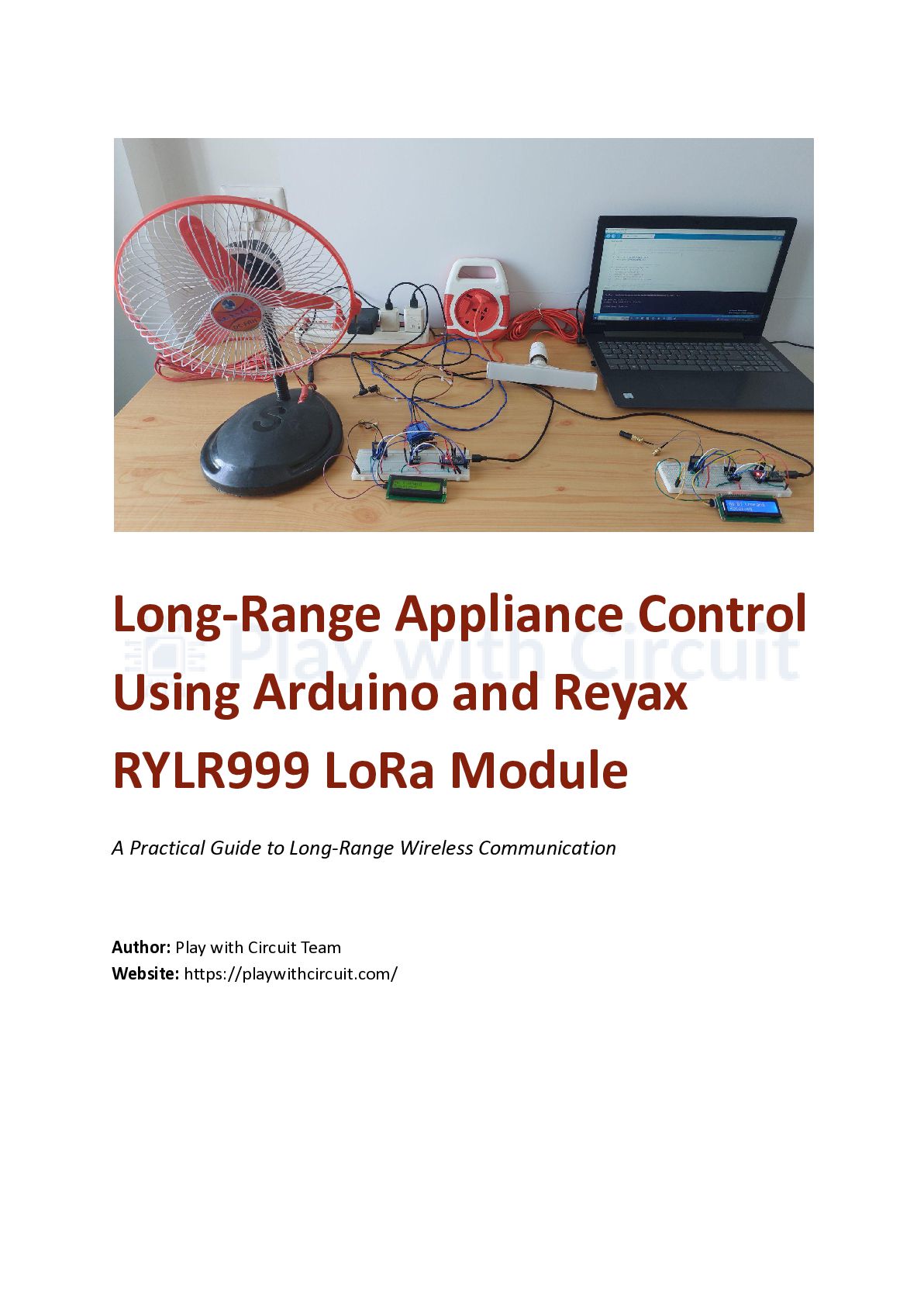
This document presents the design and implementation of a long-range wireless appliance control system based on Arduino Nano and Reyax RYLR999 LoRa modules. The project utilizes Bluetooth Low Energy and LoRa communication to remotely control electrical loads and demonstrates practical concepts related to IoT, relay interfacing, and wireless automation.

Avatar for Play with Circuit

Play with Circuit

June 22, 2026

Other Decks in Programming

Transcript

  1. Long-Range Appliance Control Using Arduino and Reyax RYLR999 LoRa Module

    A Practical Guide to Long-Range Wireless Communication Author: Play with Circuit Team​ Website: https://playwithcircuit.com/
  2. Table of Content Long-Range Appliance Control Using Arduino and RYLR999

    LoRa Module Introduction Project Overview Controller Node Target Node Understanding the RYLR999 Module Hardware Components Arduino Nano (2) RYLR999 Module (2) Bidirectional Voltage Level Shifter (2) 16×2 I2C LCD Display (2) Two-Channel Relay Module 12V DC Fan 240V AC Bulb Why Are Relays Used? System Architecture Controller Setup Connections Target Setup Connections Command Structure Working Principle Testing the System Testing BLE Communication Testing LoRa Transmission Testing Relay Operation LCD Monitoring Experimental Observations Applications Future Enhancements Conclusion Additional Resources About Play with Circuit
  3. Introduction Imagine being able to control an electrical appliance located

    far away—perhaps in another room, another building, or even several kilometers away—simply using your smartphone. Without relying on Wi-Fi, internet connectivity, or long wires, LoRa communication makes this possible by providing reliable long-distance wireless communication while consuming very little power. In this project, we build a long-range appliance control system using Arduino Nano and the Reyax RYLR999 module. Commands sent from a smartphone are first received over Bluetooth Low Energy (BLE) and then transmitted over LoRa to another node, where appliances such as a lamp and a fan are controlled through relays. To monitor communication status, 16×2 I2C LCD displays are used to show commands and response messages. This makes the system easy to test and troubleshoot. Project Overview The system consists of two independent sections: Controller Node The controller node acts as the gateway between the smartphone and the LoRa network. It receives commands from the smartphone through BLE and forwards them to the LoRa transmitter. Target Node The target node receives LoRa messages and controls appliances using relay modules. It also sends a response back to confirm successful operation. Understanding the RYLR999 Module The Reyax RYLR999 combines Bluetooth Low Energy and LoRa communication in a single compact module. In this project: •​ BLE is used for communication with the smartphone.
  4. •​ LoRa is used for long-distance transmission. •​ The module

    communicates with Arduino using UART serial communication. Because of its dual functionality, the module eliminates the need for separate BLE and LoRa hardware. Hardware Components The following components are used in this project: Arduino Nano (2) Acts as the main controller for both nodes. RYLR999 Module (2) Provides BLE and LoRa communication. Bidirectional Voltage Level Shifter (2) Safely interfaces the 5V Arduino with the 3.3V communication module. 16×2 I2C LCD Display (2) Displays commands and communication status. Two-Channel Relay Module Controls the connected electrical loads. 12V DC Fan Used as a DC load. 240V AC Bulb Used as an AC load.
  5. Why Are Relays Used? Arduino operates at low voltage and

    cannot directly switch high-voltage or high-current loads. The relay acts as an electrically controlled switch that allows the Arduino to safely control: •​ AC bulbs •​ DC fans •​ Pumps •​ Motors Relays provide electrical isolation between the control circuit and the load. System Architecture The communication flow is: Smartphone ↓ Bluetooth Low Energy ↓ Controller Node ↓ LoRa Communication ↓ Target Node ↓ Relay Module ↓ Electrical Appliance
  6. ↓ Response Message ↓ LCD Display Controller Setup Connections The

    controller setup consists of an Arduino Nano, an RYLR999 module, a voltage level shifter, and a 16×2 LCD. The module is powered from the Arduino 5V supply. Since the RYLR999 operates with 3.3V logic, a bidirectional level shifter is used between the Arduino and the module. The LoRa transmit and receive pins are connected to the Arduino hardware serial interface. The LCD communicates through the I2C interface using A4 and A5 pins. The display shows: •​ Initialization status
  7. •​ Received BLE commands •​ LoRa transmission messages •​ Acknowledgment

    responses Target Setup Connections The target node contains another Arduino Nano and an RYLR999 module. Unlike the controller setup, BLE communication is not used here. The LoRa module continuously listens for incoming messages. The relay module is connected to: •​ D11 → Bulb control •​ D12 → Fan control The target LCD displays:
  8. •​ Received commands •​ Relay status •​ Response messages Command

    Structure The following commands are sent from the LightBlue BLE application: *L1# → Turn bulb ON *L0# → Turn bulb OFF *F1# → Turn fan ON *F0# → Turn fan OFF After successful execution, the receiver returns: DONE Working Principle 1.​ A command is sent from the smartphone. 2.​ The BLE interface receives the command. 3.​ Arduino processes the command. 4.​ The LoRa module transmits the message. 5.​ The receiver node receives the data. 6.​ Arduino interprets the command. 7.​ The relay activates. 8.​ The appliance switches ON or OFF. 9.​ A confirmation response is sent back. 10.​LCD displays update accordingly. Testing the System After uploading the firmware: Testing BLE Communication
  9. Connect to the RYLR999 module using the LightBlue application and

    verify that commands are received. Testing LoRa Transmission Ensure that the target node receives the commands correctly. Testing Relay Operation Verify that the bulb and fan respond to commands. LCD Monitoring Observe LCD messages for communication status and confirmation responses. Experimental Observations During testing, the following observations were made: •​ BLE communication worked reliably. •​ Commands were transmitted successfully over LoRa. •​ LCD displays simplified debugging. •​ Relay switching was stable. •​ The system provided immediate feedback through acknowledgment messages. Applications This system can be used in: •​ Smart agriculture •​ Irrigation systems •​ Remote lighting •​ Industrial automation •​ Warehouse control •​ Off-grid IoT systems Future Enhancements Possible improvements include:
  10. •​ Multiple receiver nodes •​ Sensor integration •​ Mobile application

    development •​ Solar-powered operation •​ Battery backup •​ Data logging •​ Cloud connectivity Conclusion This project demonstrates how Bluetooth Low Energy and LoRa communication can be combined to create a practical long-range wireless control system. The architecture is flexible, scalable, and suitable for many IoT and automation applications where internet connectivity may not be available. Additional Resources Complete source code, circuit diagrams, and configuration details are available at: https://playwithcircuit.com/long-range-appliance-control-from-smartphone-using-arduin o/ About Play with Circuit Play with Circuit is an educational platform dedicated to Arduino, embedded systems, ESP32 and electronics tutorials. The website provides practical guides, projects, and technical articles aimed at students, hobbyists and engineers interested in learning electronics and developing real-world applications.