virtual IPv6 addresses Ren Goto1), Kazushige Matama1), Chihiro Nishiwaki1), Katsuhiro Naito2) 1) Graduate School of Business Administration and Computer Science, Aichi Institute of Technology 2) Faculty of Information Science, Aichi Institute of Technology 2022, October, 18 The 11th Global Conference on Consumer Electronics: GCCE 2022 1
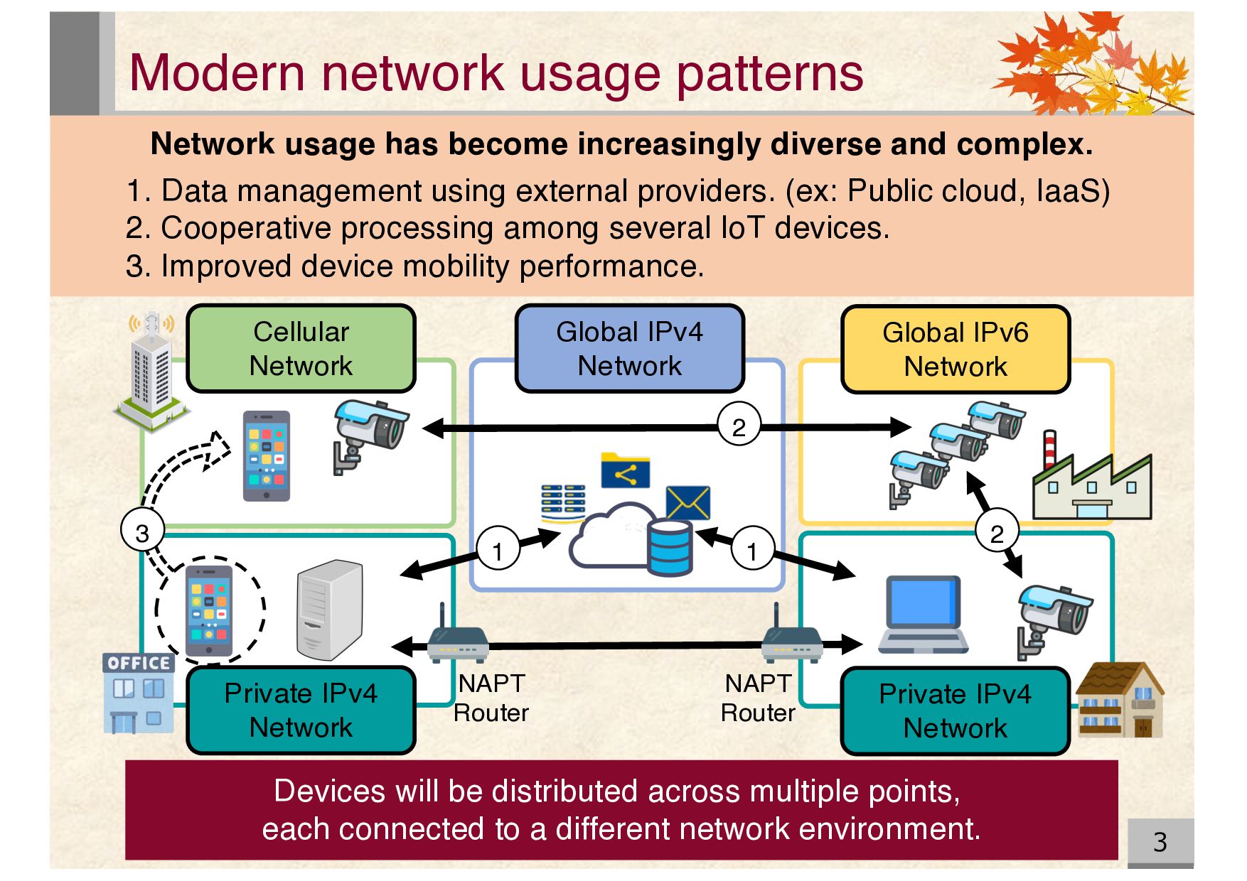
diverse and complex. Devices will be distributed across multiple points, each connected to a different network environment. Global IPv6 Network Global IPv4 Network Cellular Network Private IPv4 Network Private IPv4 Network 2 3 1 1 1. Data management using external providers. (ex: Public cloud, IaaS) 2. Cooperative processing among several IoT devices. 3. Improved device mobility performance. NAPT Router NAPT Router 2
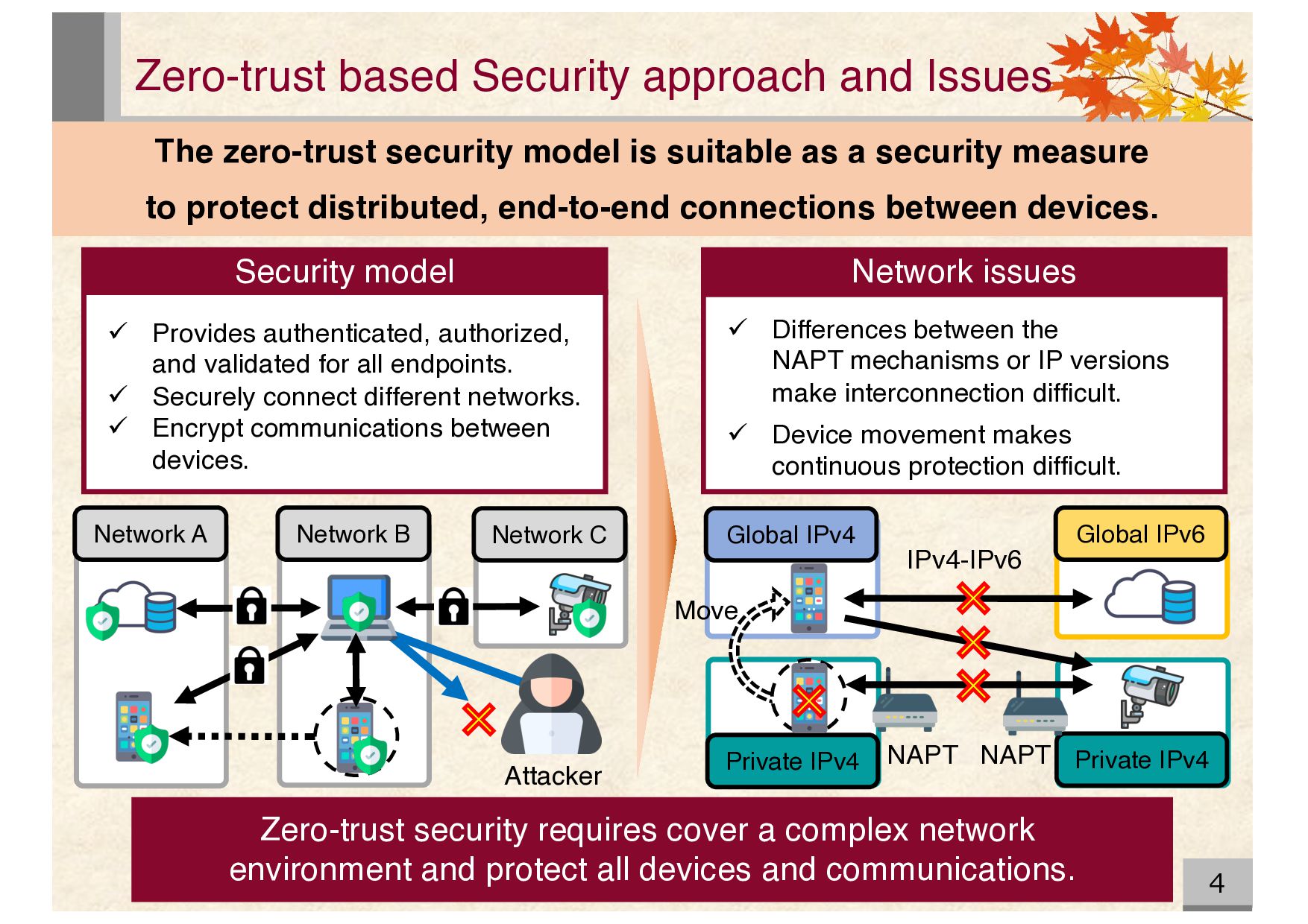
cover a complex network environment and protect all devices and communications. The zero-trust security model is suitable as a security measure to protect distributed, end-to-end connections between devices. ü Provides authenticated, authorized, and validated for all endpoints. ü Securely connect different networks. ü Encrypt communications between devices. Security model Network issues ü Differences between the NAPT mechanisms or IP versions make interconnection difficult. ü Device movement makes continuous protection difficult. Attacker Network A Network B Network C Global IPv4 Private IPv4 Global IPv6 Private IPv4 NAPT NAPT IPv4-IPv6 Move
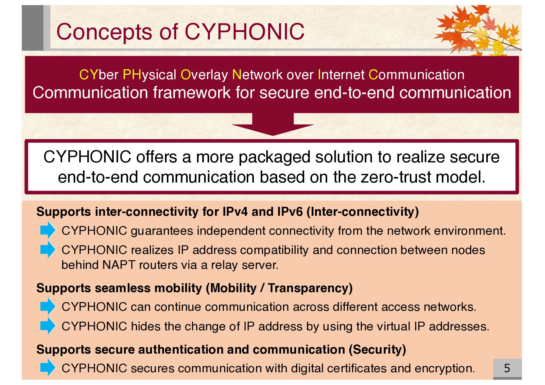
to realize secure end-to-end communication based on the zero-trust model. CYber PHysical Overlay Network over Internet Communication Communication framework for secure end-to-end communication Supports inter-connectivity for IPv4 and IPv6 (Inter-connectivity) CYPHONIC guarantees independent connectivity from the network environment. CYPHONIC realizes IP address compatibility and connection between nodes behind NAPT routers via a relay server. Supports seamless mobility (Mobility / Transparency) CYPHONIC can continue communication across different access networks. CYPHONIC hides the change of IP address by using the virtual IP addresses. Supports secure authentication and communication (Security) CYPHONIC secures communication with digital certificates and encryption.
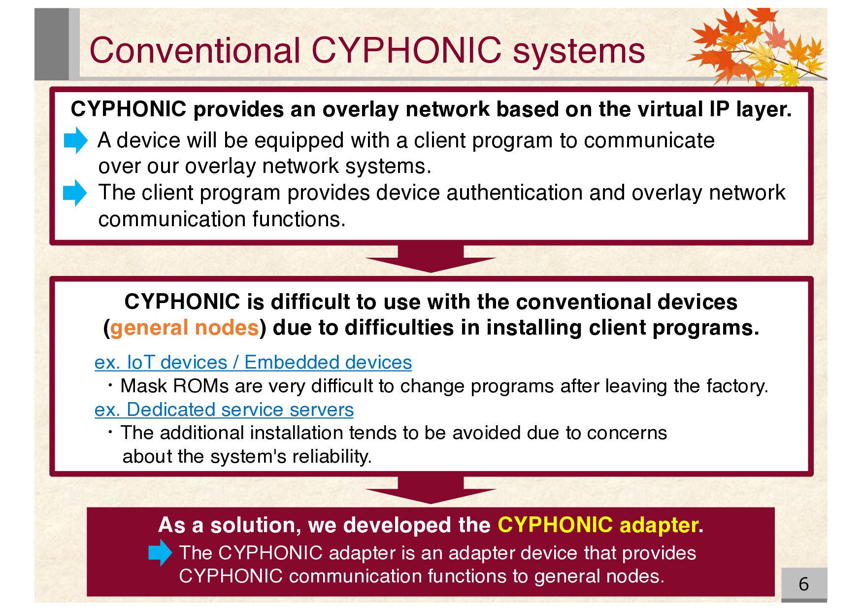
the conventional devices (general nodes) due to difficulties in installing client programs. ex. IoT devices / Embedded devices ・Mask ROMs are very difficult to change programs after leaving the factory. ex. Dedicated service servers ・The additional installation tends to be avoided due to concerns about the system's reliability. CYPHONIC provides an overlay network based on the virtual IP layer. A device will be equipped with a client program to communicate over our overlay network systems. The client program provides device authentication and overlay network communication functions. As a solution, we developed the CYPHONIC adapter. The CYPHONIC adapter is an adapter device that provides CYPHONIC communication functions to general nodes.
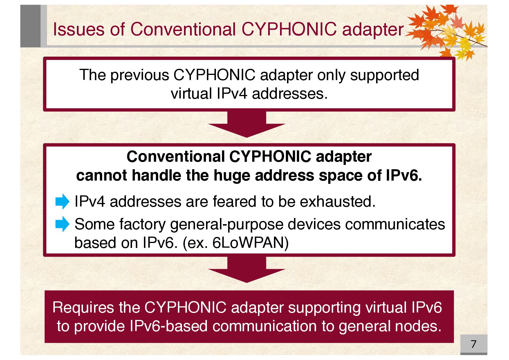
only supported virtual IPv4 addresses. Conventional CYPHONIC adapter cannot handle the huge address space of IPv6. IPv4 addresses are feared to be exhausted. Some factory general-purpose devices communicates based on IPv6. (ex. 6LoWPAN) Requires the CYPHONIC adapter supporting virtual IPv6 to provide IPv6-based communication to general nodes.
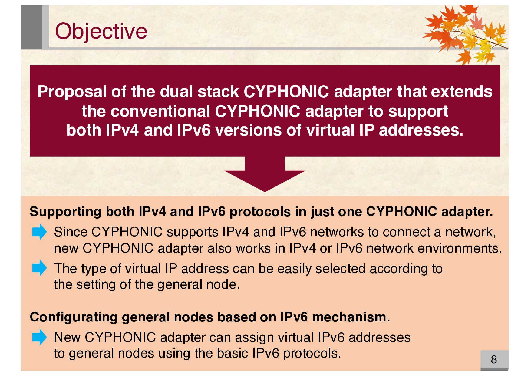
extends the conventional CYPHONIC adapter to support both IPv4 and IPv6 versions of virtual IP addresses. Supporting both IPv4 and IPv6 protocols in just one CYPHONIC adapter. Since CYPHONIC supports IPv4 and IPv6 networks to connect a network, new CYPHONIC adapter also works in IPv4 or IPv6 network environments. The type of virtual IP address can be easily selected according to the setting of the general node. Configurating general nodes based on IPv6 mechanism. New CYPHONIC adapter can assign virtual IPv6 addresses to general nodes using the basic IPv6 protocols.
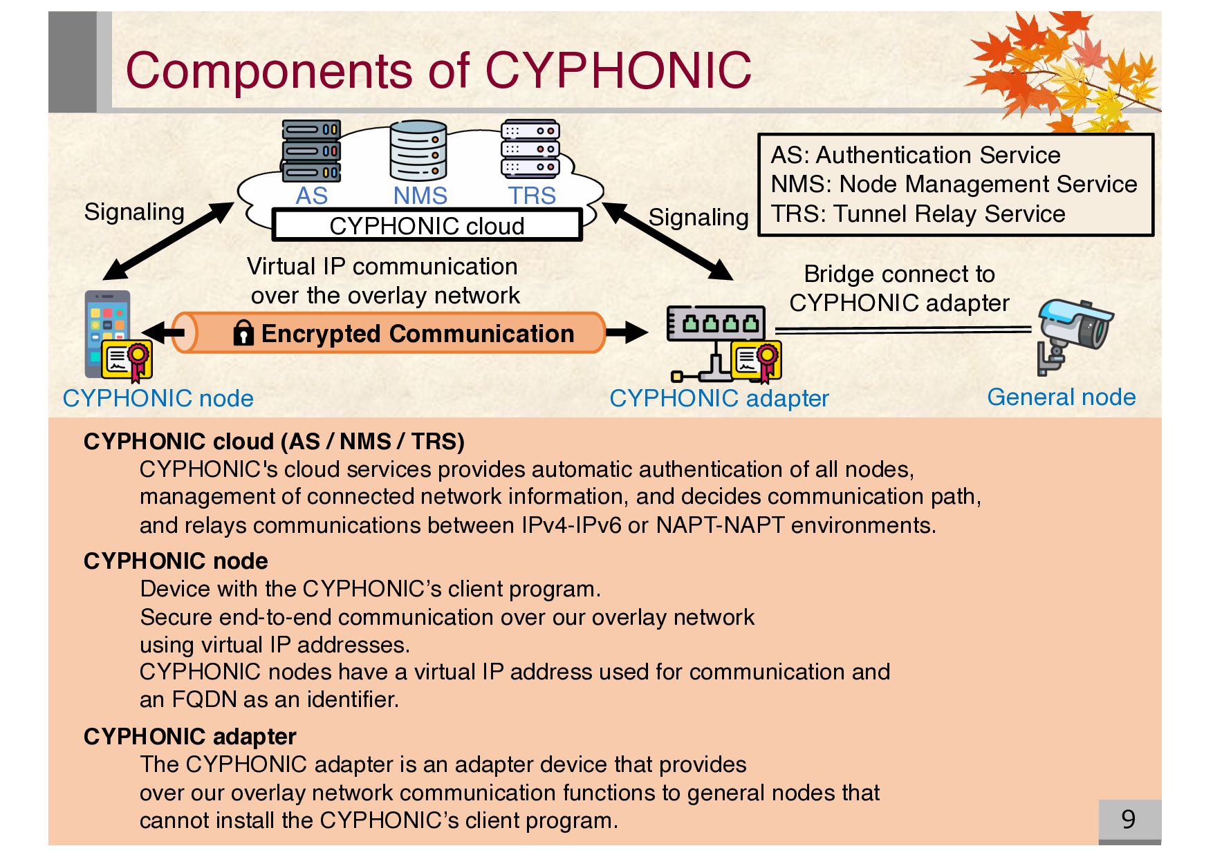
TRS) CYPHONIC's cloud services provides automatic authentication of all nodes, management of connected network information, and decides communication path, and relays communications between IPv4-IPv6 or NAPT-NAPT environments. CYPHONIC node Device with the CYPHONIC’s client program. Secure end-to-end communication over our overlay network using virtual IP addresses. CYPHONIC nodes have a virtual IP address used for communication and an FQDN as an identifier. CYPHONIC adapter The CYPHONIC adapter is an adapter device that provides over our overlay network communication functions to general nodes that cannot install the CYPHONIC’s client program. Signaling TRS NMS AS CYPHONIC cloud CYPHONIC node CYPHONIC adapter Virtual IP communication over the overlay network Encrypted Communication General node Signaling Bridge connect to CYPHONIC adapter AS: Authentication Service NMS: Node Management Service TRS: Tunnel Relay Service
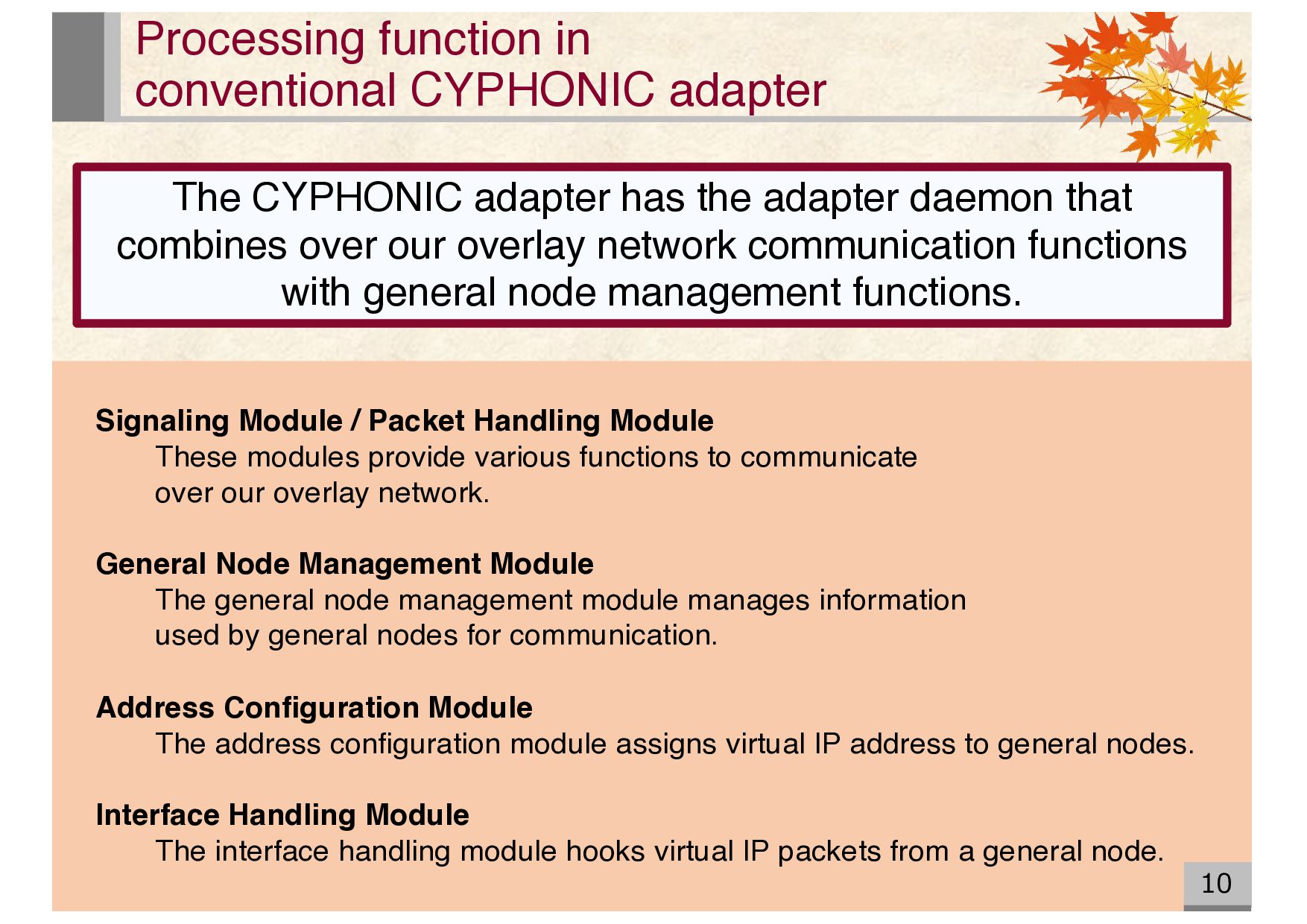
Packet Handling Module These modules provide various functions to communicate over our overlay network. General Node Management Module The general node management module manages information used by general nodes for communication. Address Configuration Module The address configuration module assigns virtual IP address to general nodes. Interface Handling Module The interface handling module hooks virtual IP packets from a general node. The CYPHONIC adapter has the adapter daemon that combines over our overlay network communication functions with general node management functions.
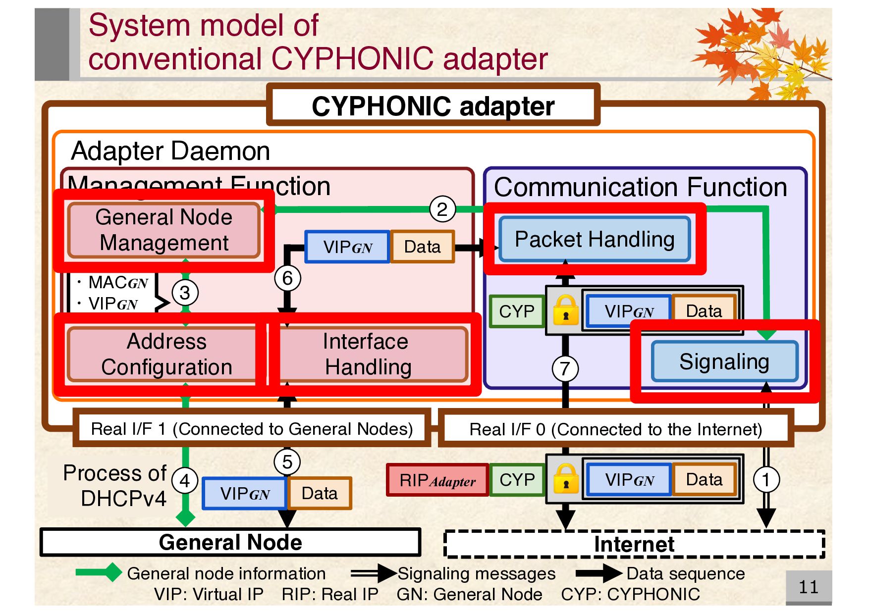
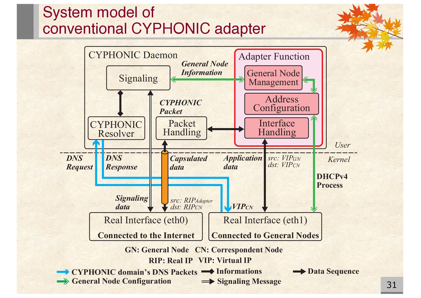
General Node Management Interface Handling Address Configuration Communication Function Packet Handling Signaling VIP: Virtual IP RIP: Real IP GN: General Node CYP: CYPHONIC VIPGN Data ・MACGN ・VIPGN General node information Signaling messages Data sequence VIPGN Data CYP VIPGN Data CYP VIPGN Data RIPAdapter 1 2 3 4 5 6 7 System model of conventional CYPHONIC adapter Real I/F 1 (Connected to General Nodes) Real I/F 0 (Connected to the Internet) Internet General Node
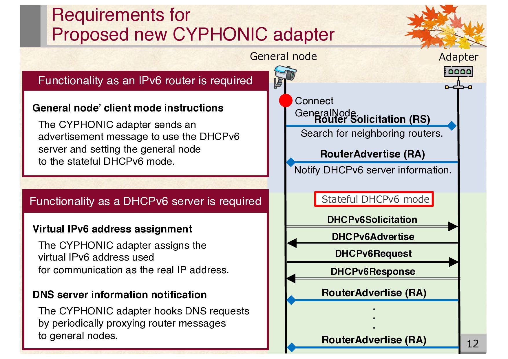
DHCPv6Request DHCPv6Response Connect GeneralNode. Stateful DHCPv6 mode Search for neighboring routers. Notify DHCPv6 server information. Adapter RouterAdvertise (RA) RouterAdvertise (RA) ・ ・ ・ Virtual IPv6 address assignment The CYPHONIC adapter assigns the virtual IPv6 address used for communication as the real IP address. DNS server information notification The CYPHONIC adapter hooks DNS requests by periodically proxying router messages to general nodes. General node’ client mode instructions The CYPHONIC adapter sends an advertisement message to use the DHCPv6 server and setting the general node to the stateful DHCPv6 mode. Functionality as an IPv6 router is required Requirements for Proposed new CYPHONIC adapter Functionality as a DHCPv6 server is required
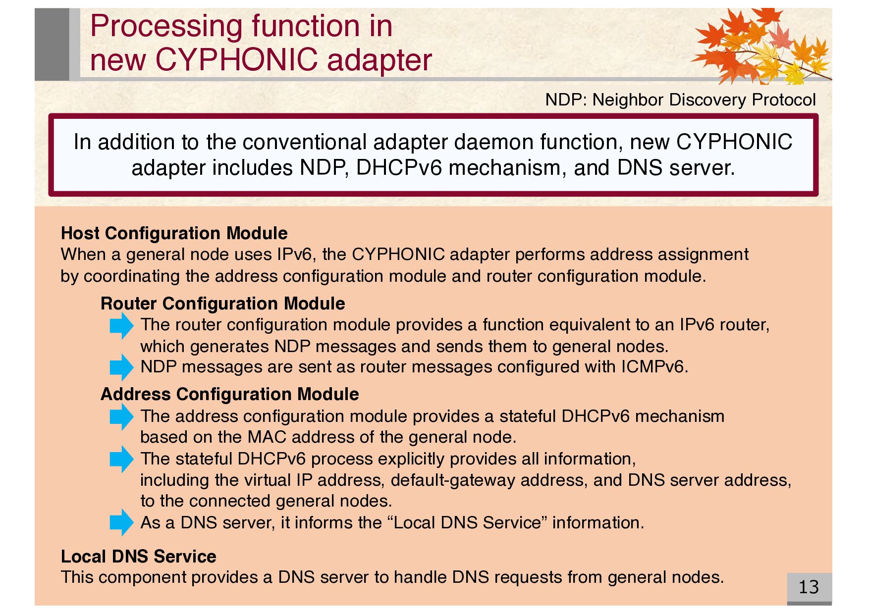
When a general node uses IPv6, the CYPHONIC adapter performs address assignment by coordinating the address configuration module and router configuration module. Router Configuration Module The router configuration module provides a function equivalent to an IPv6 router, which generates NDP messages and sends them to general nodes. NDP messages are sent as router messages configured with ICMPv6. Address Configuration Module The address configuration module provides a stateful DHCPv6 mechanism based on the MAC address of the general node. The stateful DHCPv6 process explicitly provides all information, including the virtual IP address, default-gateway address, and DNS server address, to the connected general nodes. As a DNS server, it informs the “Local DNS Service” information. Local DNS Service This component provides a DNS server to handle DNS requests from general nodes. NDP: Neighbor Discovery Protocol In addition to the conventional adapter daemon function, new CYPHONIC adapter includes NDP, DHCPv6 mechanism, and DNS server.
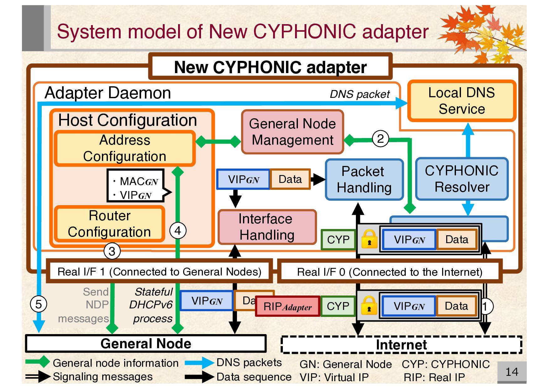
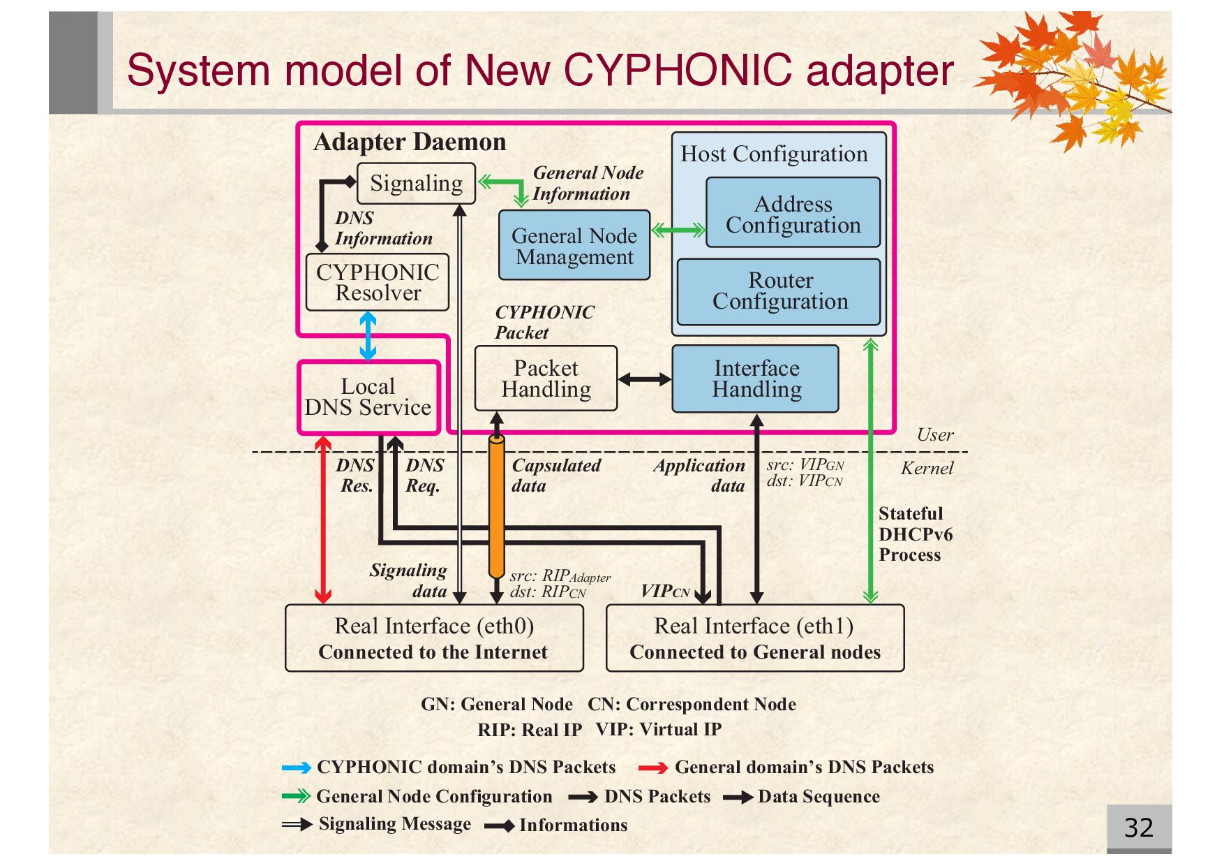
adapter Adapter Daemon Host Configuration General Node Management Address Configuration Packet Handling Signaling General Node GN: General Node CYP: CYPHONIC VIP: Virtual IP RIP: Real IP ・MACGN ・VIPGN General node information 1 Router Configuration DNS packet Interface Handling Local DNS Service CYPHONIC Resolver Real I/F 1 (Connected to General Nodes) Real I/F 0 (Connected to the Internet) 2 VIPGN Data VIPGN Data CYP VIPGN Data CYP VIPGN Data RIPAdapter 3 4 5 Data sequence DNS packets Signaling messages System model of New CYPHONIC adapter
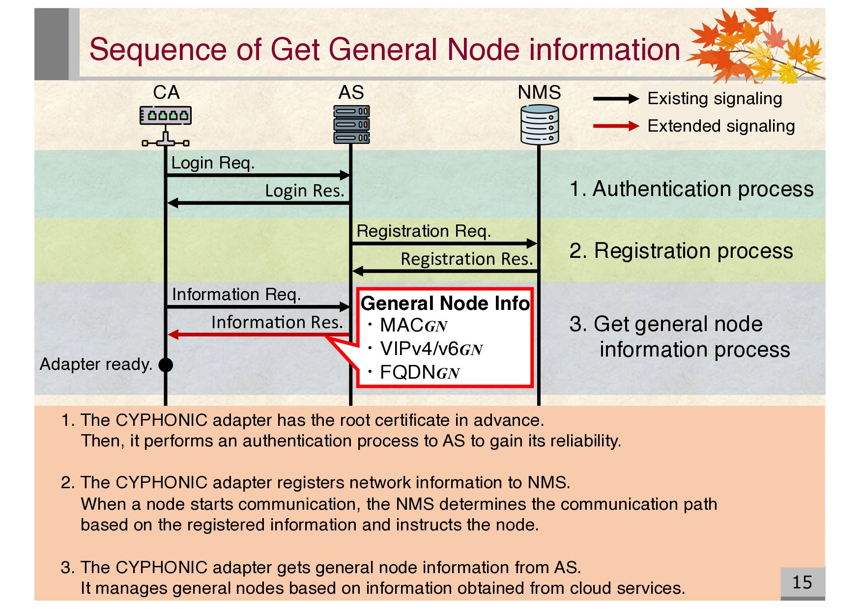
15 NMS AS CA Login Res. Registration Res. Information Req. Informa1on Res. Adapter ready. General Node Info ・MACGN ・VIPv4/v6GN ・FQDNGN 1. Authentication process 2. Registration process 3. Get general node information process Existing signaling Extended signaling 1. The CYPHONIC adapter has the root certificate in advance. Then, it performs an authentication process to AS to gain its reliability. 2. The CYPHONIC adapter registers network information to NMS. When a node starts communication, the NMS determines the communication path based on the registered information and instructs the node. 3. The CYPHONIC adapter gets general node information from AS. It manages general nodes based on information obtained from cloud services.
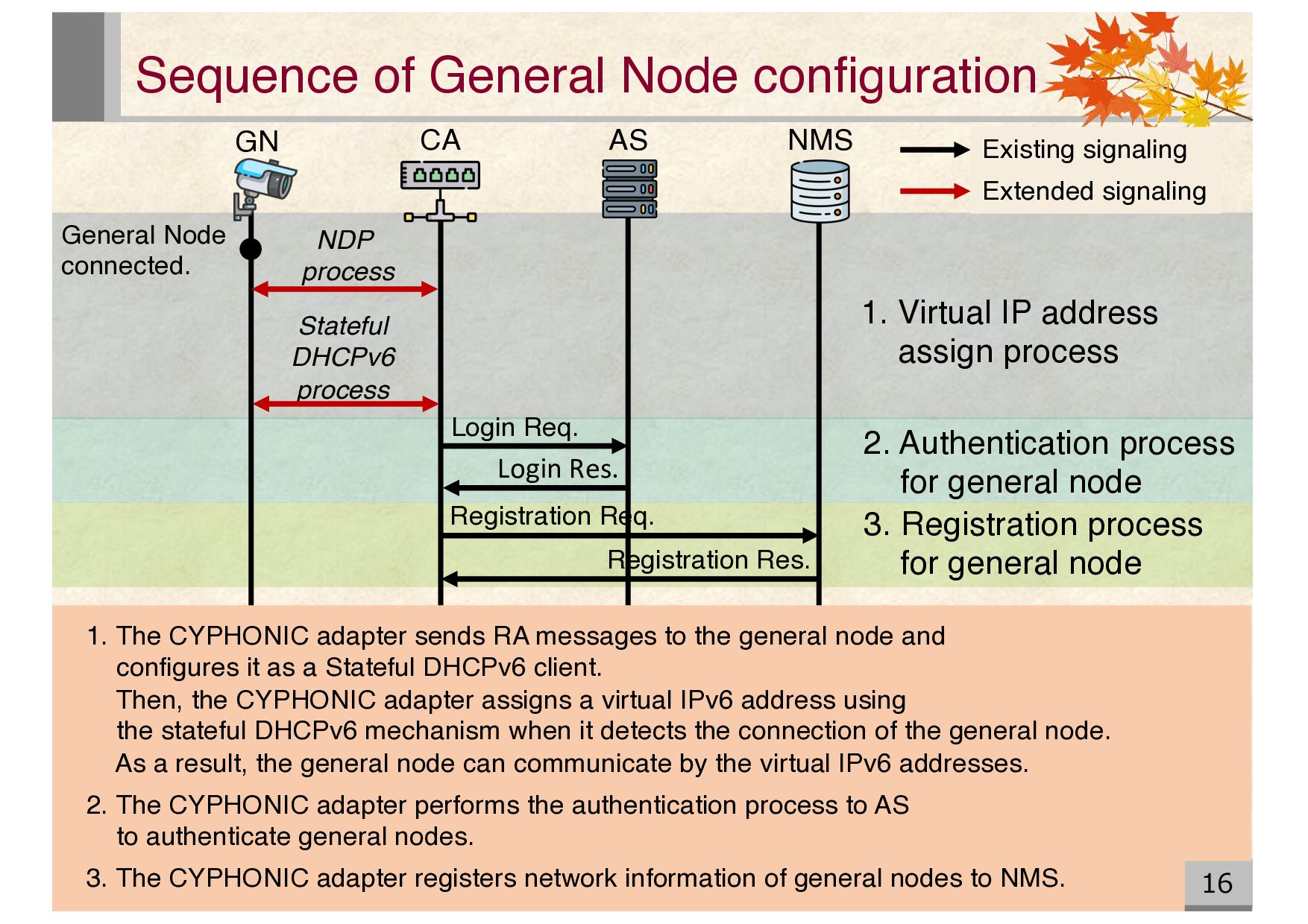
General Node connected. Stateful DHCPv6 process Login Req. Login Res. Registration Req. Registration Res. 2. Authentication process for general node 3. Registration process for general node 1. Virtual IP address assign process NDP process Existing signaling Extended signaling 1. The CYPHONIC adapter sends RA messages to the general node and configures it as a Stateful DHCPv6 client. Then, the CYPHONIC adapter assigns a virtual IPv6 address using the stateful DHCPv6 mechanism when it detects the connection of the general node. As a result, the general node can communicate by the virtual IPv6 addresses. 2. The CYPHONIC adapter performs the authentication process to AS to authenticate general nodes. 3. The CYPHONIC adapter registers network information of general nodes to NMS.
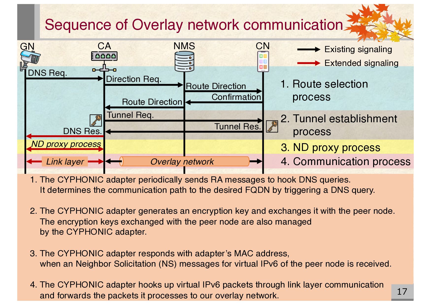
Direction Sequence of Overlay network communication 17 NMS CA GN CN DNS Req. Direction Req. Confirmation Tunnel Req. Tunnel Res. DNS Res. Link layer Overlay network 1. Route selection process 2. Tunnel establishment process 3. ND proxy process 4. Communication process 1. The CYPHONIC adapter periodically sends RA messages to hook DNS queries. It determines the communication path to the desired FQDN by triggering a DNS query. 2. The CYPHONIC adapter generates an encryption key and exchanges it with the peer node. The encryption keys exchanged with the peer node are also managed by the CYPHONIC adapter. 3. The CYPHONIC adapter responds with adapter’s MAC address, when an Neighbor Solicitation (NS) messages for virtual IPv6 of the peer node is received. 4. The CYPHONIC adapter hooks up virtual IPv6 packets through link layer communication and forwards the packets it processes to our overlay network.
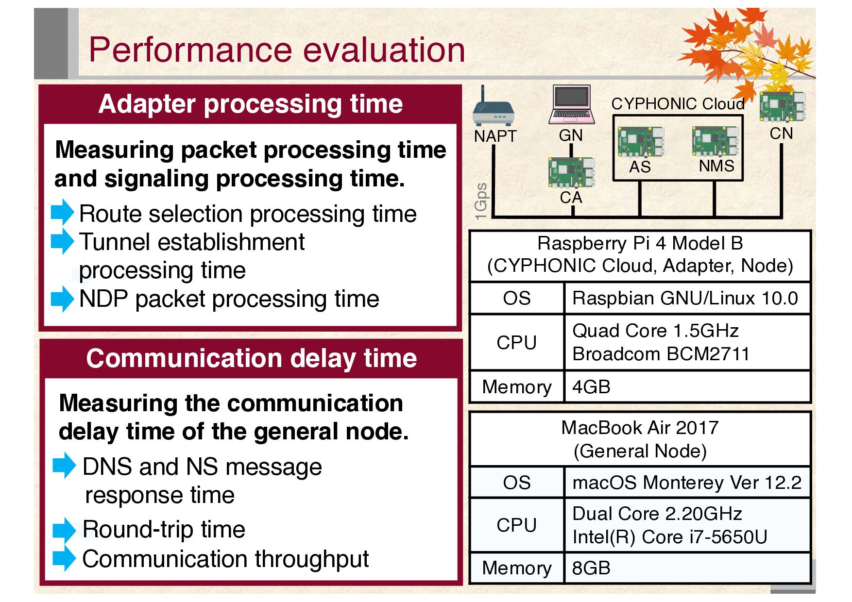
B (CYPHONIC Cloud, Adapter, Node) OS Raspbian GNU/Linux 10.0 CPU Quad Core 1.5GHz Broadcom BCM2711 Memory 4GB MacBook Air 2017 (General Node) OS macOS Monterey Ver 12.2 CPU Dual Core 2.20GHz Intel(R) Core i7-5650U Memory 8GB CA GN AS NMS CN CYPHONIC Cloud 1Gps NAPT Communication delay time Measuring the communication delay time of the general node. DNS and NS message response time Round-trip time Communication throughput Measuring packet processing time and signaling processing time. Route selection processing time Tunnel establishment processing time NDP packet processing time
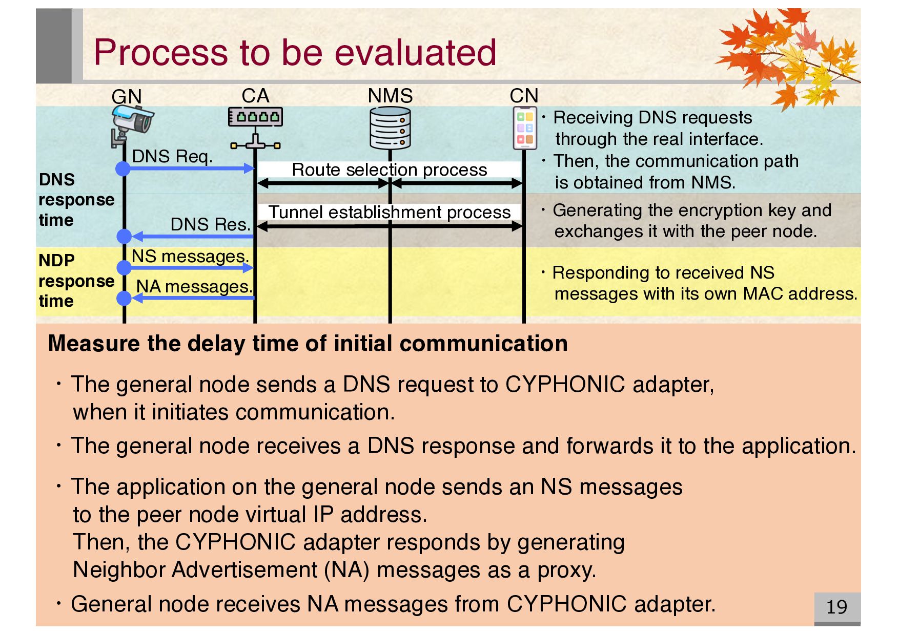
node. Process to be evaluated 19 ・Receiving DNS requests through the real interface. ・Then, the communication path is obtained from NMS. ・Responding to received NS messages with its own MAC address. NMS CA GN CN DNS response time NDP response time Route selection process Tunnel establishment process NS messages. NA messages. DNS Res. DNS Req. Measure the delay time of initial communication ・The general node sends a DNS request to CYPHONIC adapter, when it initiates communication. ・The general node receives a DNS response and forwards it to the application. ・The application on the general node sends an NS messages to the peer node virtual IP address. Then, the CYPHONIC adapter responds by generating Neighbor Advertisement (NA) messages as a proxy. ・General node receives NA messages from CYPHONIC adapter.
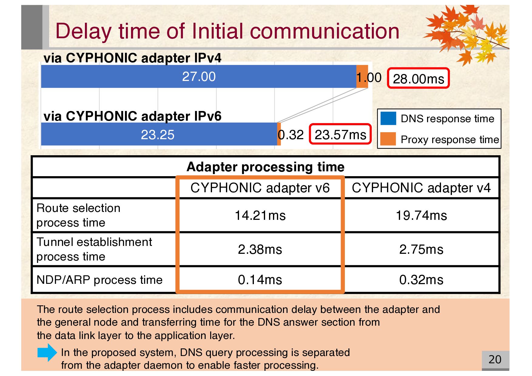
selection process time 14.21ms 19.74ms Tunnel establishment process time 2.38ms 2.75ms NDP/ARP process time 0.14ms 0.32ms 20 Delay time of Initial communication DNS response time Proxy response time via CYPHONIC adapter IPv4 via CYPHONIC adapter IPv6 27.00 23.25 1.00 0.32 23.57ms 28.00ms The route selection process includes communication delay between the adapter and the general node and transferring time for the DNS answer section from the data link layer to the application layer. In the proposed system, DNS query processing is separated from the adapter daemon to enable faster processing.
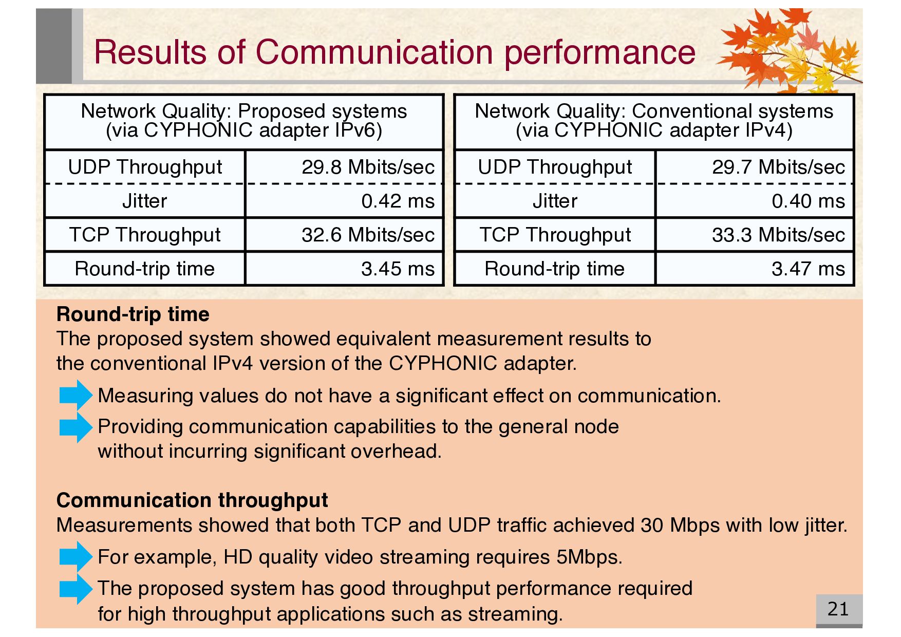
CYPHONIC adapter IPv6) UDP Throughput 29.8 Mbits/sec Jitter 0.42 ms TCP Throughput 32.6 Mbits/sec Round-trip time 3.45 ms Network Quality: Conventional systems (via CYPHONIC adapter IPv4) UDP Throughput 29.7 Mbits/sec Jitter 0.40 ms TCP Throughput 33.3 Mbits/sec Round-trip time 3.47 ms Round-trip time The proposed system showed equivalent measurement results to the conventional IPv4 version of the CYPHONIC adapter. Measuring values do not have a significant effect on communication. Providing communication capabilities to the general node without incurring significant overhead. Communication throughput Measurements showed that both TCP and UDP traffic achieved 30 Mbps with low jitter. For example, HD quality video streaming requires 5Mbps. The proposed system has good throughput performance required for high throughput applications such as streaming.
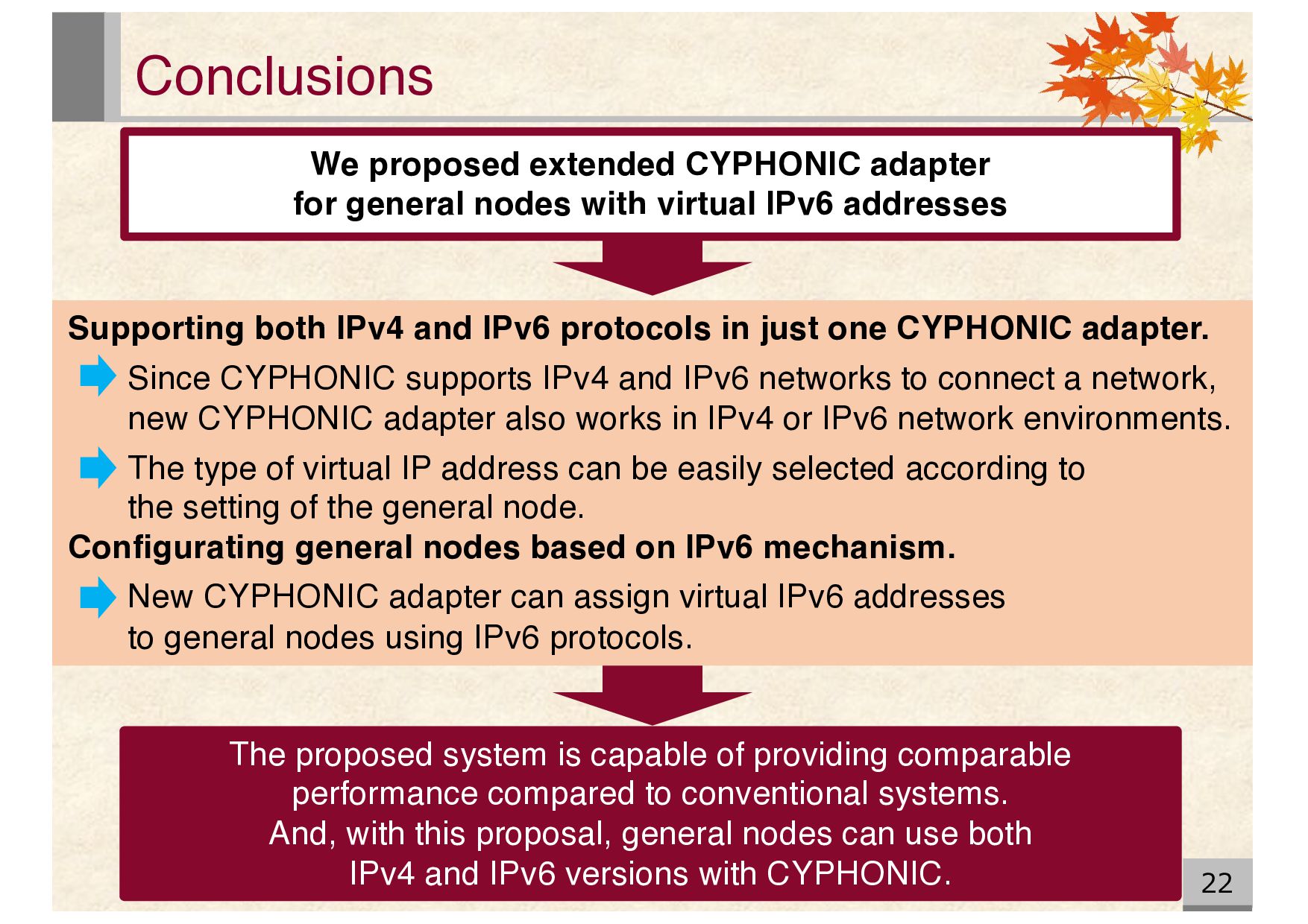
with virtual IPv6 addresses The proposed system is capable of providing comparable performance compared to conventional systems. And, with this proposal, general nodes can use both IPv4 and IPv6 versions with CYPHONIC. Supporting both IPv4 and IPv6 protocols in just one CYPHONIC adapter. Since CYPHONIC supports IPv4 and IPv6 networks to connect a network, new CYPHONIC adapter also works in IPv4 or IPv6 network environments. The type of virtual IP address can be easily selected according to the setting of the general node. Configurating general nodes based on IPv6 mechanism. New CYPHONIC adapter can assign virtual IPv6 addresses to general nodes using IPv6 protocols.
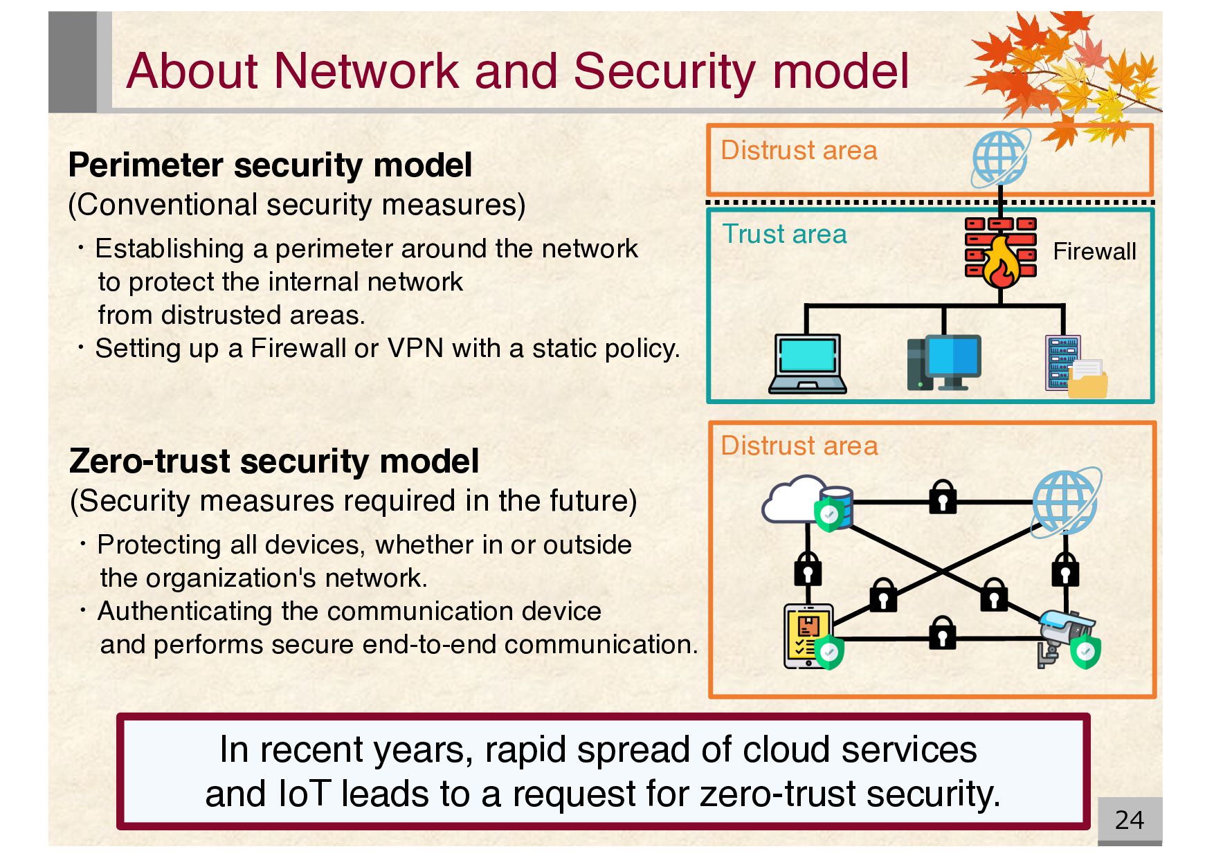
spread of cloud services and IoT leads to a request for zero-trust security. Perimeter security model (Conventional security measures) ・Establishing a perimeter around the network to protect the internal network from distrusted areas. ・Setting up a Firewall or VPN with a static policy. Zero-trust security model (Security measures required in the future) ・Protecting all devices, whether in or outside the organization's network. ・Authenticating the communication device and performs secure end-to-end communication. Firewall Distrust area Trust area Distrust area
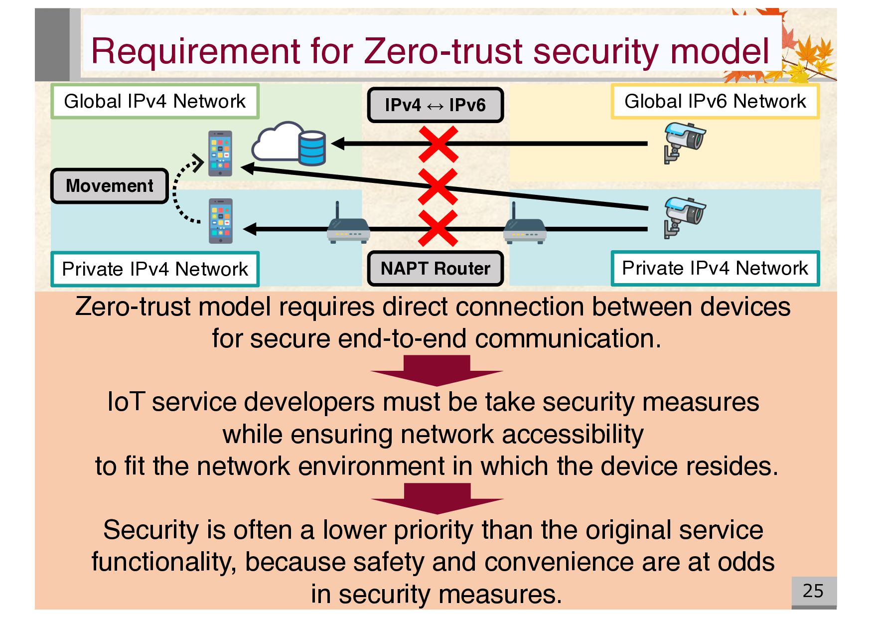
IPv4 Network Movement Private IPv4 Network Global IPv6 Network NAPT Router IPv4 ↔ IPv6 Zero-trust model requires direct connection between devices for secure end-to-end communication. IoT service developers must be take security measures while ensuring network accessibility to fit the network environment in which the device resides. Security is often a lower priority than the original service functionality, because safety and convenience are at odds in security measures.
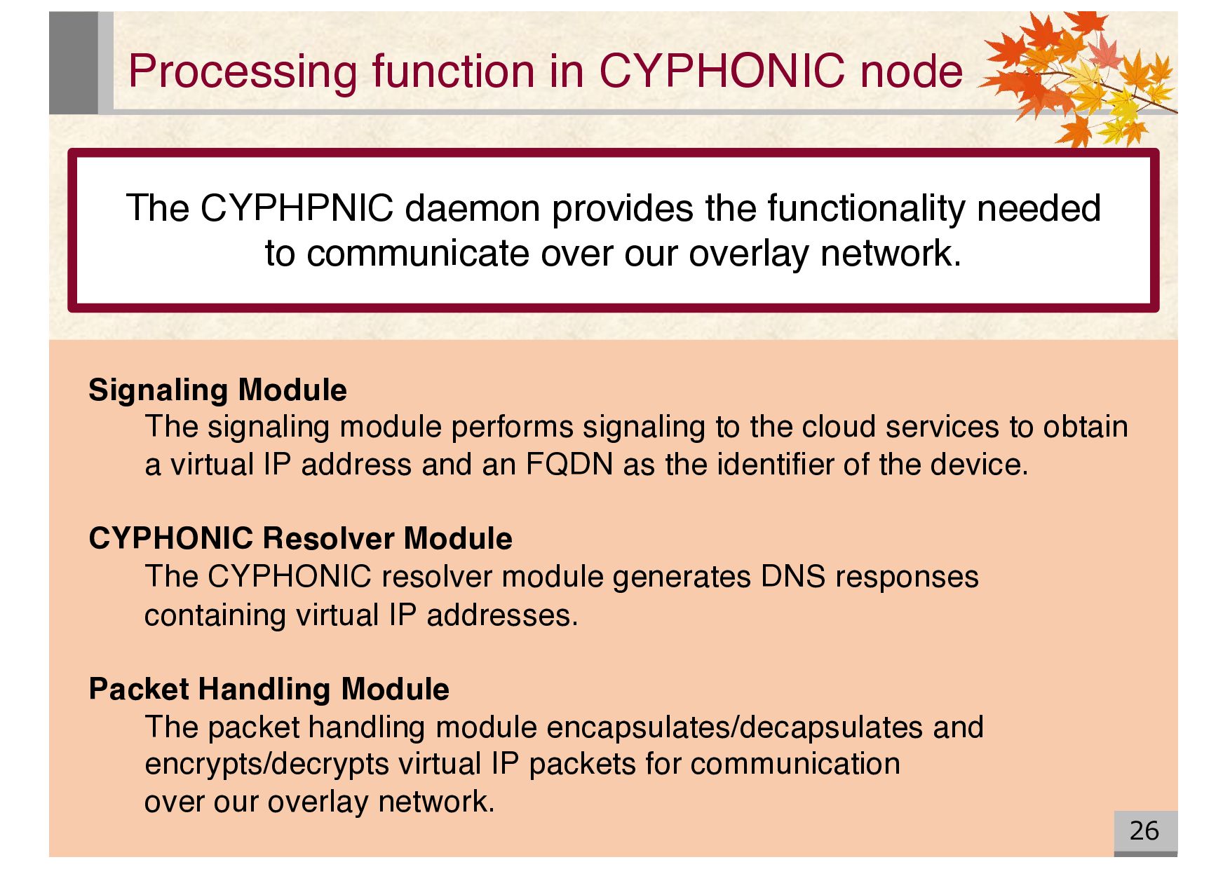
the functionality needed to communicate over our overlay network. Signaling Module The signaling module performs signaling to the cloud services to obtain a virtual IP address and an FQDN as the identifier of the device. CYPHONIC Resolver Module The CYPHONIC resolver module generates DNS responses containing virtual IP addresses. Packet Handling Module The packet handling module encapsulates/decapsulates and encrypts/decrypts virtual IP packets for communication over our overlay network.
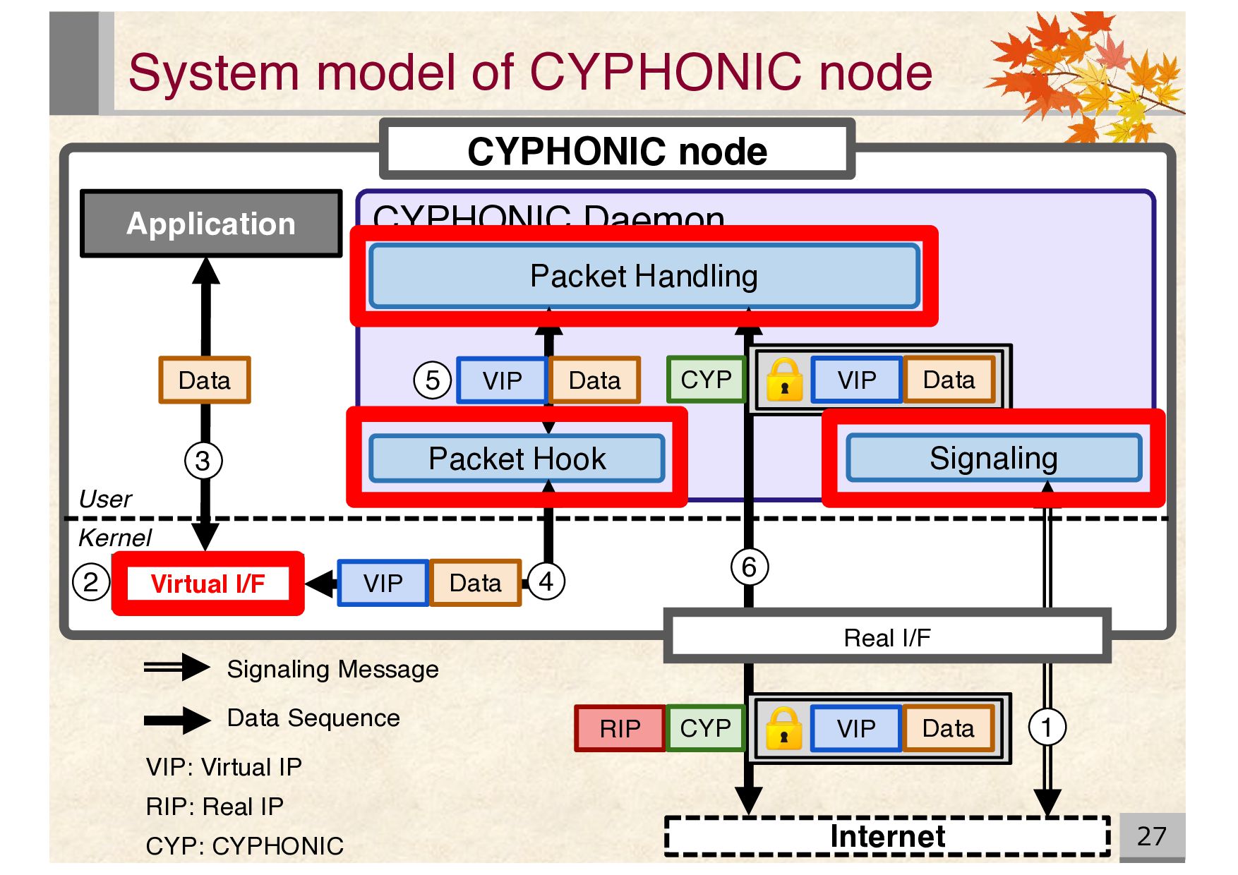
Real IP CYP: CYPHONIC Signaling Message Data Sequence CYPHONIC node Virtual I/F Internet CYPHONIC Daemon Application Packet Handling CYP VIP Data RIP CYP VIP Data Packet Hook VIP Data Kernel User Data VIP Data 6 2 3 4 5 Signaling 1 Real I/F
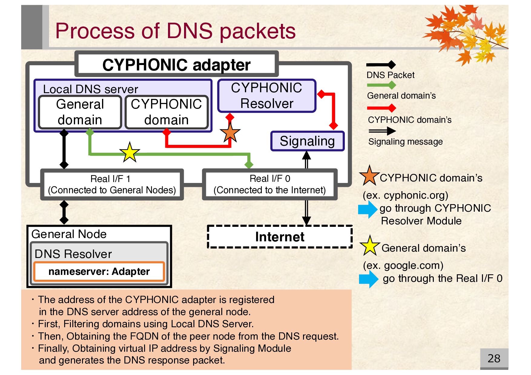
CYPHONIC domain’s (ex. cyphonic.org) go through CYPHONIC Resolver Module Process of DNS packets 28 CYPHONIC adapter CYPHONIC Resolver Local DNS server General domain CYPHONIC domain Signaling Real I/F 1 (Connected to General Nodes) nameserver: Adapter General Node DNS Resolver Internet ・The address of the CYPHONIC adapter is registered in the DNS server address of the general node. ・First, Filtering domains using Local DNS Server. ・Then, Obtaining the FQDN of the peer node from the DNS request. ・Finally, Obtaining virtual IP address by Signaling Module and generates the DNS response packet. Real I/F 0 (Connected to the Internet) Signaling message CYPHONIC domain’s DNS Packet General domain’s
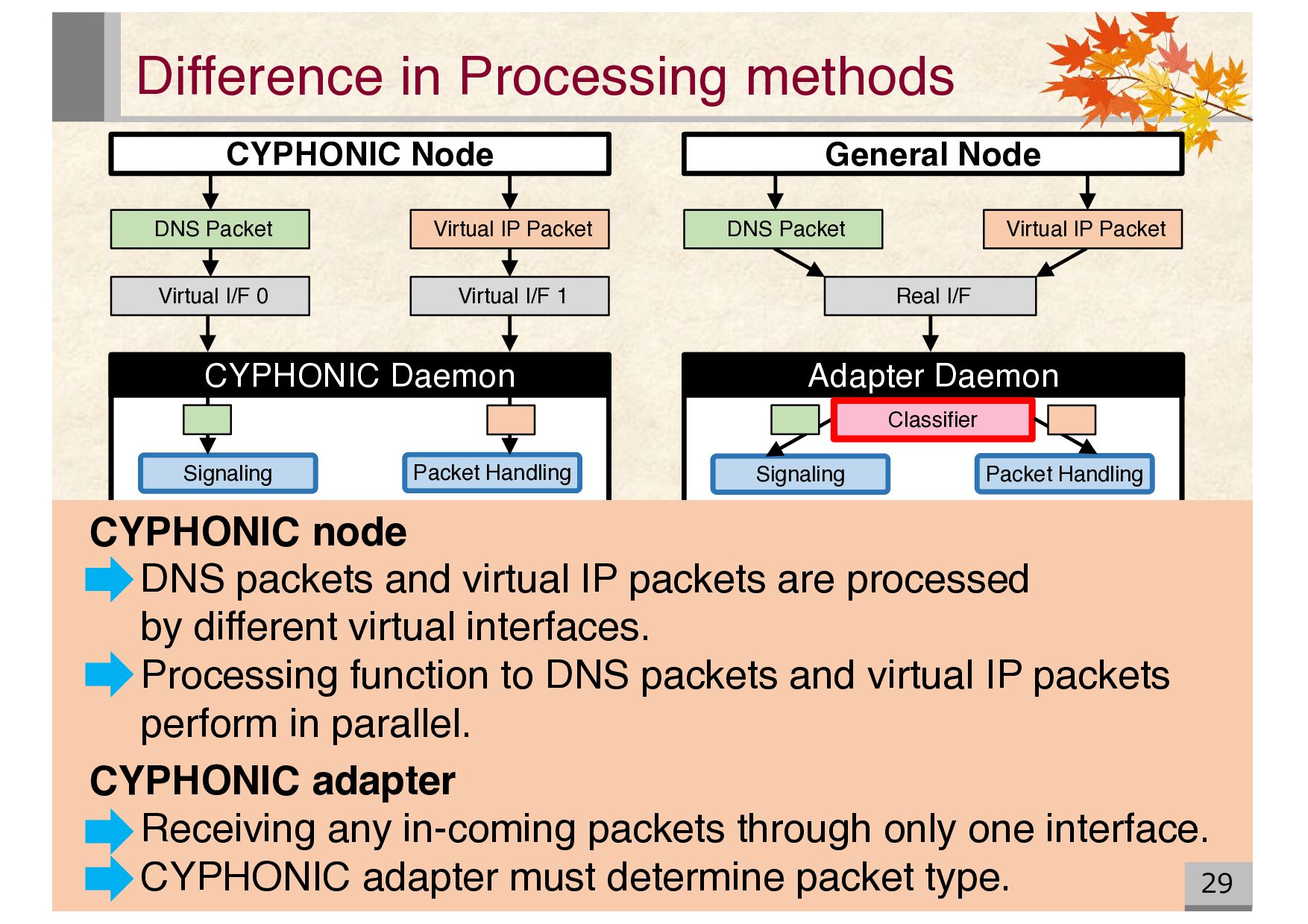
packets and virtual IP packets are processed by different virtual interfaces. Processing function to DNS packets and virtual IP packets perform in parallel. CYPHONIC adapter Receiving any in-coming packets through only one interface. CYPHONIC adapter must determine packet type. CYPHONIC Node General Node Virtual IP Packet DNS Packet Virtual I/F 0 Virtual I/F 1 Real I/F Signaling Signaling Packet Handling CYPHONIC Daemon Adapter Daemon DNS Packet Virtual IP Packet Classifier
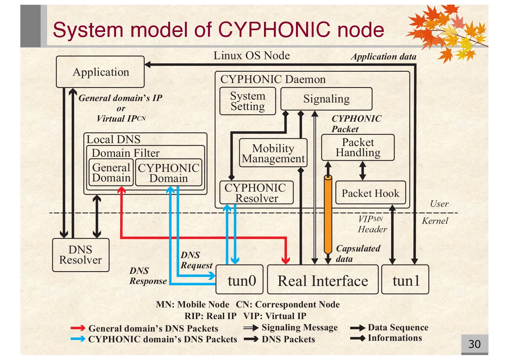
CYPHONIC Daemon CYPHONIC Packet General domain’s IP or Virtual IPCN Mobility Management System Setting CYPHONIC Resolver General Domain CYPHONIC Domain Domain Filter Local DNS Linux OS Node DNS Response User Kernel VIPMN Header DNS Request DNS Resolver Application CN: Correspondent Node MN: Mobile Node tun0 Application data tun1 Real Interface Informations CYPHONIC domain’s DNS Packets General domain’ s DNS Packets DNS Packets Data Sequence Signaling Message RIP: Real IP VIP: Virtual IP Capsulated data 30
Virtual IP Adapter Function Interface Handling General Node Management General Node Information Address Configuration Real Interface (eth1) DNS Response Connected to General Nodes User Kernel DHCPv4 Process DNS Request Real Interface (eth0) Connected to the Internet Informations CYPHONIC domain’s DNS Packets Data Sequence Signaling Message General Node Configuration VIPCN CYPHONIC Resolver Packet Handling Signaling CYPHONIC Daemon Application data Signaling data Capsulated data CYPHONIC Packet src: RIP dst: RIP Adapter CN src: VIP dst: VIPCN GN 31 System model of conventional CYPHONIC adapter
Configuration Address Configuration Router Configuration Interface Handling General Node Management CYPHONIC Resolver Signaling Packet Handling DNS Information General Node Information CYPHONIC Packet Connected to General nodes Real Interface (eth1) Connected to the Internet Real Interface (eth0) Signaling data Adapter Daemon Kernel Stateful DHCPv6 Process DNS Req. DNS Res. General Node Configuration CYPHONIC domain’s DNS Packets General domain’ s DNS Packets DNS Packets Data Sequence Informations Signaling Message Application data src: VIP dst: VIP GN CN User CN: Correspondent Node GN: General Node RIP: Real IP VIP: Virtual IP VIPCN Capsulated data src: RIP dst: RIP Adapter CN 32
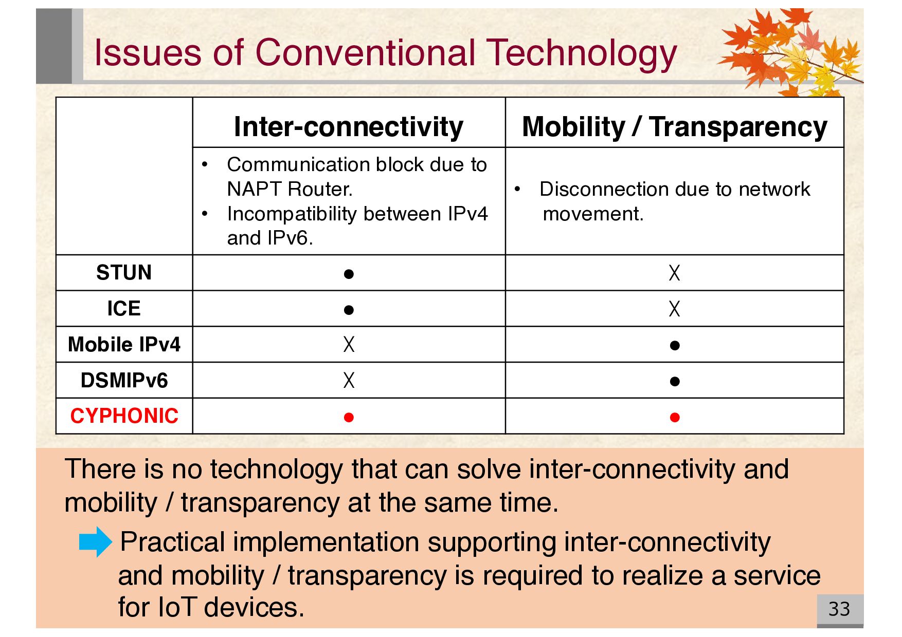
Communication block due to NAPT Router. • Incompatibility between IPv4 and IPv6. • Disconnection due to network movement. STUN • ☓ ICE • ☓ Mobile IPv4 ☓ • DSMIPv6 ☓ • CYPHONIC • • There is no technology that can solve inter-connectivity and mobility / transparency at the same time. Practical implementation supporting inter-connectivity and mobility / transparency is required to realize a service for IoT devices.
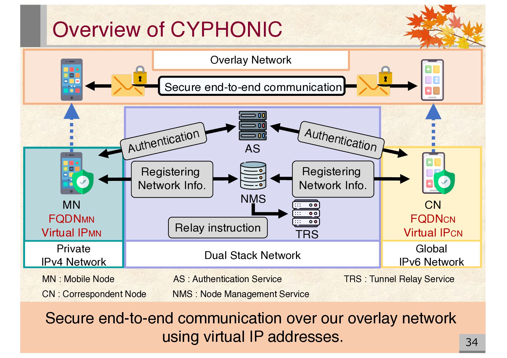
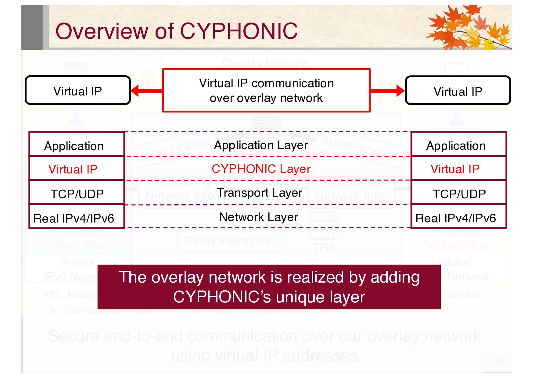
Correspondent Node NMS : Node Management Service AS : Authentication Service TRS : Tunnel Relay Service Private IPv4 Network Dual Stack Network AS NMS TRS MN CN FQDNMN Virtual IPMN FQDNCN 仮想IPアドレス Overlay Network Secure end-to-end communication Global IPv6 Network CN FQDNCN Virtual IPCN Authentication Authentication Registering Network Info. Registering Network Info. Relay instruction Secure end-to-end communication over our overlay network using virtual IP addresses. CYPHIO The overlay network is realized by adding CYPHONIC’s unique layer Application Real IPv4/IPv6 Virtual IP TCP/UDP Application Real IPv4/IPv6 Virtual IP TCP/UDP CYPHONIC Layer Application Layer Transport Layer Network Layer Virtual IP Virtual IP communication over overlay network Virtual IP
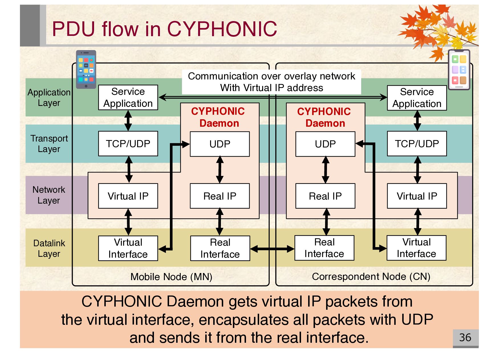
Real Interface Real IP UDP UDP Real IP Virtual IP Real Interface Virtual Interface TCP/UDP Service Application Communication over overlay network With Virtual IP address Virtual IP CYPHONIC Daemon CYPHONIC Daemon Mobile Node (MN) Correspondent Node (CN) Application Layer Transport Layer Network Layer Datalink Layer CYPHONIC Daemon gets virtual IP packets from the virtual interface, encapsulates all packets with UDP and sends it from the real interface.
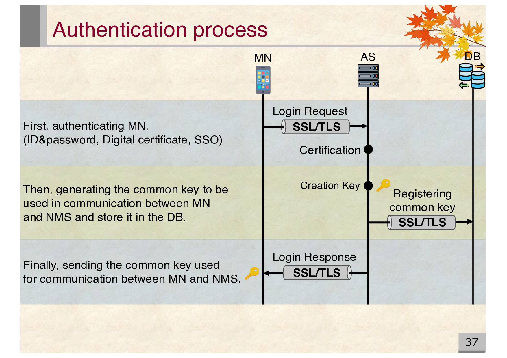
Login Request Login Response SSL/TLS SSL/TLS AS MN DB First, authenticating MN. (ID&password, Digital certificate, SSO) Then, generating the common key to be used in communication between MN and NMS and store it in the DB. Finally, sending the common key used for communication between MN and NMS.
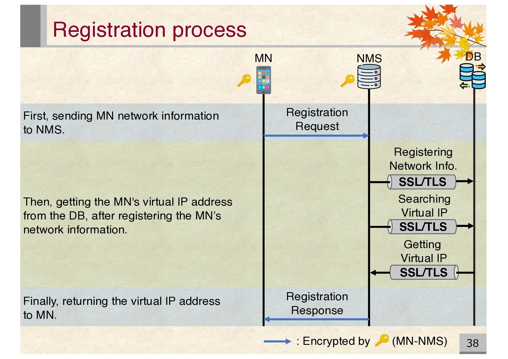
Searching Virtual IP SSL/TLS Getting Virtual IP NMS Registration Request Registration Response : Encrypted by (MN-NMS) First, sending MN network information to NMS. Then, getting the MN's virtual IP address from the DB, after registering the MN’s network information. Finally, returning the virtual IP address to MN.
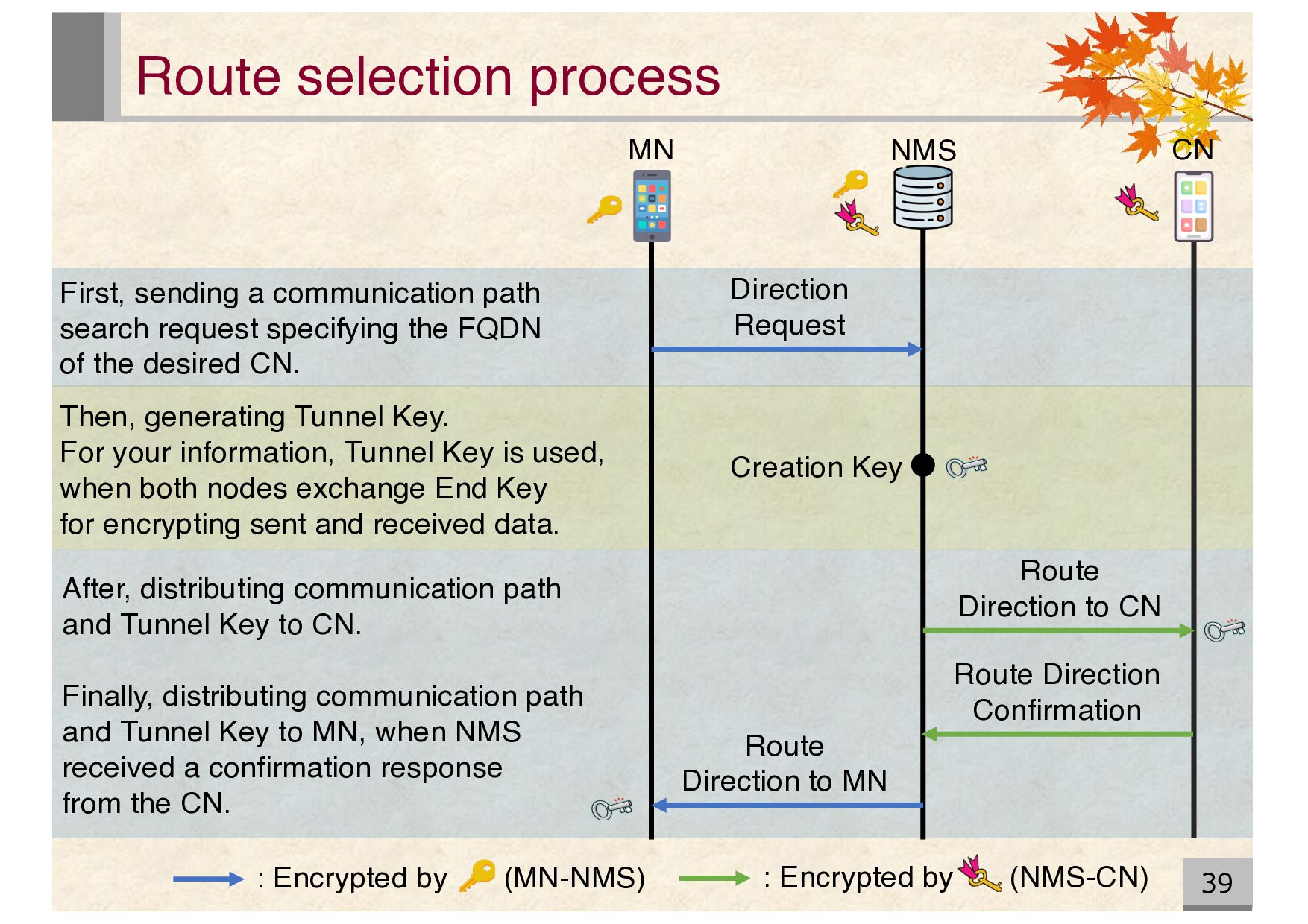
CN Direction Request Route Direction to MN Creation Key Route Direction to CN Route Direction Confirmation : Encrypted by (MN-NMS) Then, generating Tunnel Key. For your information, Tunnel Key is used, when both nodes exchange End Key for encrypting sent and received data. First, sending a communication path search request specifying the FQDN of the desired CN. After, distributing communication path and Tunnel Key to CN. Finally, distributing communication path and Tunnel Key to MN, when NMS received a confirmation response from the CN.
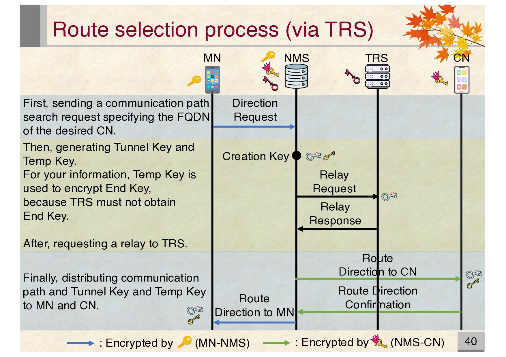
Direction to MN Creation Key Route Direction Confirmation TRS Direction Request Relay Request Relay Response Route Direction to CN : Encrypted by (MN-NMS) : Encrypted by (NMS-CN) First, sending a communication path search request specifying the FQDN of the desired CN. Then, generating Tunnel Key and Temp Key. For your information, Temp Key is used to encrypt End Key, because TRS must not obtain End Key. After, requesting a relay to TRS. Finally, distributing communication path and Tunnel Key and Temp Key to MN and CN.
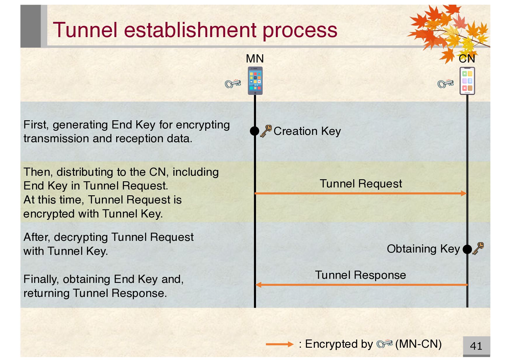
Tunnel Response : Encrypted by (MN-CN) Obtaining Key After, decrypting Tunnel Request with Tunnel Key. Finally, obtaining End Key and, returning Tunnel Response. Then, distributing to the CN, including End Key in Tunnel Request. At this time, Tunnel Request is encrypted with Tunnel Key. First, generating End Key for encrypting transmission and reception data.
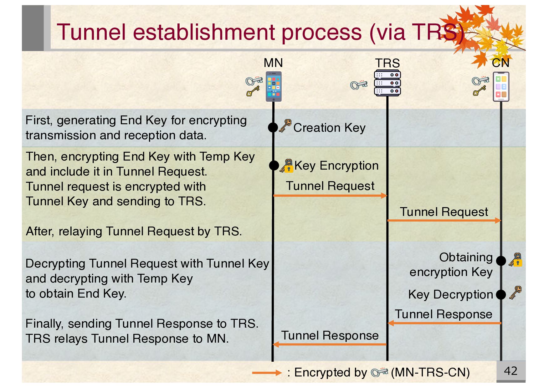
Key Key Encryption Tunnel Request Tunnel Request Key Decryption Tunnel Response Tunnel Response Obtaining encryption Key : Encrypted by (MN-TRS-CN) Decrypting Tunnel Request with Tunnel Key and decrypting with Temp Key to obtain End Key. Finally, sending Tunnel Response to TRS. TRS relays Tunnel Response to MN. Then, encrypting End Key with Temp Key and include it in Tunnel Request. Tunnel request is encrypted with Tunnel Key and sending to TRS. After, relaying Tunnel Request by TRS. First, generating End Key for encrypting transmission and reception data.