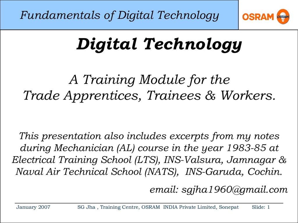
Centre, OSRAM INDIA Private Limited, Sonepat Slide: 1 Digital Technology A Training Module for the Trade Apprentices, Trainees & Workers. This presentation also includes excerpts from my notes during Mechanician (AL) course in the year 1983-85 at Electrical Training School (LTS), INS-Valsura, Jamnagar & Naval Air Technical School (NATS), INS-Garuda, Cochin. email: [email protected]
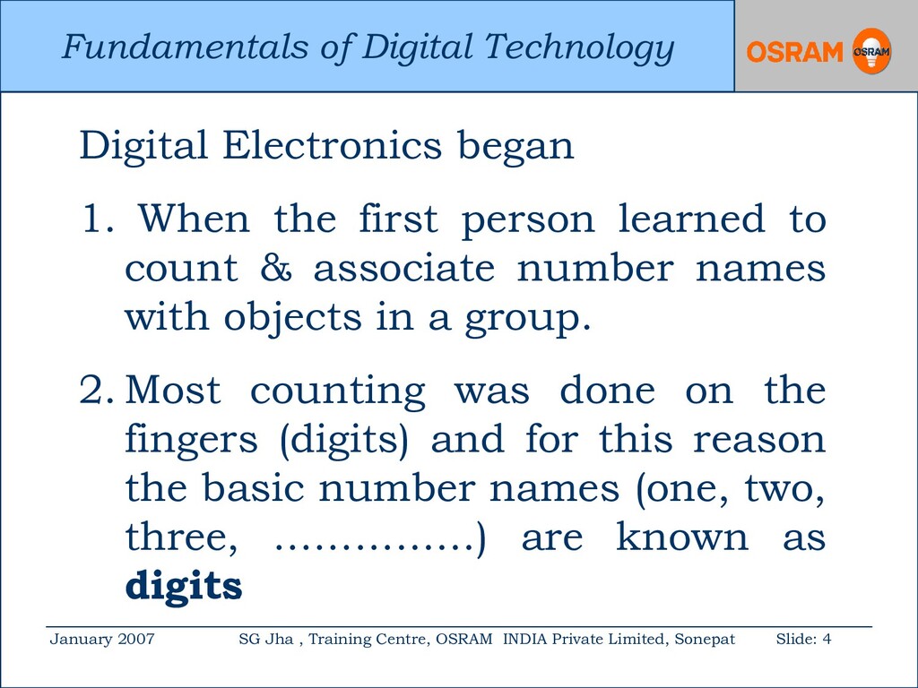
Centre, OSRAM INDIA Private Limited, Sonepat Slide: 4 Digital Electronics began 1. When the first person learned to count & associate number names with objects in a group. 2. Most counting was done on the fingers (digits) and for this reason the basic number names (one, two, three, ……………) are known as digits .
Centre, OSRAM INDIA Private Limited, Sonepat Slide: 5 The invention of numbers led to arithmetic and all kinds of calculating devices. The really crucial inventions in the evolution of digital electronics were made in the nineteenth century.
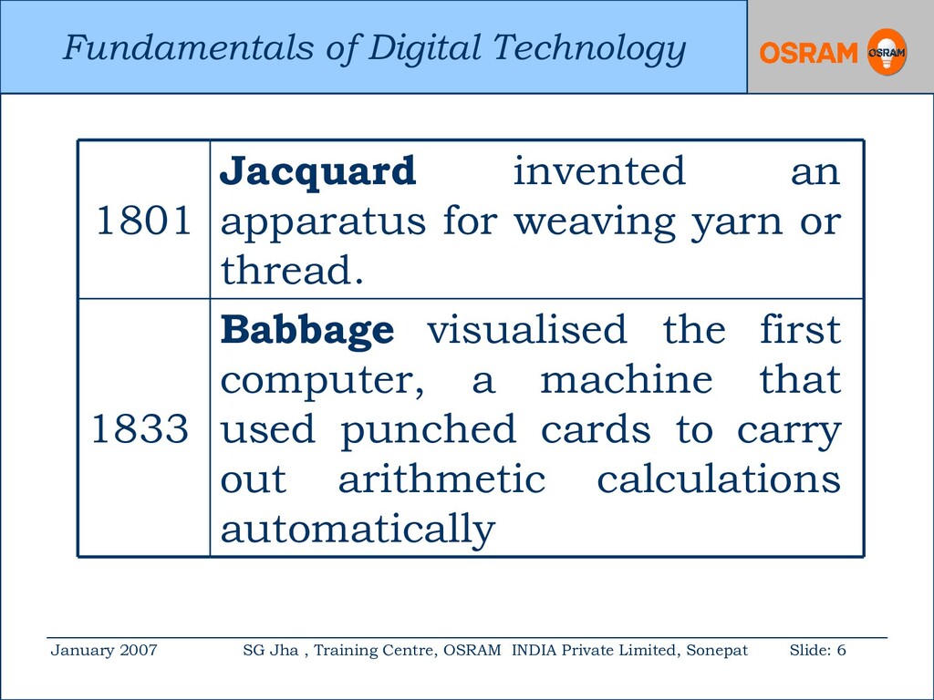
Centre, OSRAM INDIA Private Limited, Sonepat Slide: 6 1801 Jacquard invented an apparatus for weaving yarn or thread. 1833 Babbage visualised the first computer, a machine that used punched cards to carry out arithmetic calculations automatically
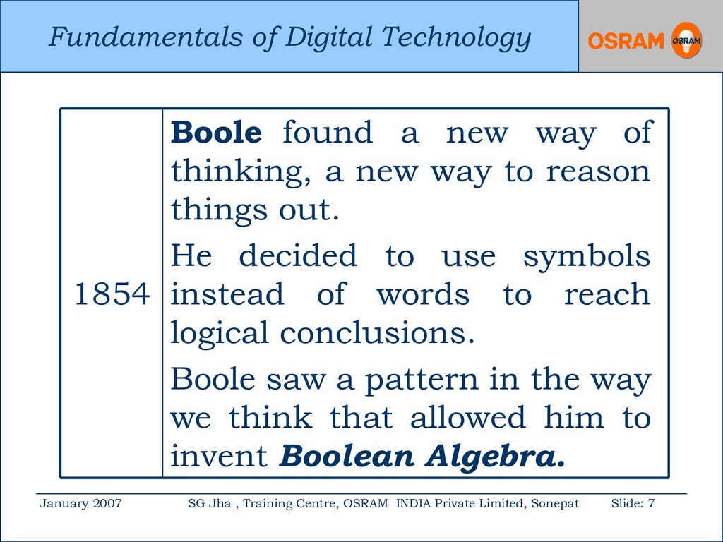
Centre, OSRAM INDIA Private Limited, Sonepat Slide: 7 1854 Boole found a new way of thinking, a new way to reason things out. He decided to use symbols instead of words to reach logical conclusions. Boole saw a pattern in the way we think that allowed him to invent Boolean Algebra.
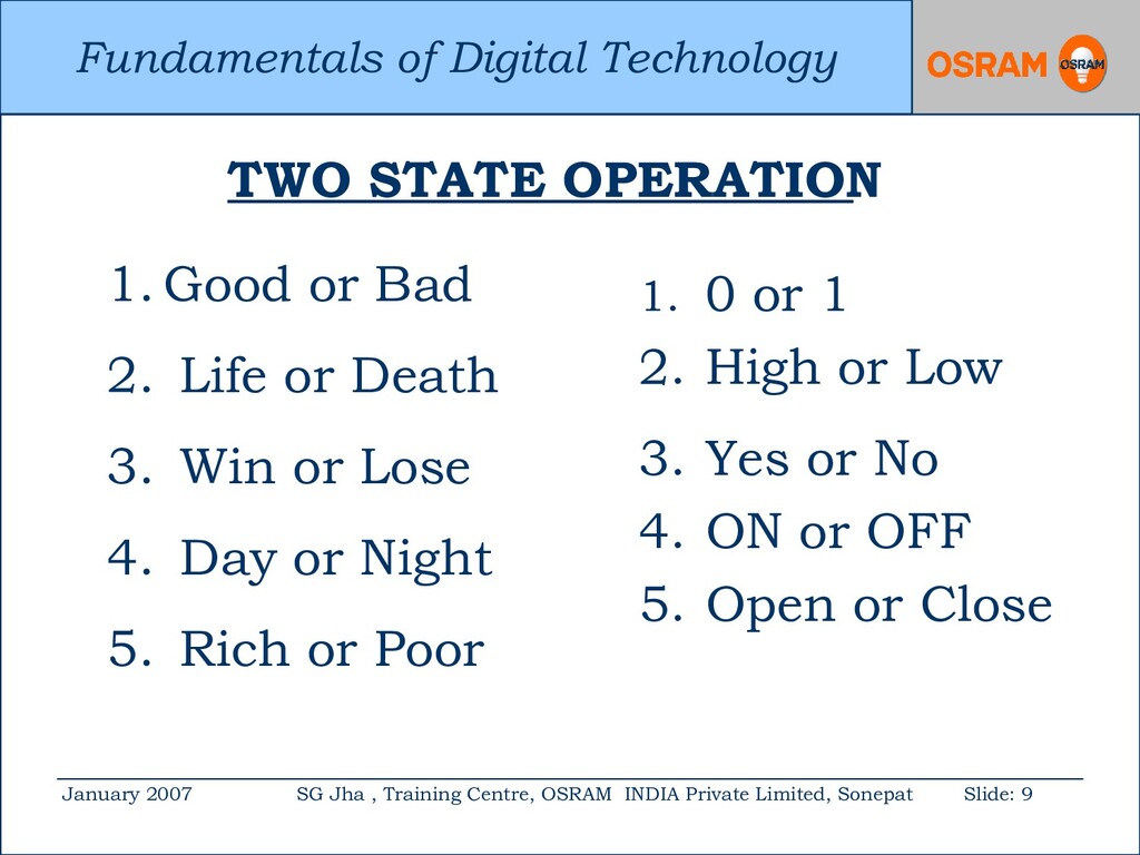
Centre, OSRAM INDIA Private Limited, Sonepat Slide: 9 1. Good or Bad 2. Life or Death 3. Win or Lose 4. Day or Night 5. Rich or Poor 1. 0 or 1 2. High or Low 3. Yes or No 4. ON or OFF 5. Open or Close TWO STATE OPERATION
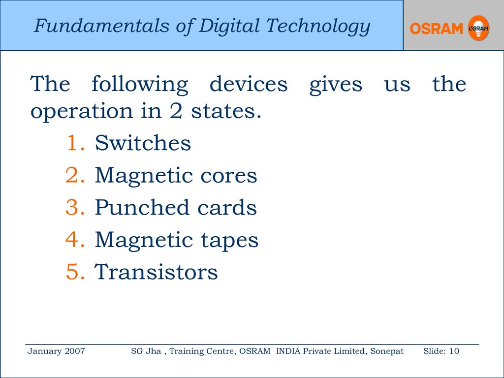
Centre, OSRAM INDIA Private Limited, Sonepat Slide: 10 The following devices gives us the operation in 2 states. 1. Switches 2. Magnetic cores 3. Punched cards 4. Magnetic tapes 5. Transistors
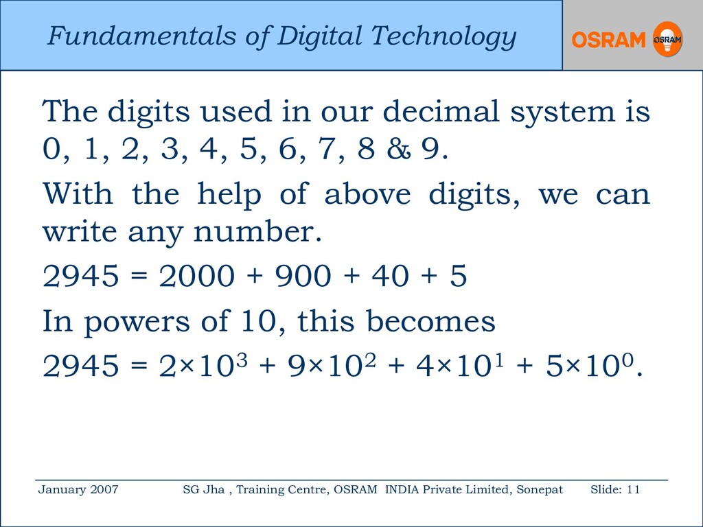
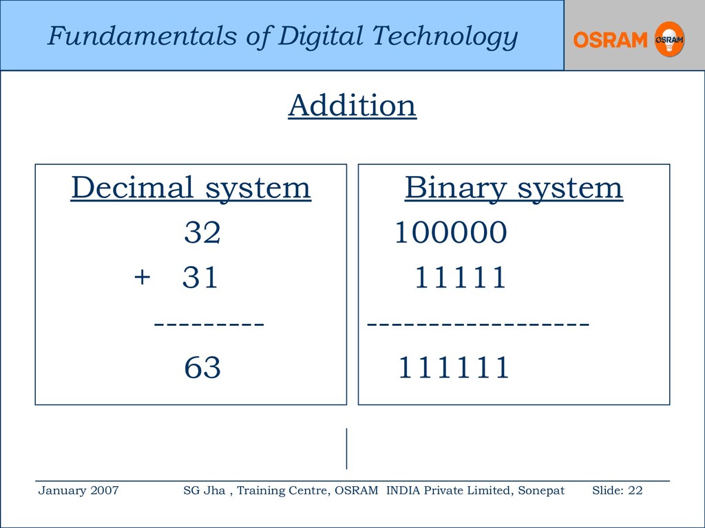
Centre, OSRAM INDIA Private Limited, Sonepat Slide: 11 The digits used in our decimal system is 0, 1, 2, 3, 4, 5, 6, 7, 8 & 9. With the help of above digits, we can write any number. 2945 = 2000 + 900 + 40 + 5 In powers of 10, this becomes 2945 = 2×10³ + 9×10² + 4×101 + 5×100.
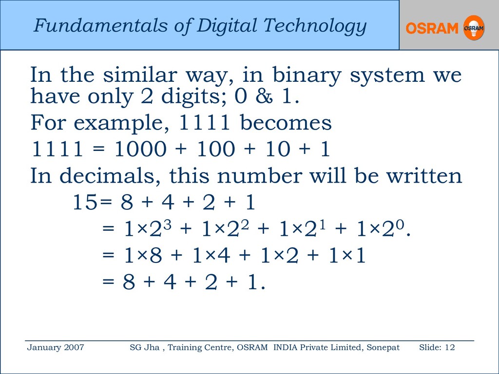
Centre, OSRAM INDIA Private Limited, Sonepat Slide: 12 In the similar way, in binary system we have only 2 digits; 0 & 1. For example, 1111 becomes 1111 = 1000 + 100 + 10 + 1 In decimals, this number will be written 15= 8 + 4 + 2 + 1 = 1×23 + 1×22 + 1×21 + 1×20. = 1×8 + 1×4 + 1×2 + 1×1 = 8 + 4 + 2 + 1.
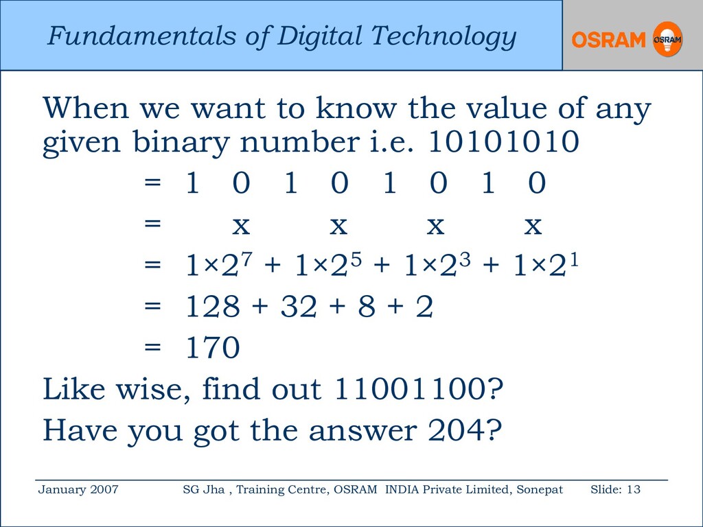
Centre, OSRAM INDIA Private Limited, Sonepat Slide: 13 When we want to know the value of any given binary number i.e. 10101010 = 1 0 1 0 1 0 1 0 = x x x x = 1×27 + 1×25 + 1×23 + 1×21 = 128 + 32 + 8 + 2 = 170 Like wise, find out 11001100? Have you got the answer 204?
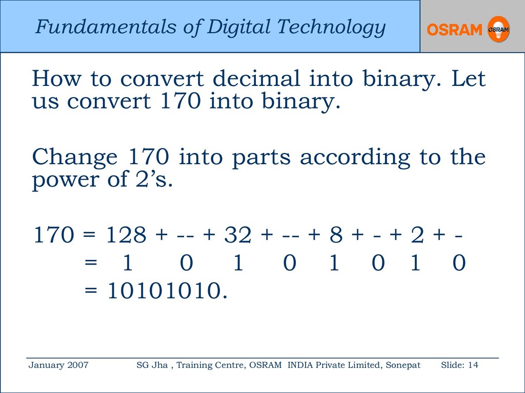
Centre, OSRAM INDIA Private Limited, Sonepat Slide: 14 How to convert decimal into binary. Let us convert 170 into binary. Change 170 into parts according to the power of 2’s. 170 = 128 + -- + 32 + -- + 8 + - + 2 + - = 1 0 1 0 1 0 1 0 = 10101010.
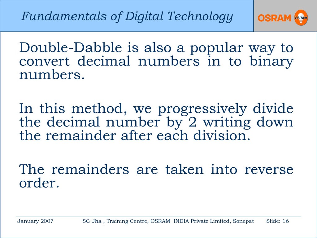
Centre, OSRAM INDIA Private Limited, Sonepat Slide: 16 Double-Dabble is also a popular way to convert decimal numbers in to binary numbers. In this method, we progressively divide the decimal number by 2 writing down the remainder after each division. The remainders are taken into reverse order.
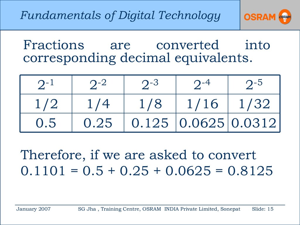
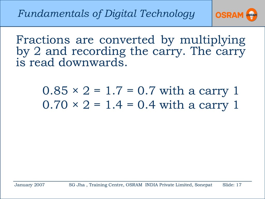
Centre, OSRAM INDIA Private Limited, Sonepat Slide: 17 Fractions are converted by multiplying by 2 and recording the carry. The carry is read downwards. 0.85 × 2 = 1.7 = 0.7 with a carry 1 0.70 × 2 = 1.4 = 0.4 with a carry 1
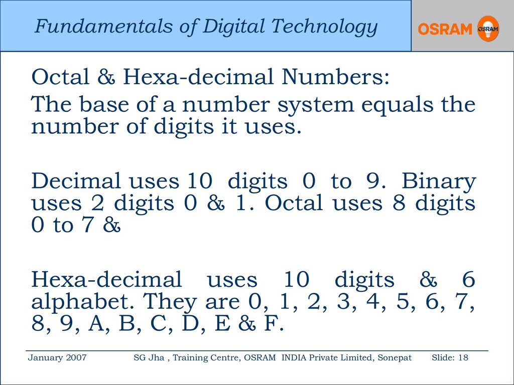
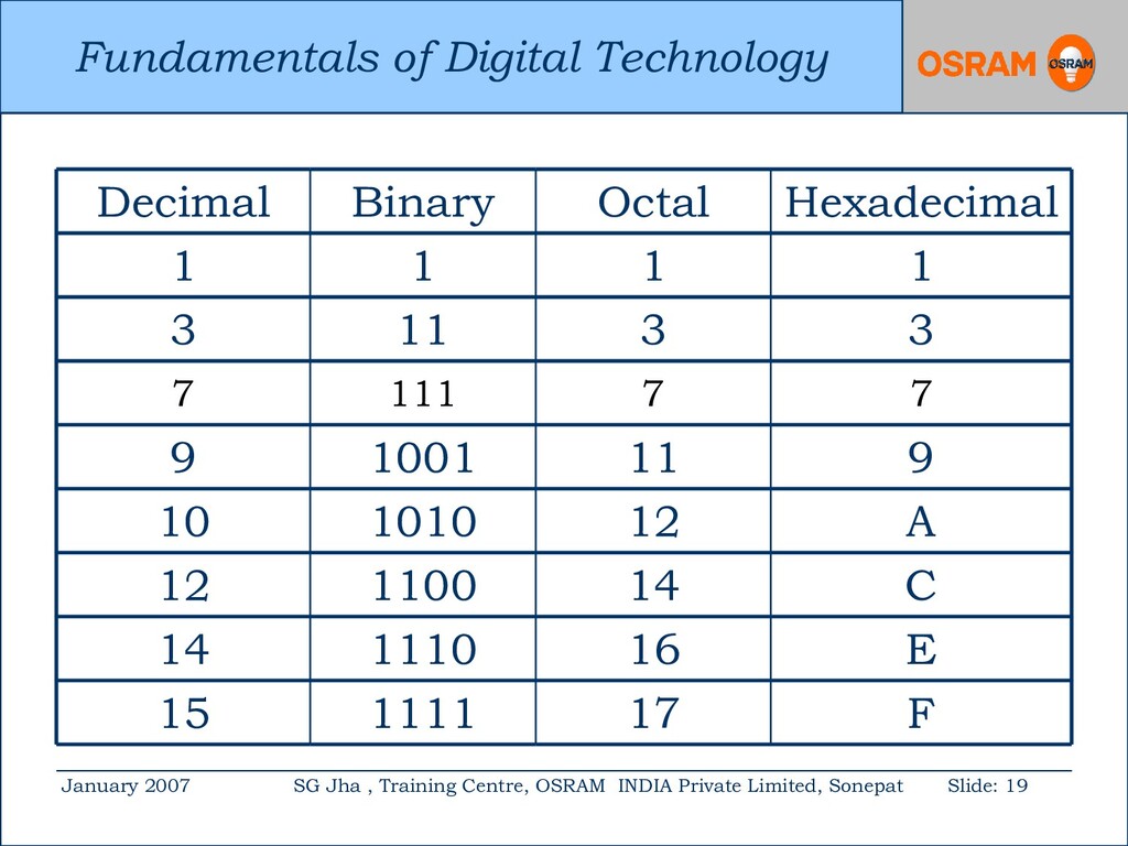
Centre, OSRAM INDIA Private Limited, Sonepat Slide: 18 Octal & Hexa-decimal Numbers: The base of a number system equals the number of digits it uses. Decimal uses 10 digits 0 to 9. Binary uses 2 digits 0 & 1. Octal uses 8 digits 0 to 7 & Hexa-decimal uses 10 digits & 6 alphabet. They are 0, 1, 2, 3, 4, 5, 6, 7, 8, 9, A, B, C, D, E & F.
Centre, OSRAM INDIA Private Limited, Sonepat Slide: 24 1’s & 2’s complement: 1’s complement is obtained by changing all 0’s to 1 and all 1’s to 0. 1’s complement of the following numbers 1010 = 0101 101100 = 010011 2’s complement = 1’s complement + 1
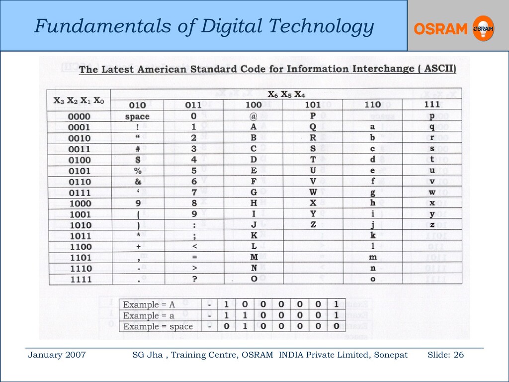
Centre, OSRAM INDIA Private Limited, Sonepat Slide: 25 Coding of numbers: The two coding schemes that are commonly used for data entry into digital computing systems are ASCII & HOLLERITH. ASCII code is used for encoding information. HOLLERITH is used in punched-card.
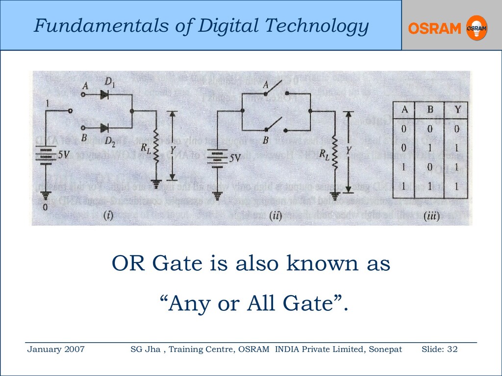
Centre, OSRAM INDIA Private Limited, Sonepat Slide: 31 OR Logic Gate While opening bank account with HDFC Bank, you mentioned in the form that “I OR my Wife” can withdraw money. One day, your wife goes to bank. Will the bank manager allow your wife to withdraw money?
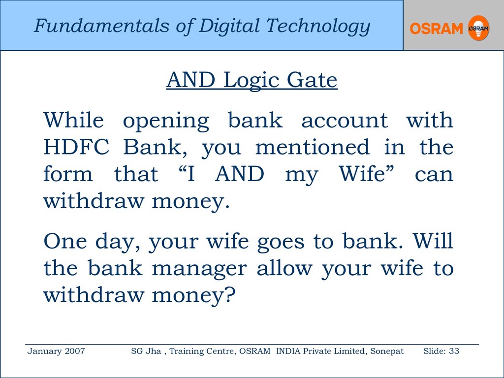
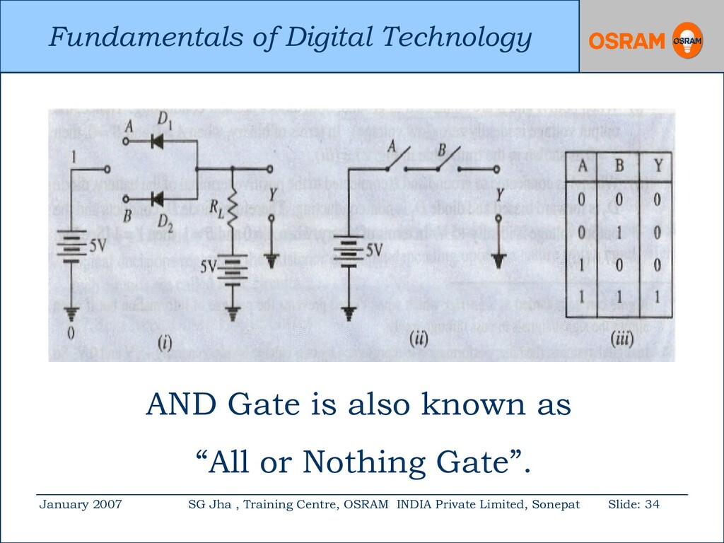
Centre, OSRAM INDIA Private Limited, Sonepat Slide: 33 AND Logic Gate While opening bank account with HDFC Bank, you mentioned in the form that “I AND my Wife” can withdraw money. One day, your wife goes to bank. Will the bank manager allow your wife to withdraw money?
Centre, OSRAM INDIA Private Limited, Sonepat Slide: 35 NOT Logic Gate The NOT gate or inverter is the simplest of all logic gates. It has only one input and one output.
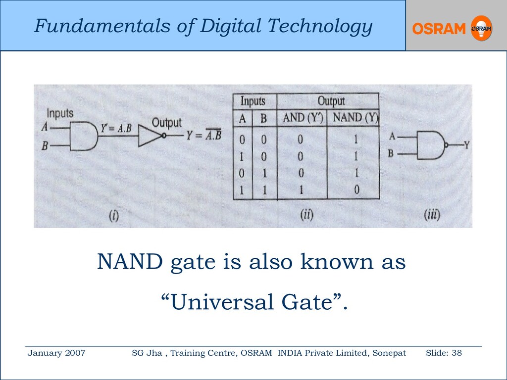
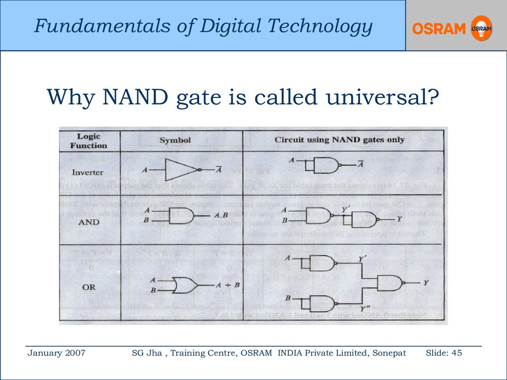
Centre, OSRAM INDIA Private Limited, Sonepat Slide: 37 NAND Logic Gate It is the combination of AND & NOT gate. In other words, the out put of the AND gate is connected to the input of the NOT gate. The little bubble on the right end of the symbol means to invert AND gate.
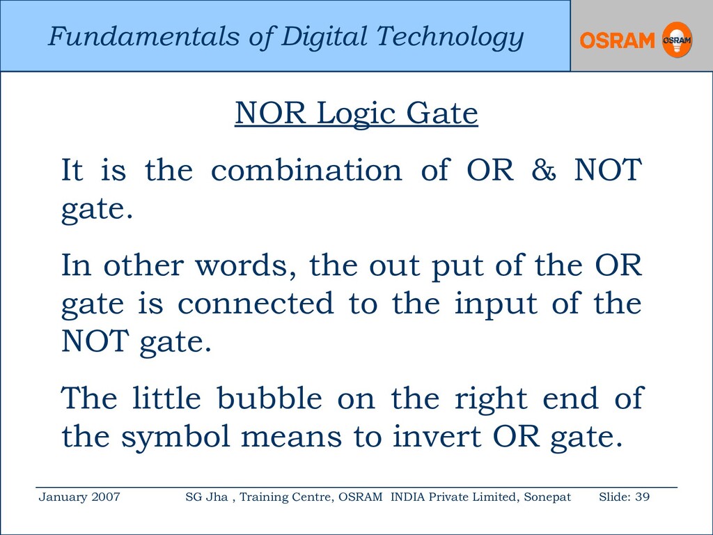
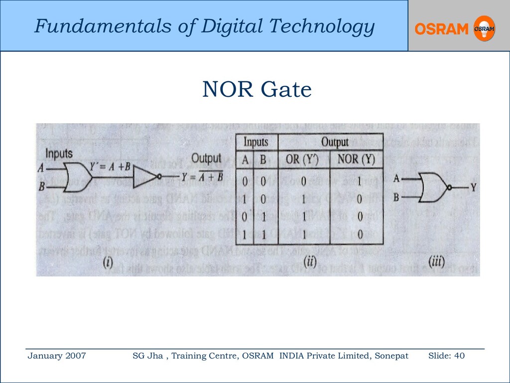
Centre, OSRAM INDIA Private Limited, Sonepat Slide: 39 NOR Logic Gate It is the combination of OR & NOT gate. In other words, the out put of the OR gate is connected to the input of the NOT gate. The little bubble on the right end of the symbol means to invert OR gate.
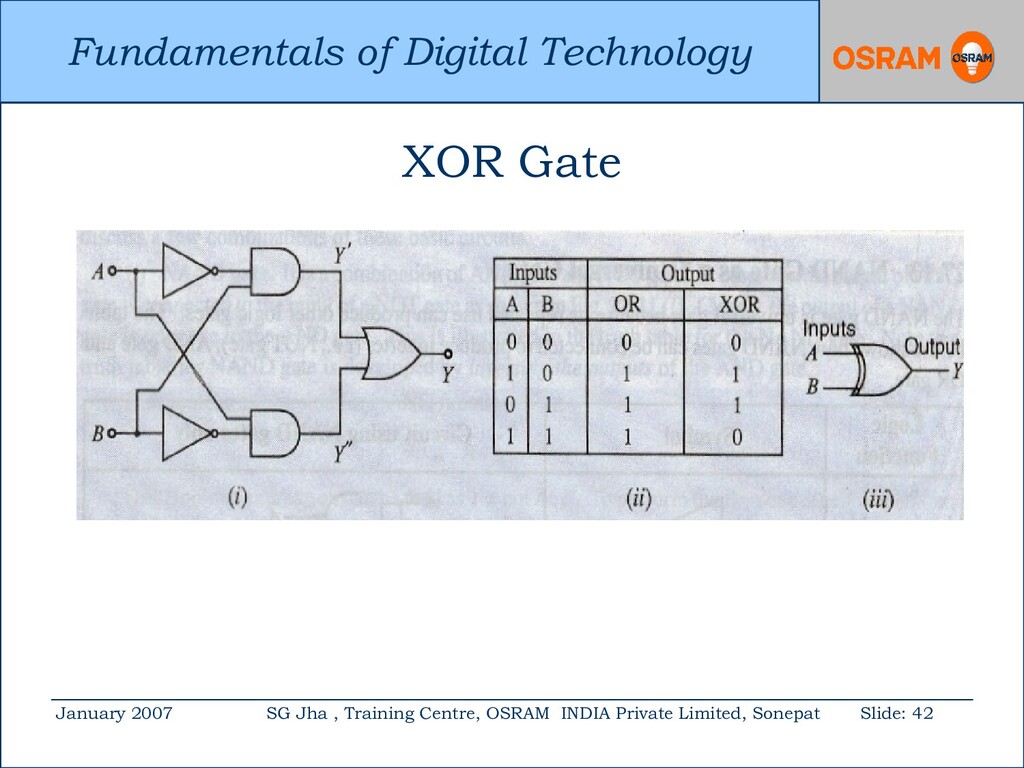
Centre, OSRAM INDIA Private Limited, Sonepat Slide: 41 Exclusive OR Logic Gate The name Exclusive OR gate is shortened to XOR. The XOR gate can be designed by combining OR, AND & NOT gates. Its exclusive feature is to give out put 0 when both inputs are 1.
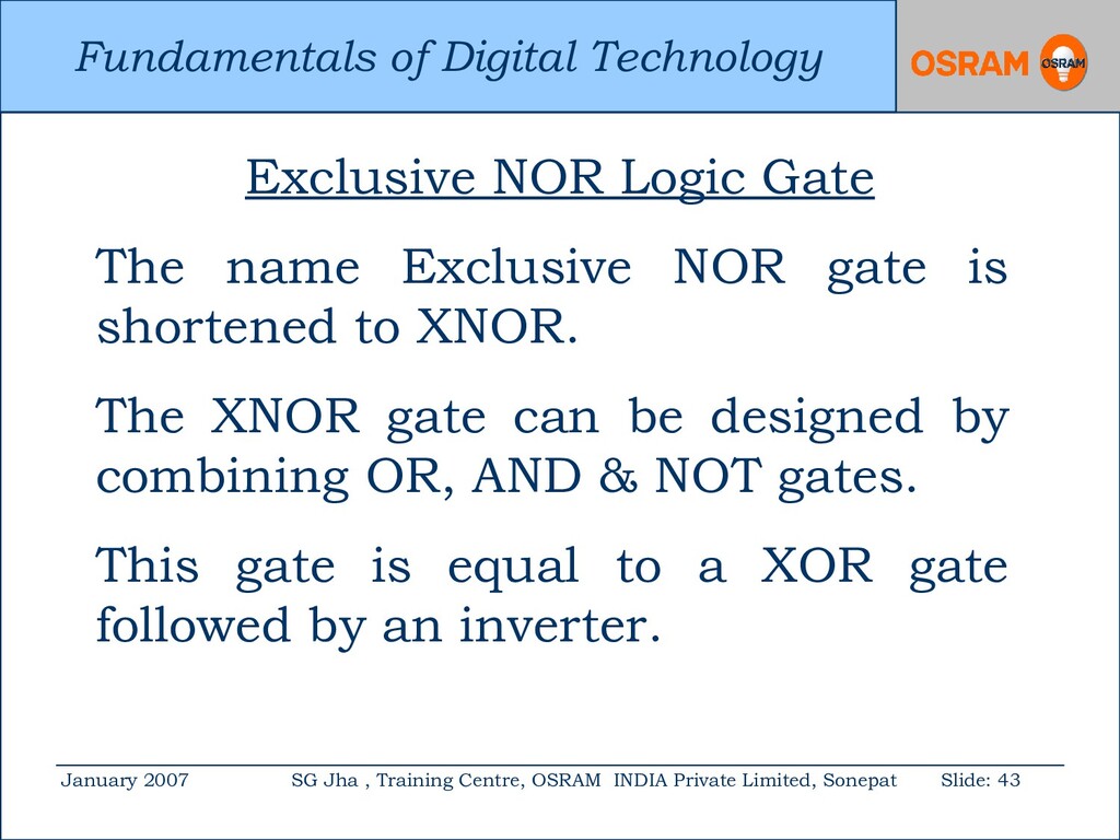
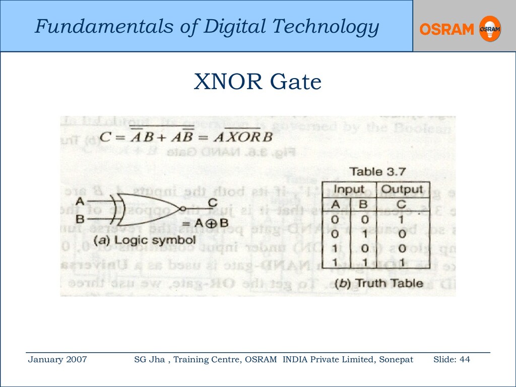
Centre, OSRAM INDIA Private Limited, Sonepat Slide: 43 Exclusive NOR Logic Gate The name Exclusive NOR gate is shortened to XNOR. The XNOR gate can be designed by combining OR, AND & NOT gates. This gate is equal to a XOR gate followed by an inverter.
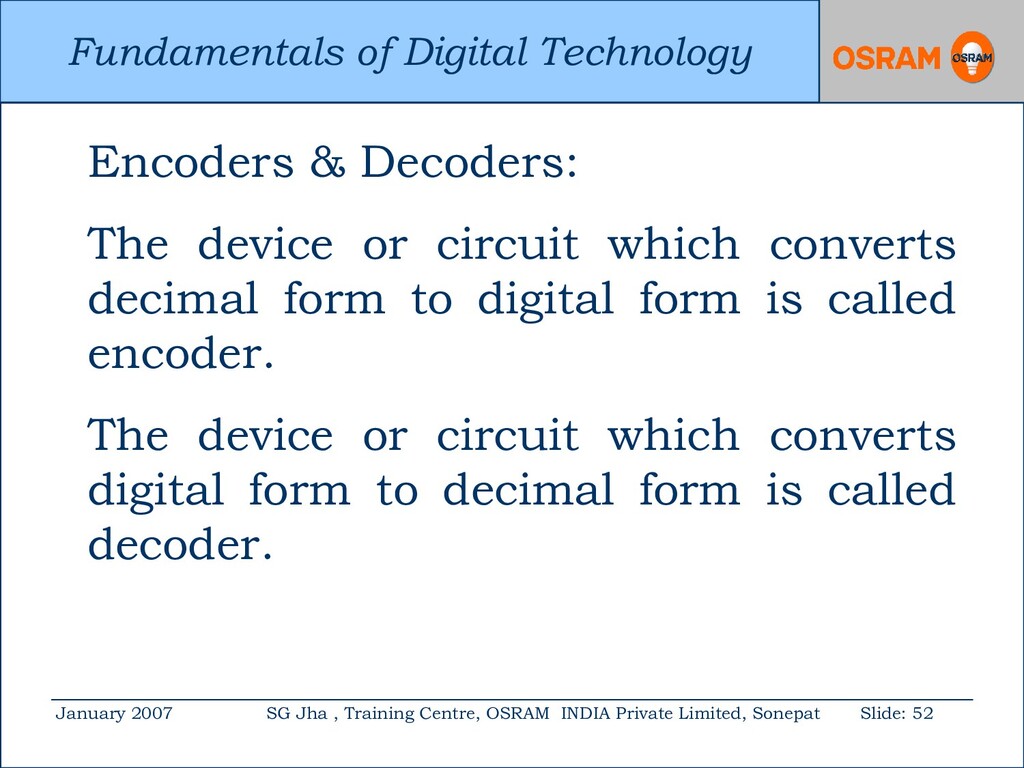
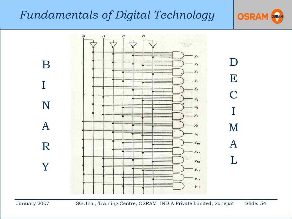
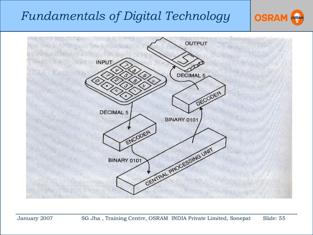
Centre, OSRAM INDIA Private Limited, Sonepat Slide: 52 Encoders & Decoders: The device or circuit which converts decimal form to digital form is called encoder. The device or circuit which converts digital form to decimal form is called decoder.
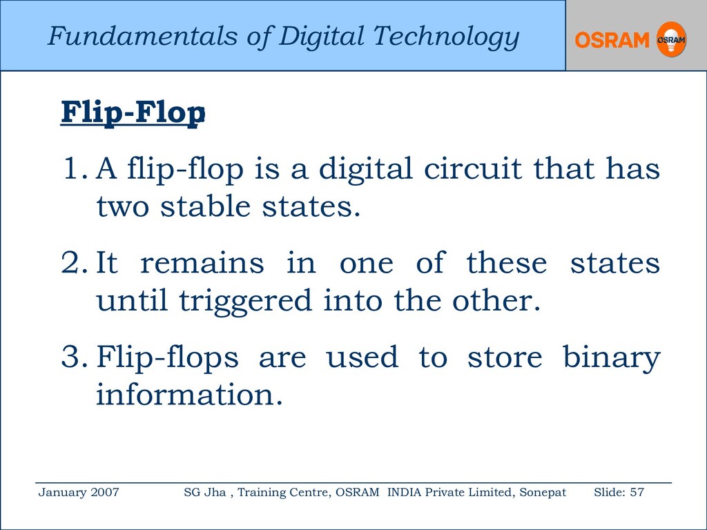
Centre, OSRAM INDIA Private Limited, Sonepat Slide: 57 Flip-Flop : 1. A flip-flop is a digital circuit that has two stable states. 2. It remains in one of these states until triggered into the other. 3. Flip-flops are used to store binary information.
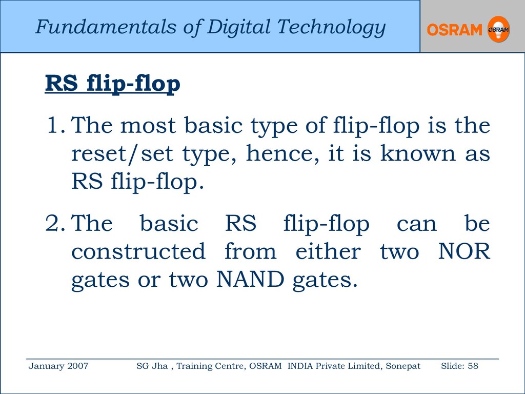
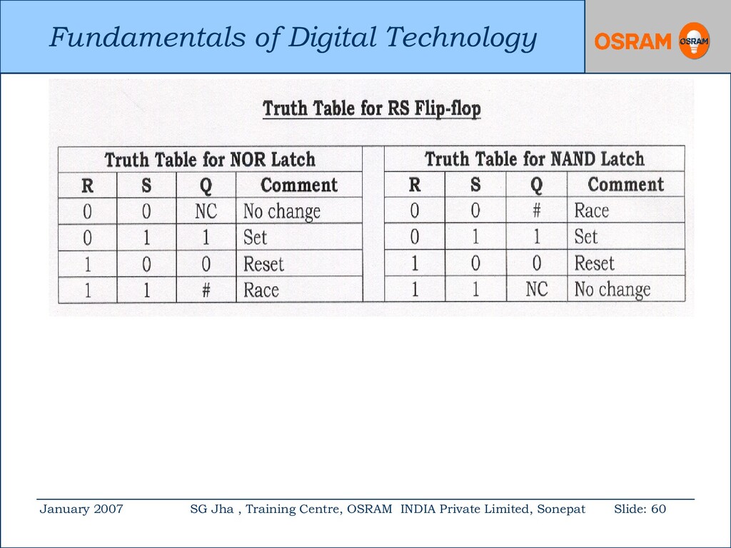
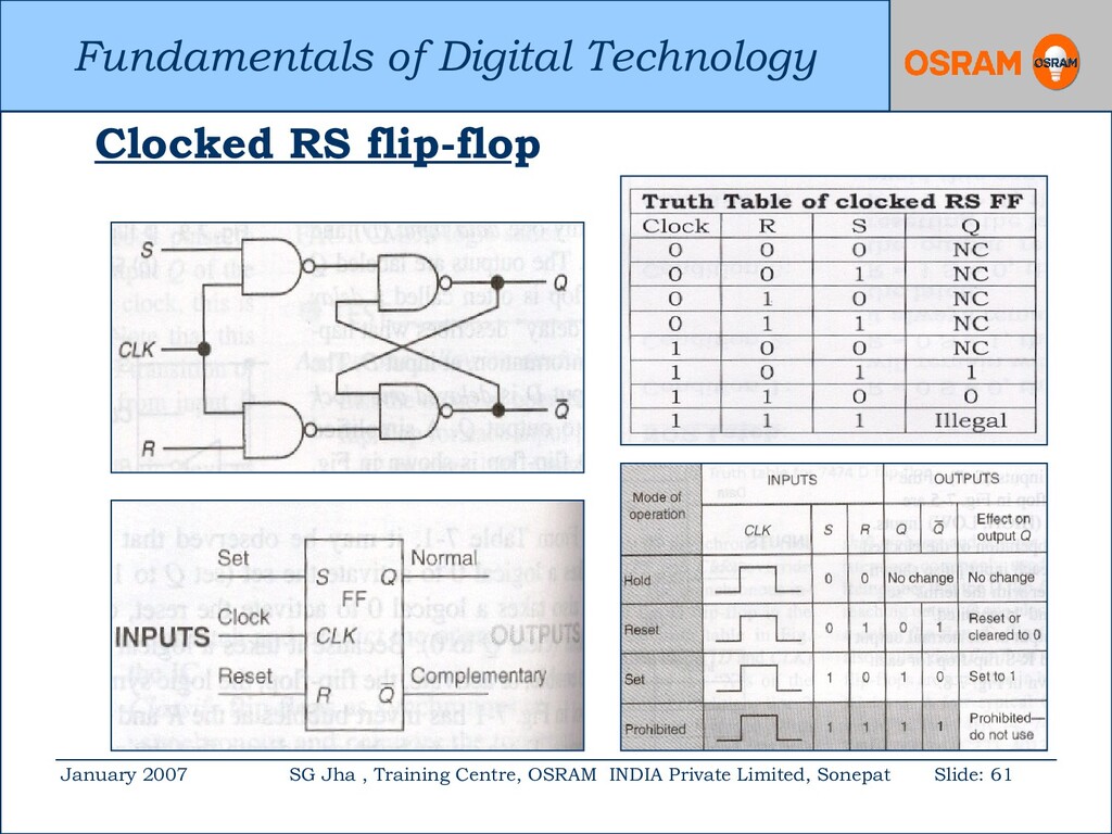
Centre, OSRAM INDIA Private Limited, Sonepat Slide: 58 RS flip-flop : 1. The most basic type of flip-flop is the reset/set type, hence, it is known as RS flip-flop. 2. The basic RS flip-flop can be constructed from either two NOR gates or two NAND gates.
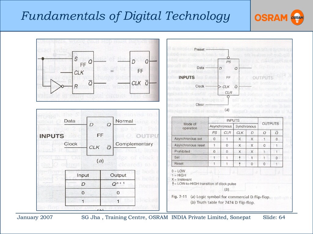
Centre, OSRAM INDIA Private Limited, Sonepat Slide: 62 D Flip-flop : 1. The RS flip-flop has two data inputs, R & S. 2. To store a high bit, we need a high S and to store a low bit, we need a high R. 3. Generations of two signals to drive a flip-flop is disadvantageous in many applications.
Centre, OSRAM INDIA Private Limited, Sonepat Slide: 63 4. Further more, the RS flip-flop is susceptible to a race condition. 5. To avoid racing condition, the RS flip -flop is modified and designed to eliminate the possibility of race condition. 6. This is called D flip-flop and has single input. 7. This is also known as delay flip-flop.
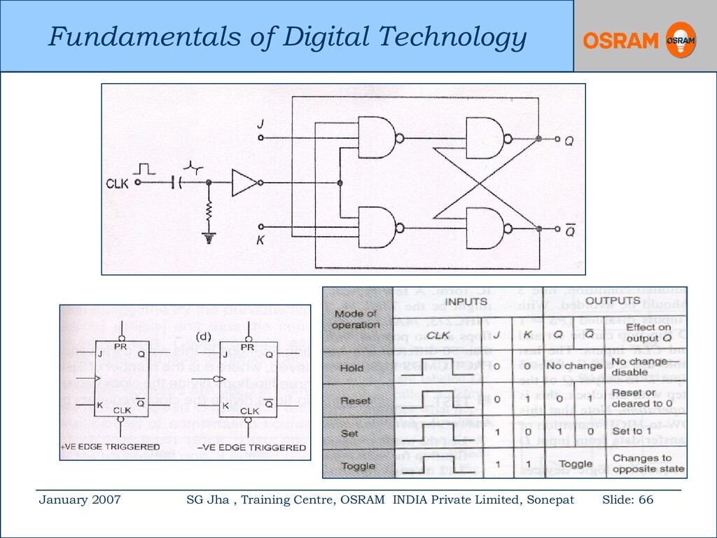
Centre, OSRAM INDIA Private Limited, Sonepat Slide: 65 JK Flip-flop : 1. The JK flip-flop is considered the universal flip-flop because it has the features of all other types of flip-flop. 2. Its unique feature is the toggle mode. 3. No racing problem. (Toggling more than once is called racing).
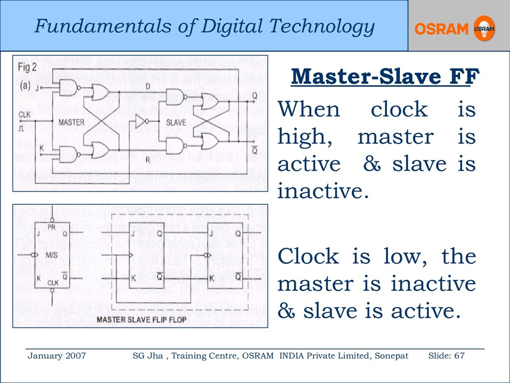
Centre, OSRAM INDIA Private Limited, Sonepat Slide: 67 Master-Slave FF When clock is high, master is active & slave is inactive. Clock is low, the master is inactive & slave is active.
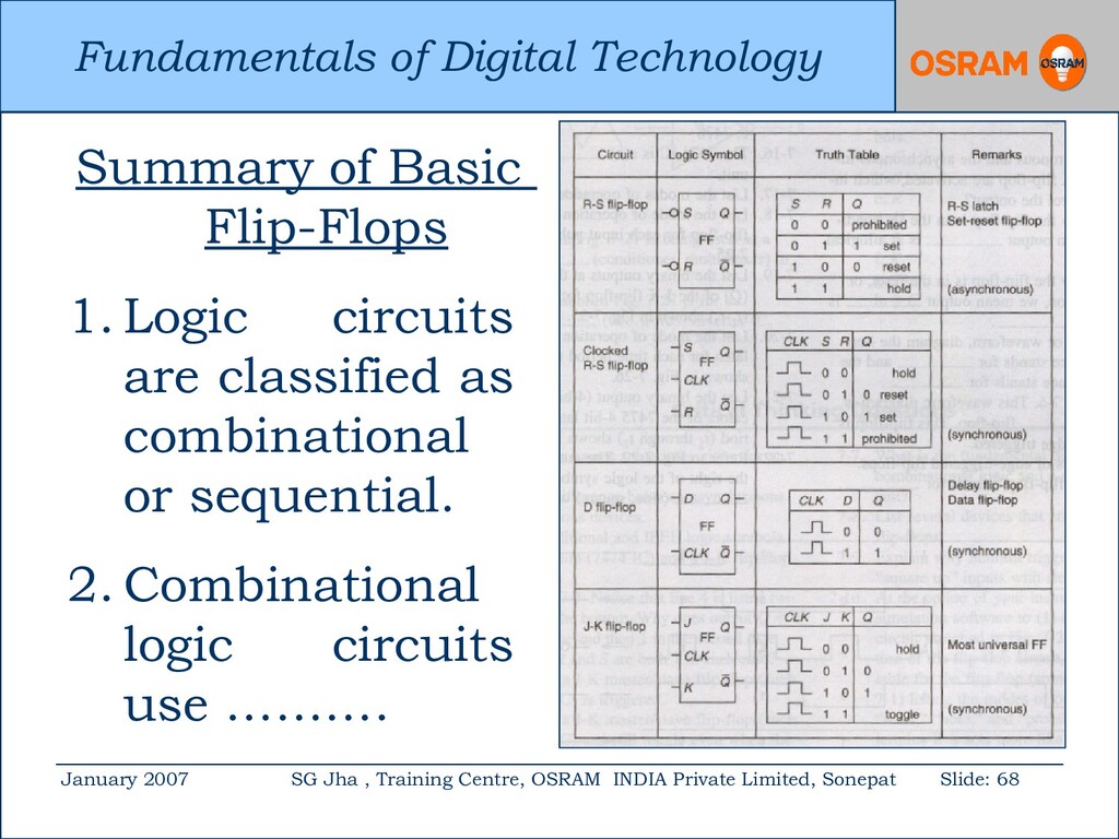
Centre, OSRAM INDIA Private Limited, Sonepat Slide: 68 Summary of Basic Flip-Flops 1. Logic circuits are classified as combinational or sequential. 2. Combinational logic circuits use ……….
Centre, OSRAM INDIA Private Limited, Sonepat Slide: 69 2. …… AND, OR & NOT gates which do not have memory. 3. Sequential logic circuits use flip-flop which has memory. 4. Flip-flops are wired together to form counters, registers etc. 5. Flip-flops are edge-triggered. 6. Schmitt triggers are special gates.
Centre, OSRAM INDIA Private Limited, Sonepat Slide: 71 Counters : 1. Counter is one of the most important subsystems in a digital system. 2. Counter circuit activated by a clock can count the number of clock cycles. 3. There are two types of counters; Ripple & Synchronous Counter.
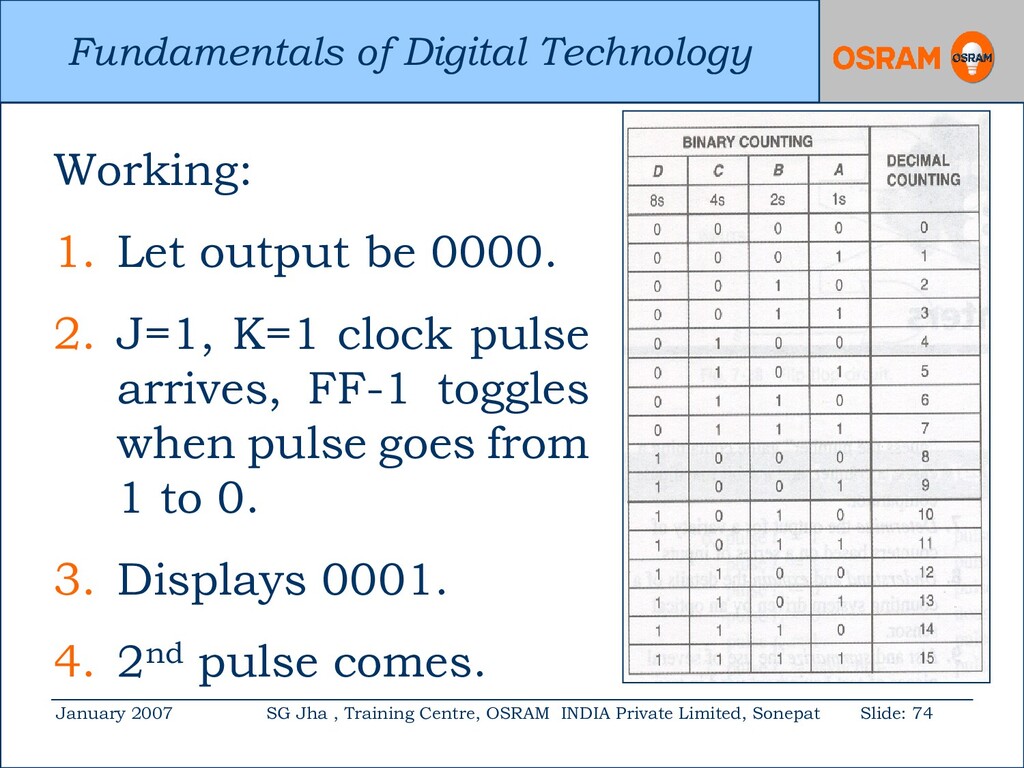
Centre, OSRAM INDIA Private Limited, Sonepat Slide: 72 Ripple counters: 1. The ripple counter is simple and requires less hardware. 2. However, it has speed limitation. 3. Each FF is triggered by the previous FF, and thus the counter has a cumulative settling time. 4. These counters are called Serial or Asynchronous.
Centre, OSRAM INDIA Private Limited, Sonepat Slide: 75 5. FF-1 toggles. Q becomes 0 which causes FF-2 to toggle. 6. Displays 0010. 7. 3rd clock pulse, FF-1 toggles, FF-2 does not because FF-1 has gone from 0 to 1 which is not negative. 8. Displays 0011. 9. This continues………………..
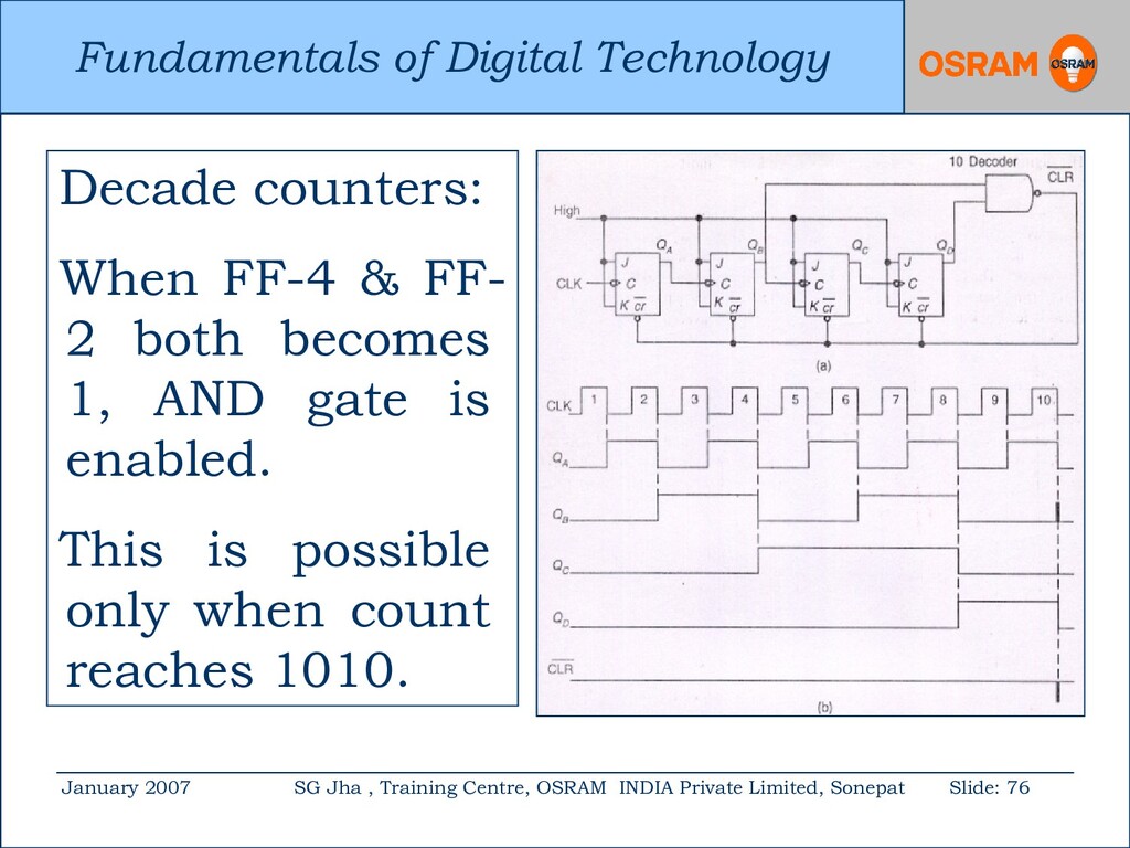
Centre, OSRAM INDIA Private Limited, Sonepat Slide: 76 Decade counters: When FF-4 & FF- 2 both becomes 1, AND gate is enabled. This is possible only when count reaches 1010.
Centre, OSRAM INDIA Private Limited, Sonepat Slide: 77 Synchronous counters: 1. Each flip-flop has a delay of μs. 2. A ripple counter has cascaded flip- flops in chain. 3. If there are ‘n’ flip-flops in the chain, there will be a total time delay of ‘n’ μs. 4. Thus, ripple counters are slow.
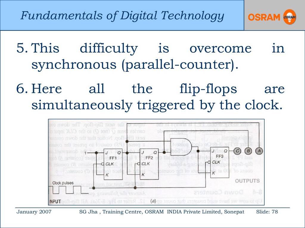
Centre, OSRAM INDIA Private Limited, Sonepat Slide: 78 5. This difficulty is overcome in synchronous (parallel-counter). 6. Here all the flip-flops are simultaneously triggered by the clock.
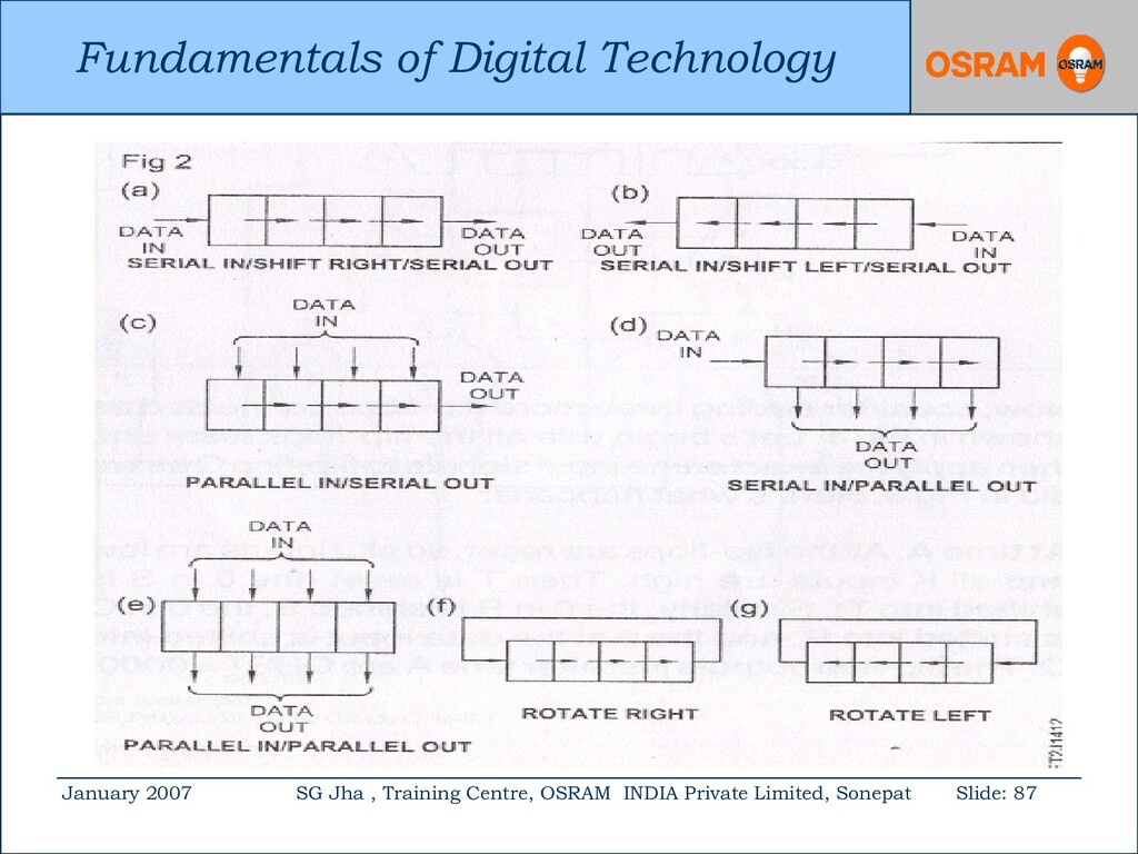
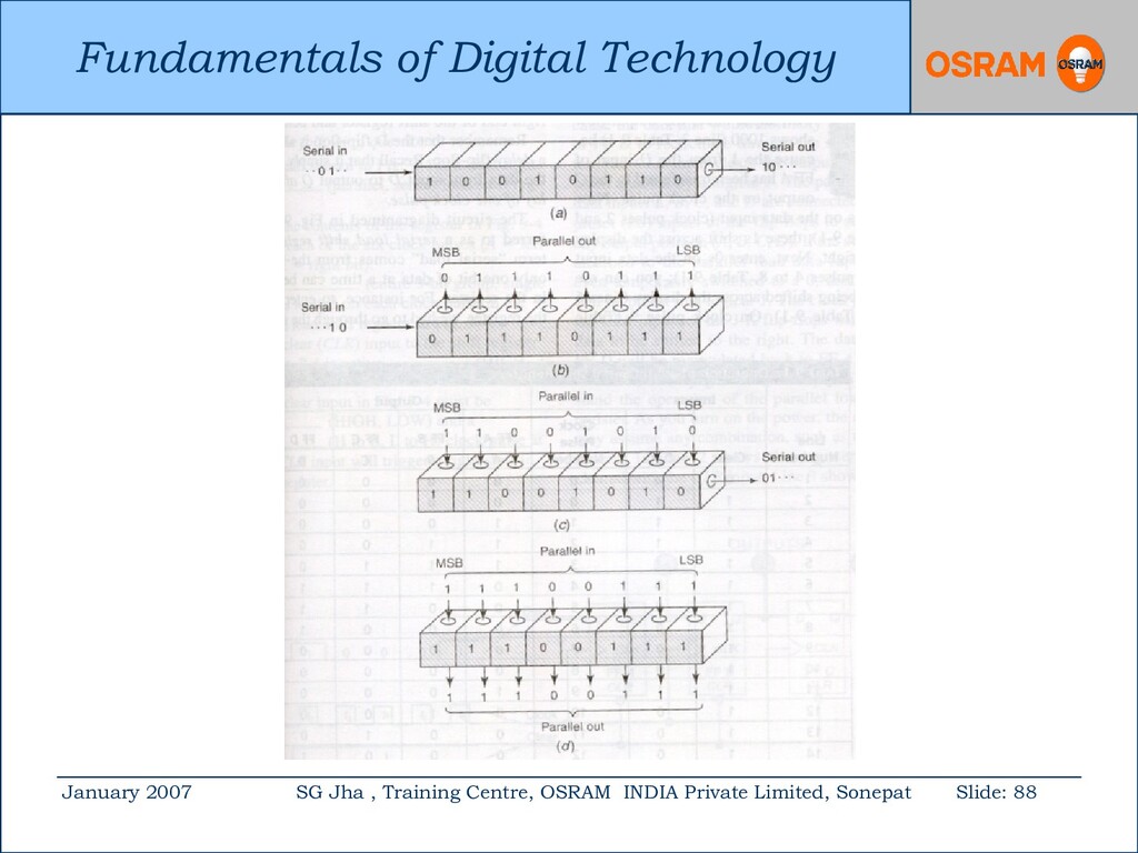
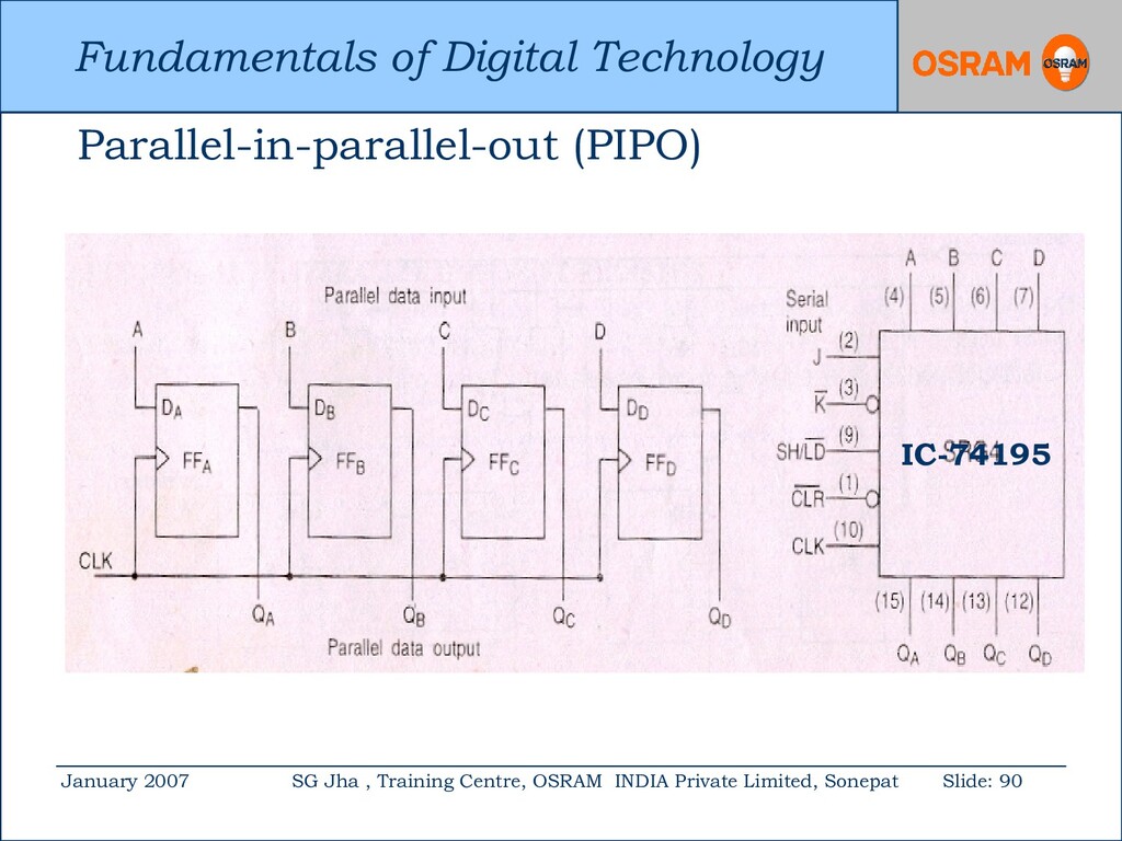
Centre, OSRAM INDIA Private Limited, Sonepat Slide: 83 Registers is a group of flip-flops that can be used to store a binary number. It find a variety of applications in digital system. If the output of each flip-flop is connected to the input of the adjacent flip-flop, then the circuit is called a shift register.
Centre, OSRAM INDIA Private Limited, Sonepat Slide: 84 Shift-Registers: • A typical example of a shift register is found within a calculator. • It is a temporary memory and thus holds the numbers on the display. • It also shifts the number to the left on the display each time a new key is pressed.
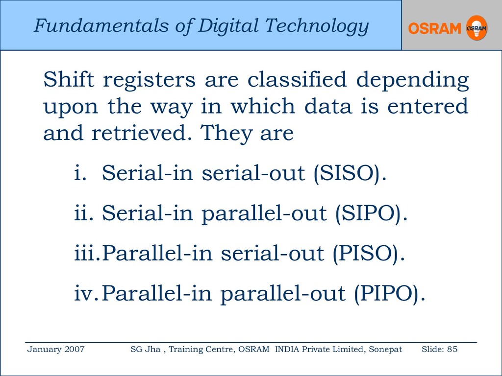
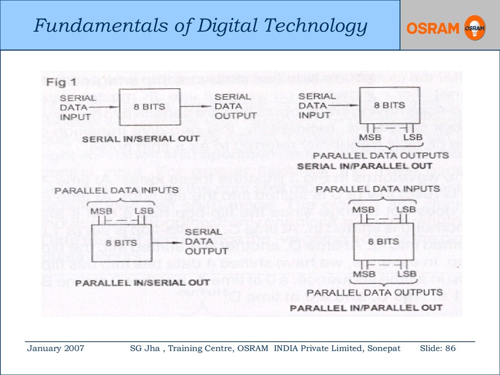
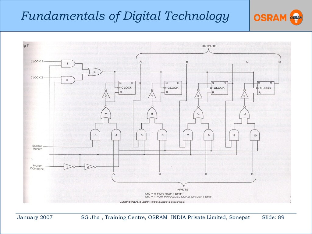
Centre, OSRAM INDIA Private Limited, Sonepat Slide: 85 Shift registers are classified depending upon the way in which data is entered and retrieved. They are i. Serial-in serial-out (SISO). ii. Serial-in parallel-out (SIPO). iii.Parallel-in serial-out (PISO). iv.Parallel-in parallel-out (PIPO).
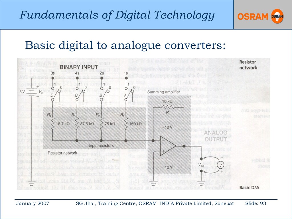
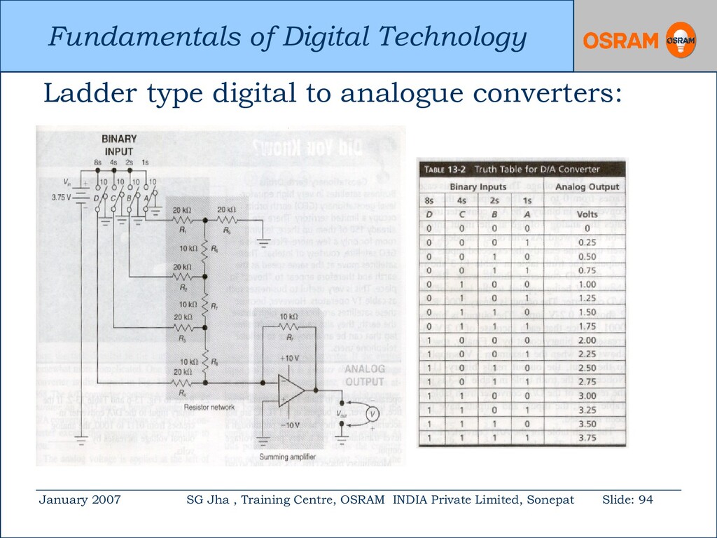
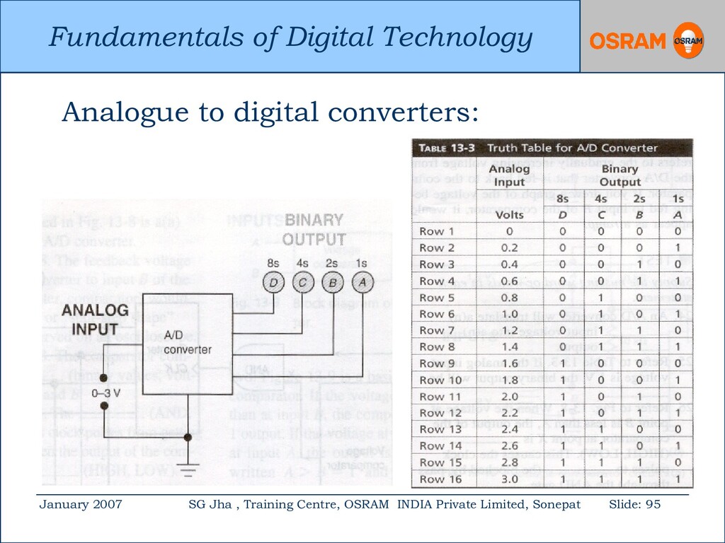
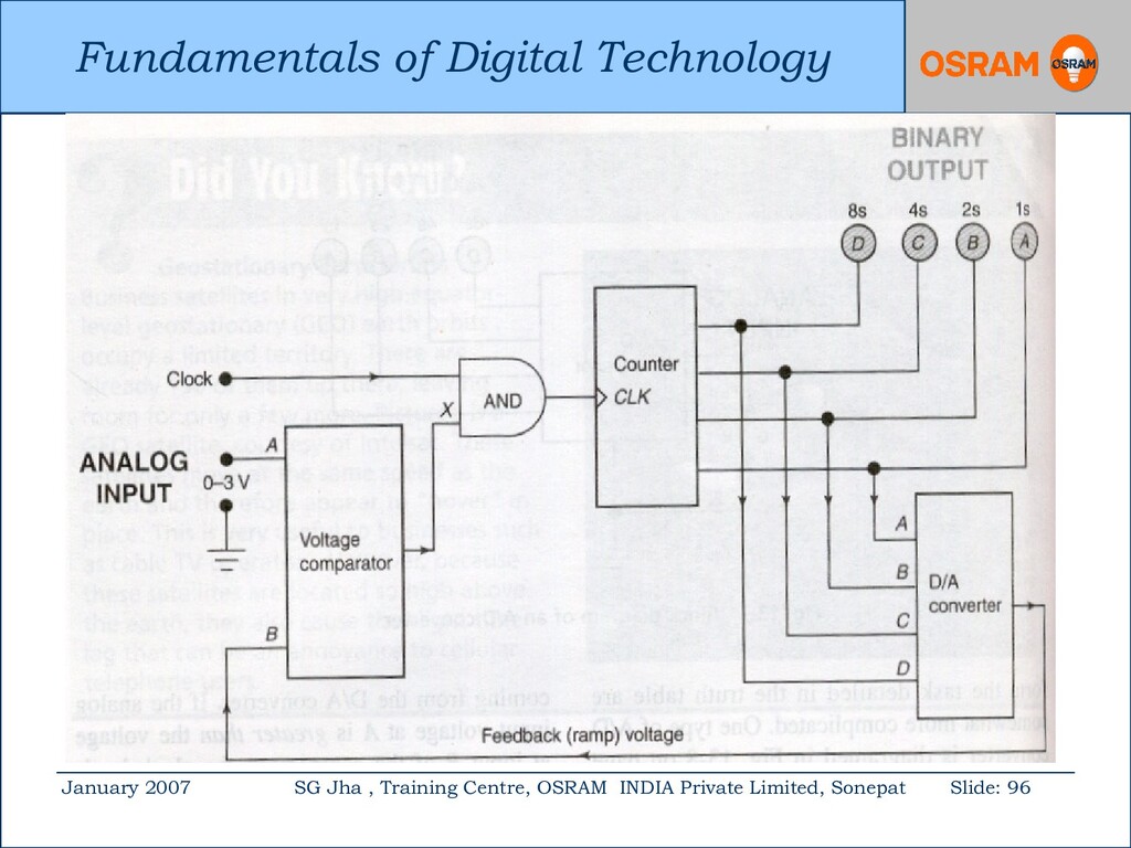
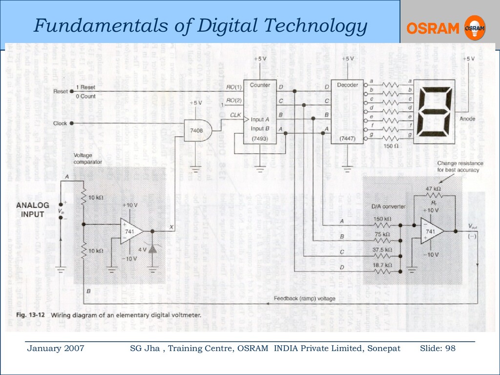
Centre, OSRAM INDIA Private Limited, Sonepat Slide: 92 Converters: 1. Physical quantities such as pressure, temperature and flow are analogue in nature. 2. Converters are those circuits which converts analogue values into digital and vice-versa.
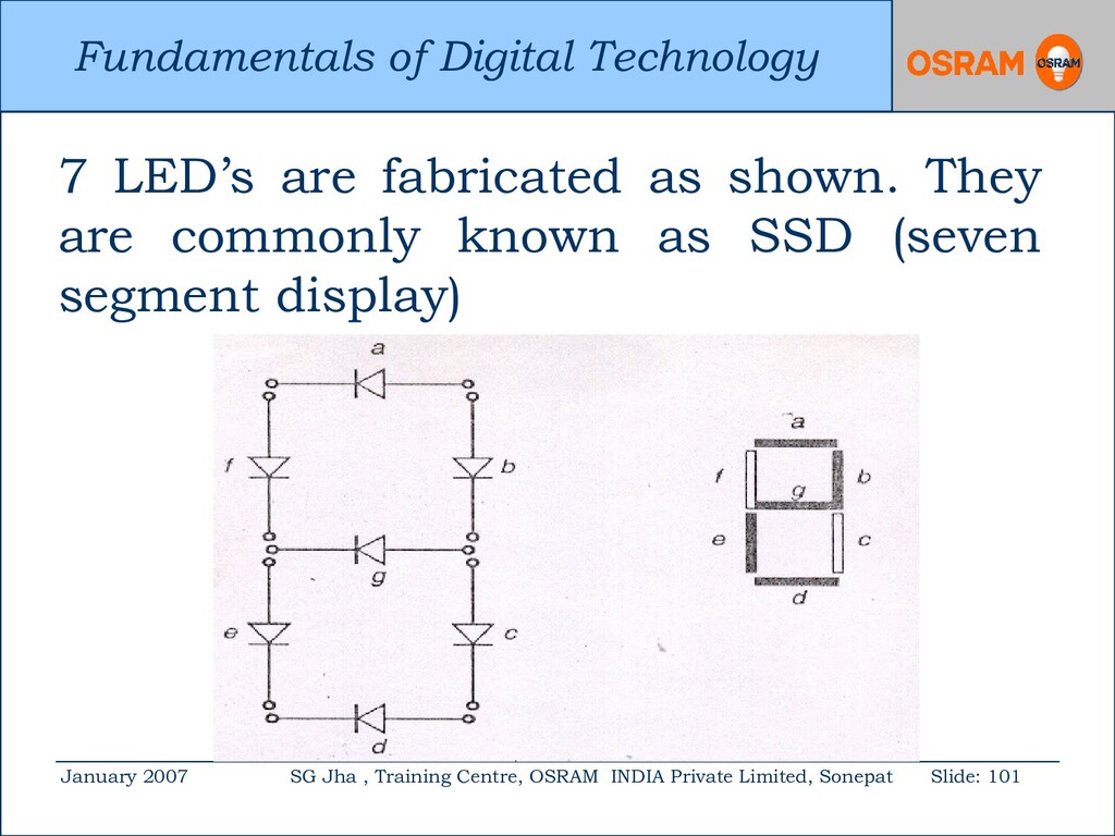
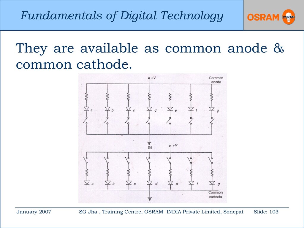
Centre, OSRAM INDIA Private Limited, Sonepat Slide: 102 They are used for displaying decimal numbers because; 1. Power 1.5-5V, 10-150 mW per digit. 2. Good brightness level. 3. Temperature range –40 to + 85 C. 4. Life time is around 100,000 hours. 5. Emits light in ROY & W.
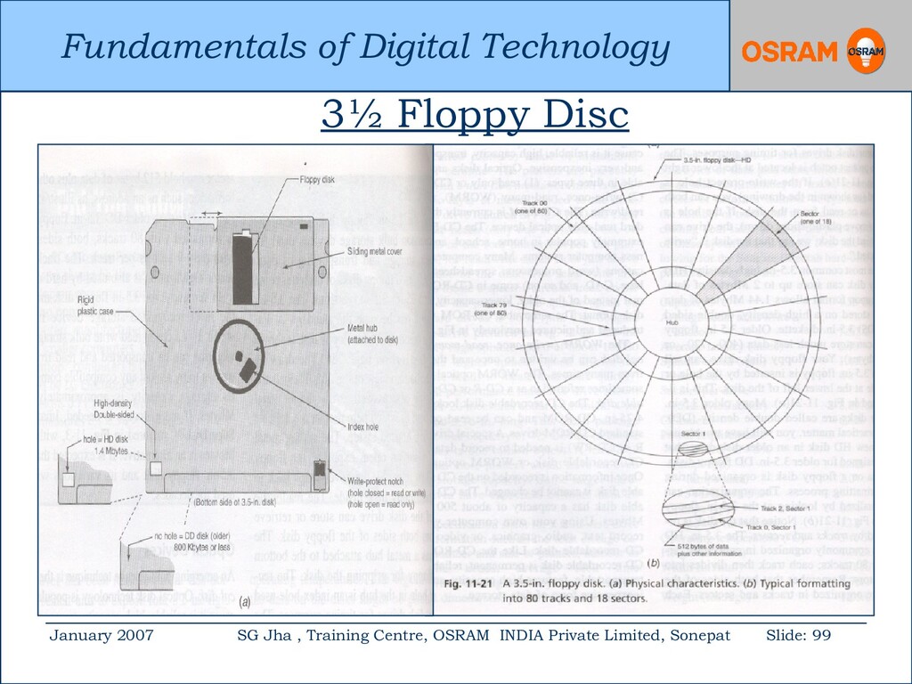
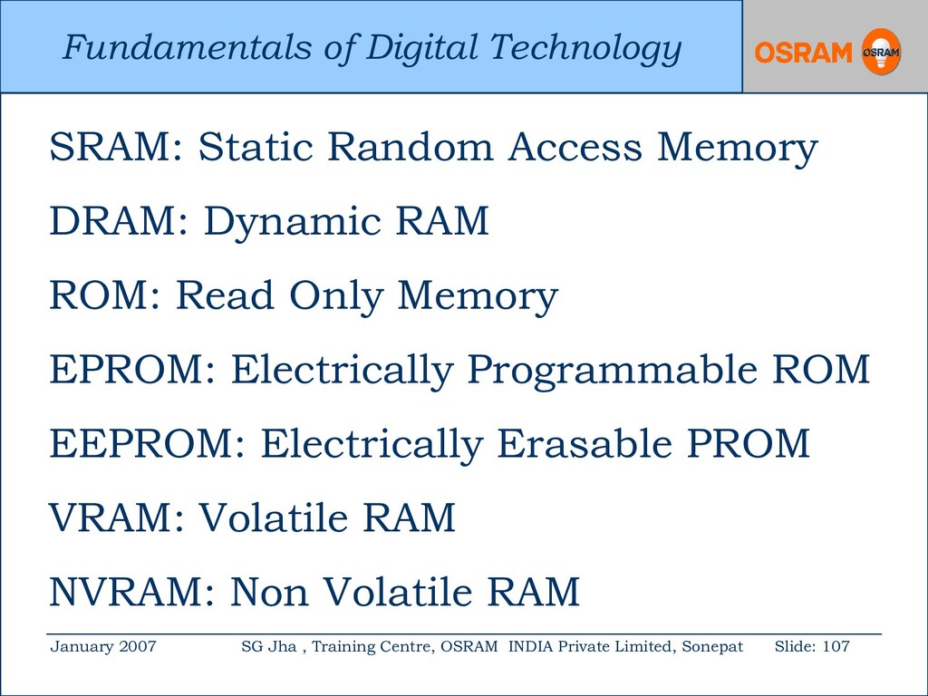
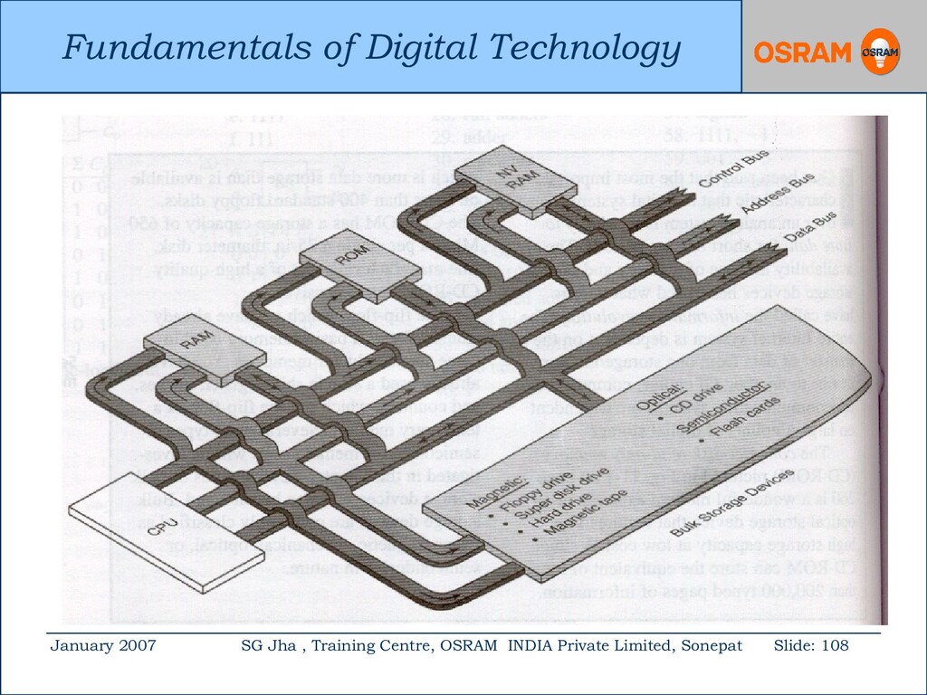
Centre, OSRAM INDIA Private Limited, Sonepat Slide: 105 ROM: Read Only Memory Compact disc read only memory CD- ROM is the most wonderful example. It is an optical storage device. It can store information equivalent of more than 200,000 typed pages. The cost of CDROM is around Rs.5/-.
Centre, OSRAM INDIA Private Limited, Sonepat Slide: 106 RAM: Random Access Memory RAM is a read/write or scratchpad memory. The RAM can not be used for permanent memory because it loses its data when the power is switched off. RAM is used where only a temporary memory is needed.
Centre, OSRAM INDIA Private Limited, Sonepat Slide: 110 Basic constituents of a computer: 1. Input 2. Memory 3. Instruction 4. Arithmetic logic unit and 5. Output
Centre, OSRAM INDIA Private Limited, Sonepat Slide: 112 Input: This transfers a set of instructions called a program and a set of numbers or other information known as data to the computer. Memory : Here the program and data are stored.
Centre, OSRAM INDIA Private Limited, Sonepat Slide: 113 Instructions : This parts of a computer does the job of a human. Arithmetic Logic Units: This section adds, subtracts, multiplies and divides. Output: This transfers the final answer from the computer to the outside world.
Centre, OSRAM INDIA Private Limited, Sonepat Slide: 115 The mechanical power may be transmitted at the desired speed & torque by any one of the following methods. 1. Direct drive. 2. Belt drive 3. Rope drive 4. Chain drive and 5. Gear drive.
Centre, OSRAM INDIA Private Limited, Sonepat Slide: 116 Advantages of Electric Drives : 1. It is simple in construction and has less maintenance cost. 2. Its speed control is easy and smooth. 3. It is neat, clean and free from any smoke or flue gases. 4. It has comparatively longer life.
Centre, OSRAM INDIA Private Limited, Sonepat Slide: 117 5. It can be installed at any desired convenient place thus affording more flexibility in the lay out. 6. It can be remotely controlled. 7. Being compact, it requires less space. 8. It can be started immediately without any loss of time.
Centre, OSRAM INDIA Private Limited, Sonepat Slide: 118 Disadvantages: 1. It comes to stop as soon as there is failure of electric supply. 2. It can not be used at far off places which are not served by electric supply.
Centre, OSRAM INDIA Private Limited, Sonepat Slide: 119 Electric drives may be grouped into: 1. Group drive 2. Individual drive 3. Multi-motor drive. Each has its own merits & de-merits.
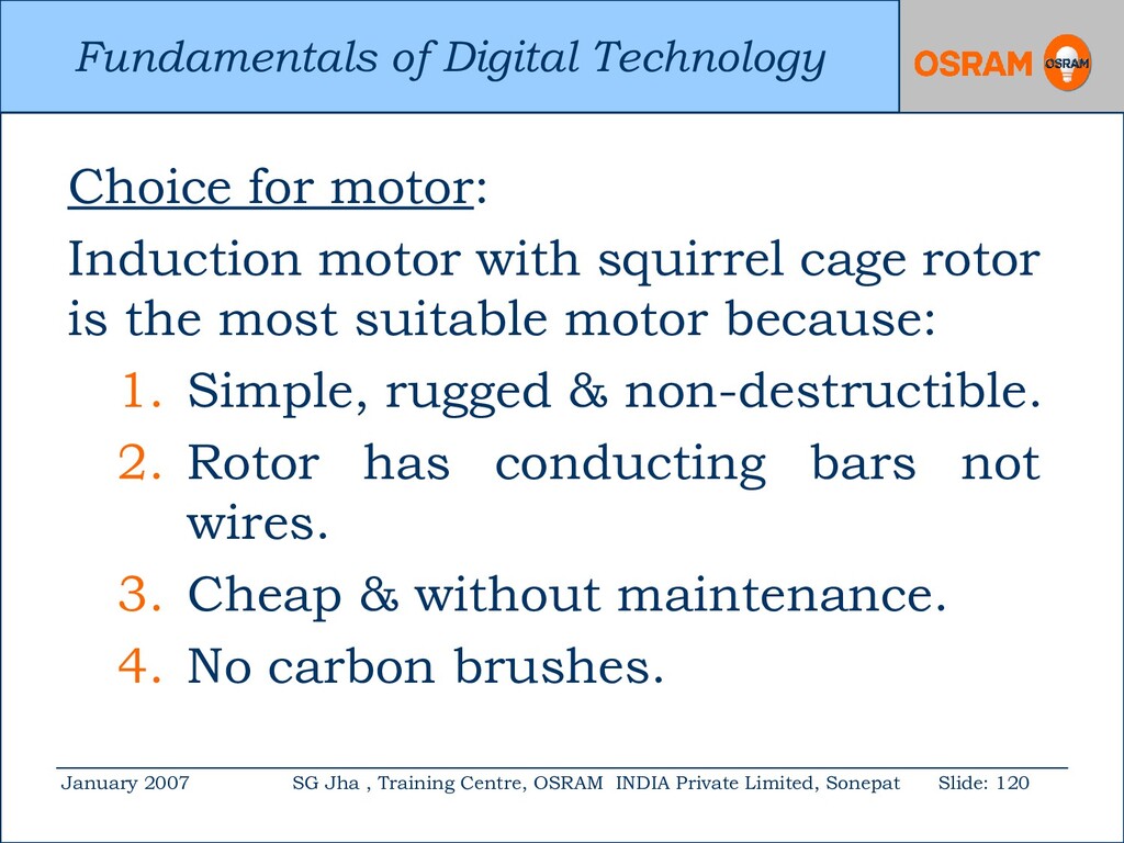
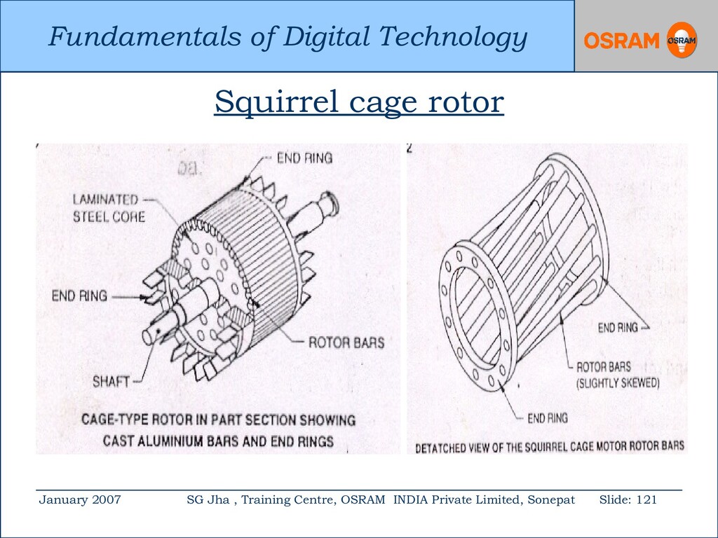
Centre, OSRAM INDIA Private Limited, Sonepat Slide: 120 Choice for motor: Induction motor with squirrel cage rotor is the most suitable motor because: 1. Simple, rugged & non-destructible. 2. Rotor has conducting bars not wires. 3. Cheap & without maintenance. 4. No carbon brushes.
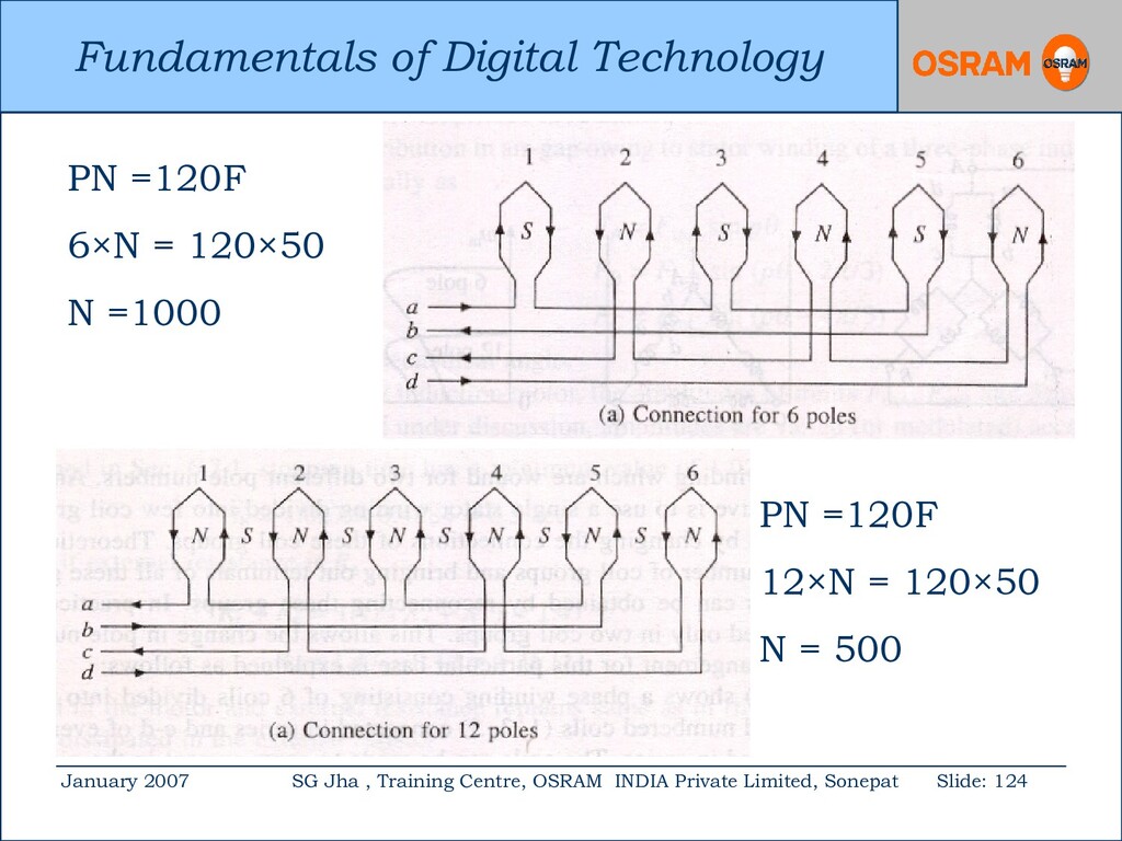
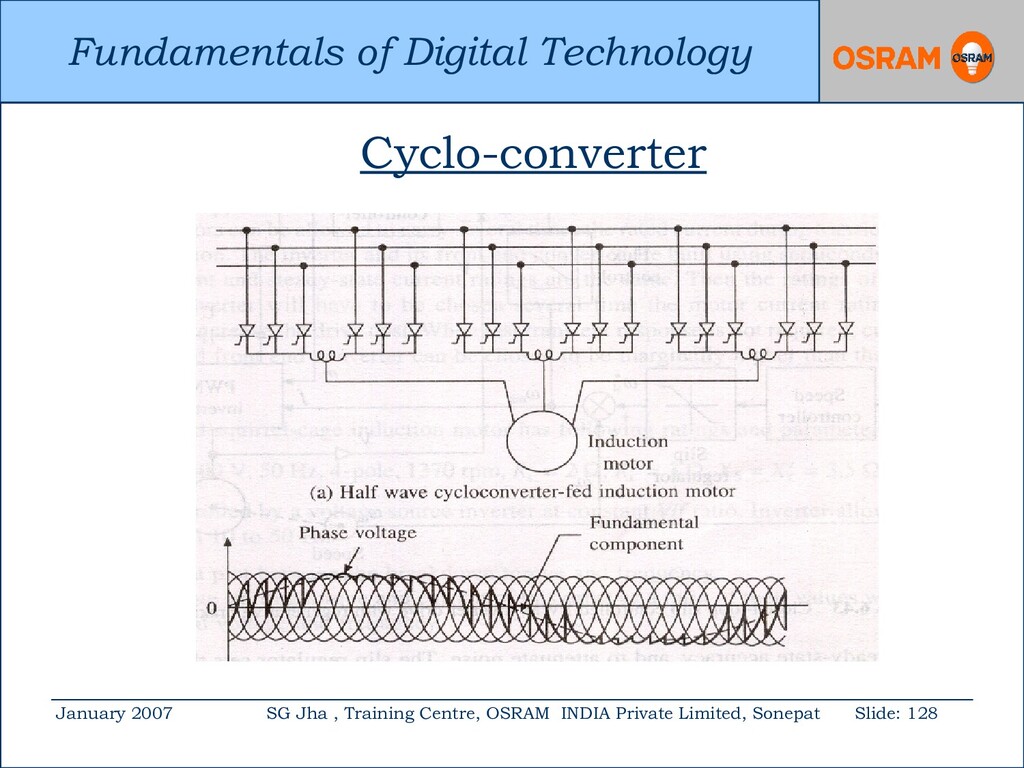
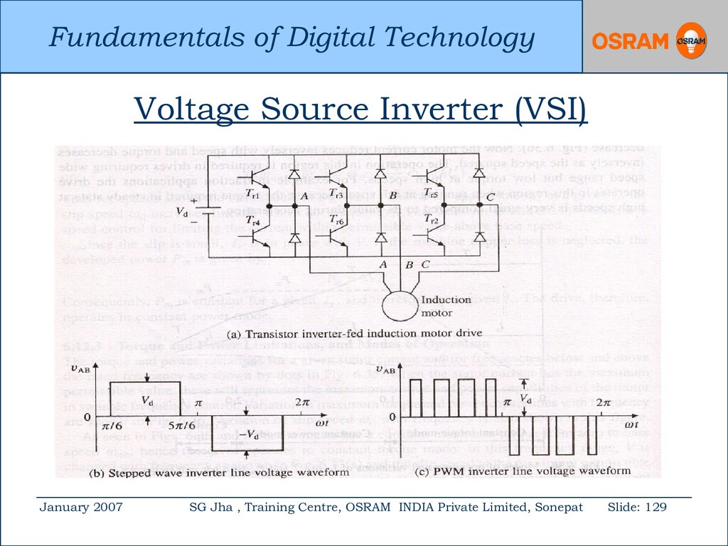
Centre, OSRAM INDIA Private Limited, Sonepat Slide: 122 Speed: When a three phase winding is energised by a three phase supply, it rotates around the stator synchronously. Synchronous speed Ns = 120 f / P where P is the number of motor poles and f is the frequency of the stator a.c. supply.
Centre, OSRAM INDIA Private Limited, Sonepat Slide: 123 Therefore to change the rpm of the motor, either the number of poles or supply frequency needs to be changed. Changing either of them is not a easy task. In the AC drives, the supply frequency is varied depending upon the required rpm.
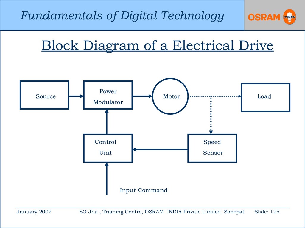
Centre, OSRAM INDIA Private Limited, Sonepat Slide: 125 Block Diagram of a Electrical Drive Source Motor Load Power Modulator Control Unit Speed Sensor Input Command
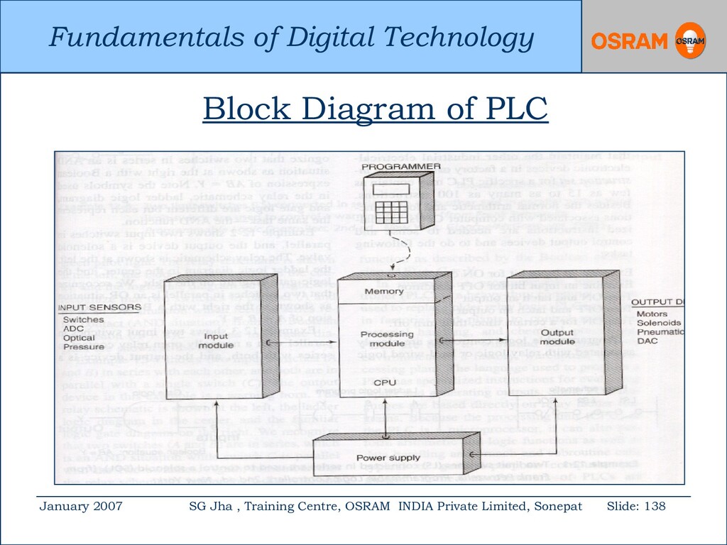
Centre, OSRAM INDIA Private Limited, Sonepat Slide: 132 Programmable logic controller (PLC) is a special computer like device. It is called work horse of an industrial automation. It is used to replace banks of elctro- magnetic relays in industrial process control.
Centre, OSRAM INDIA Private Limited, Sonepat Slide: 133 It is based on digital logic and can be programmed as and when required. All production processes go through a fixed repetitive sequence of operations. This involves logical steps and decision. It controls time and regulate sequence.
Centre, OSRAM INDIA Private Limited, Sonepat Slide: 134 It has special programming because it has to control the machines. A normal computer has a key board or mouse for primary input but PLC’s have sensors. PLC’s can be re-programmed to meet the works requirement. It uses ladder logic programme.
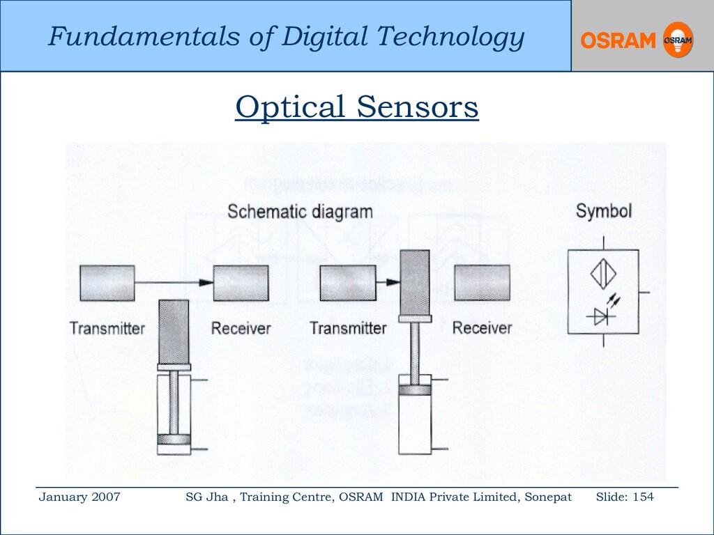
Centre, OSRAM INDIA Private Limited, Sonepat Slide: 135 It interfaces with input and output devices. The common input devices are 1. limit switches 2. pressure switches 3. temperature & optical sensors 4. analogue to digital converters etc.
Centre, OSRAM INDIA Private Limited, Sonepat Slide: 136 The common output devices are 1. motors 2. solenoids 3. pneumatic valves 4. digital to analogue converters etc.
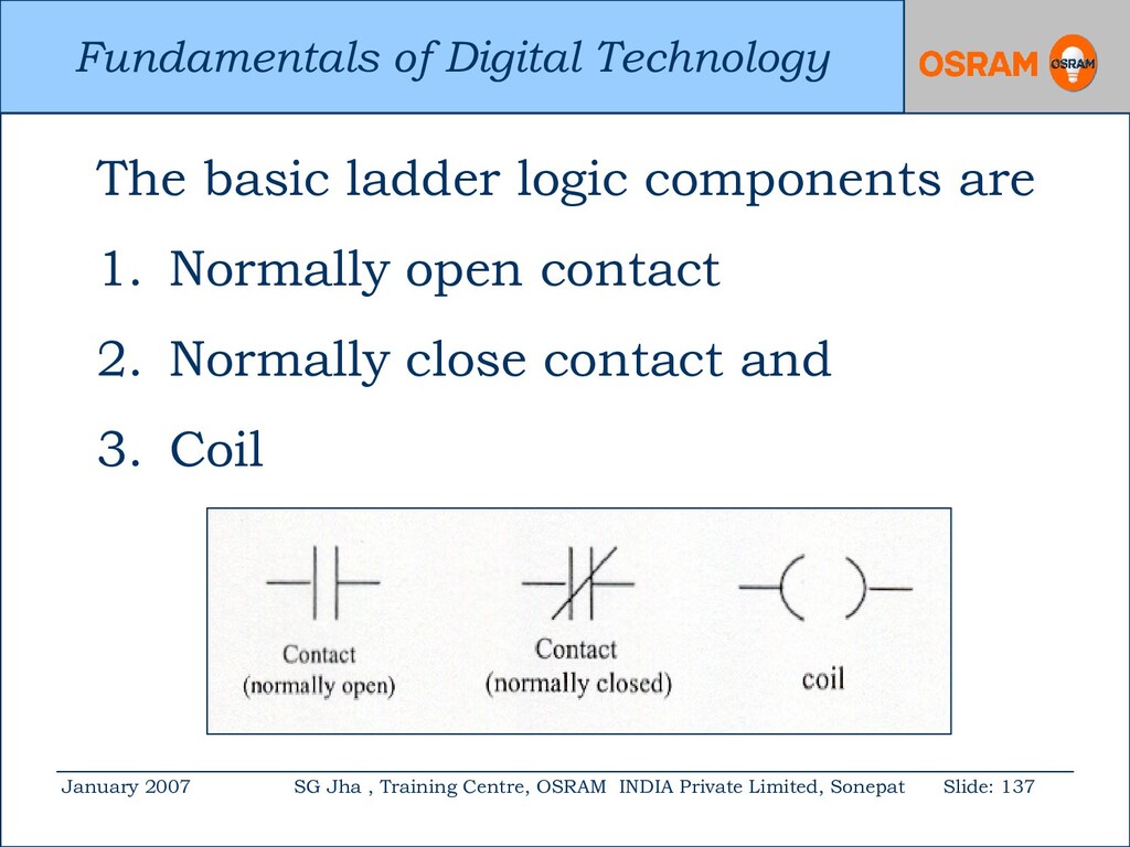
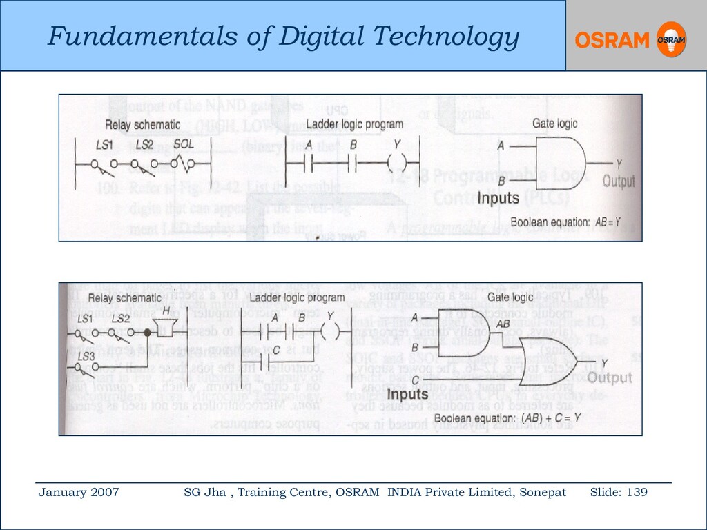
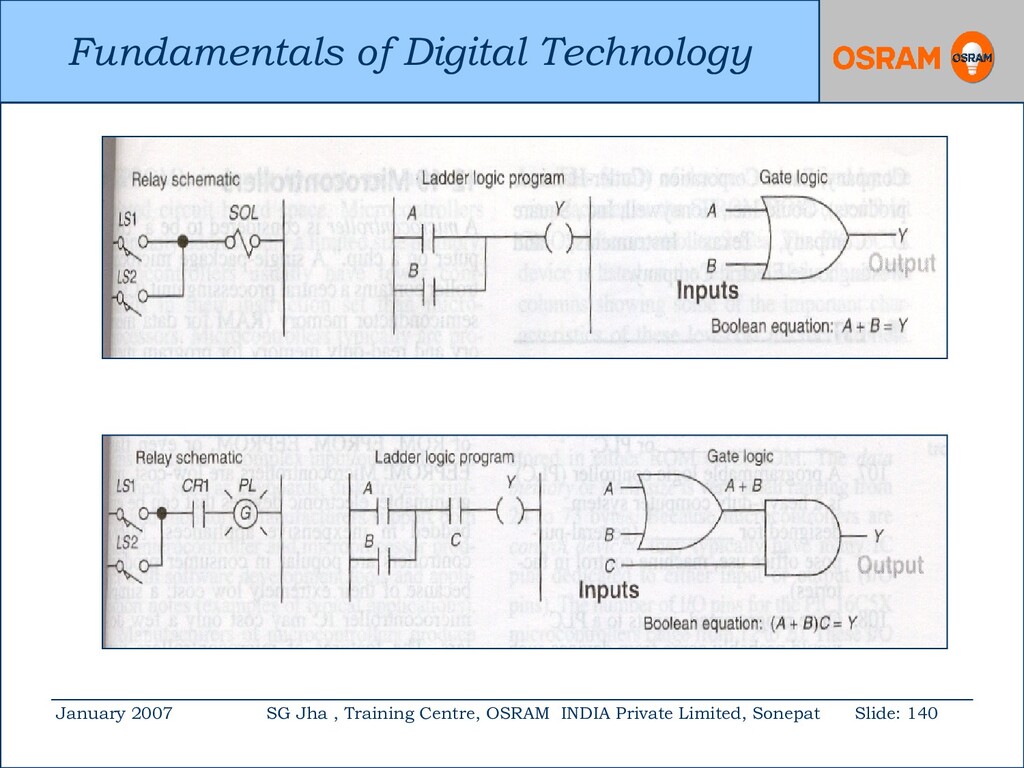
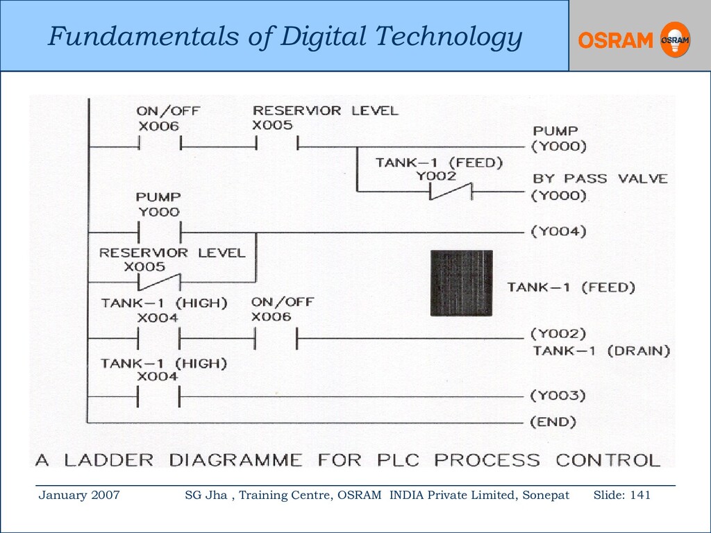
Centre, OSRAM INDIA Private Limited, Sonepat Slide: 137 The basic ladder logic components are 1. Normally open contact 2. Normally close contact and 3. Coil
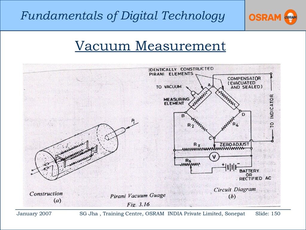
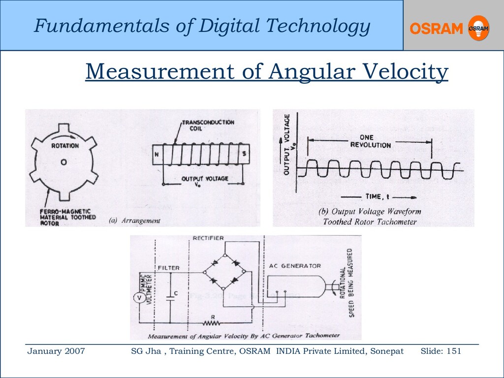
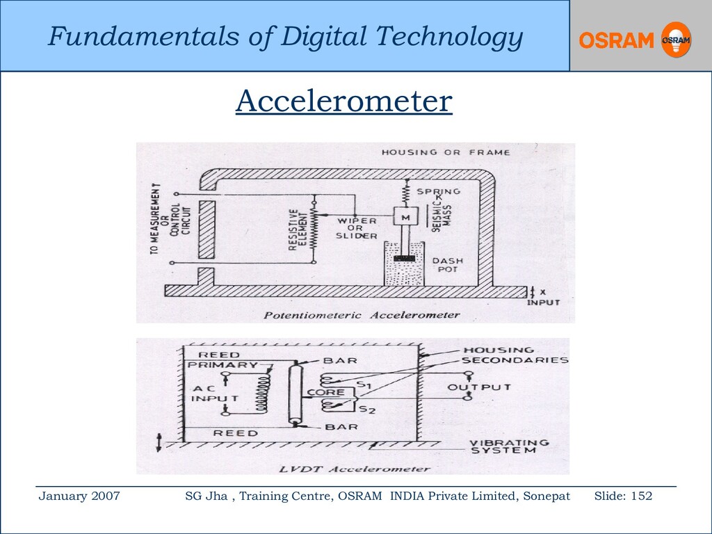
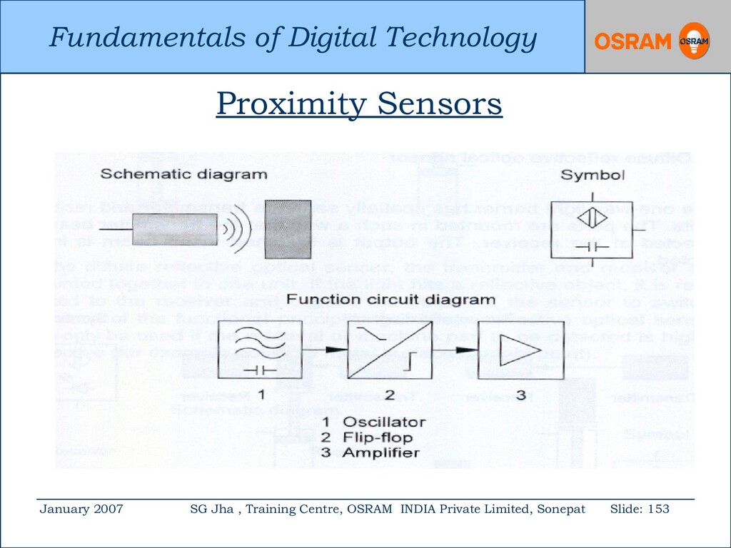
Centre, OSRAM INDIA Private Limited, Sonepat Slide: 143 Transducers: 1. Transducer is a device, which converts energy or information from one form to another. 2. These are widely used in measurement work. 3. It provides a usable output in response to specific input.
Centre, OSRAM INDIA Private Limited, Sonepat Slide: 144 The transducer may be; 1. Mechanical 2. Electrical 3. Magnetic 4. Optical 5. Chemical 6. Acoustic 7. Thermal 8. Nuclear Also it may be the combination of any two or more of these.
Centre, OSRAM INDIA Private Limited, Sonepat Slide: 145 Advantages: Electrical Transducers 1. Minimum friction. 2. Very small power is required. 3. The electrical output can be amplified to any desired level. 4. The output can be indicated and recorded remotely. 5. The signal may be in the form of voltage, current, frequency, pulses
Centre, OSRAM INDIA Private Limited, Sonepat Slide: 146 Dis-advantages: 1. Low reliability in comparison to that of mechanical transducers. 2. Comparative high cost. 3. In some cases accuracy and resolution attainable are not as high as in mechanical transducers 4. Dependency on power.