6/16
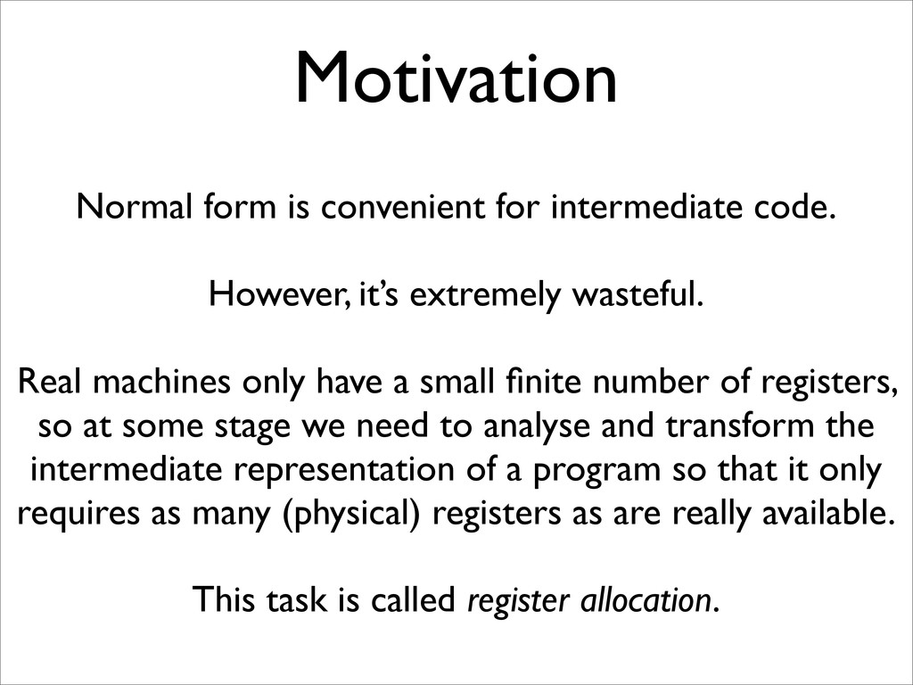
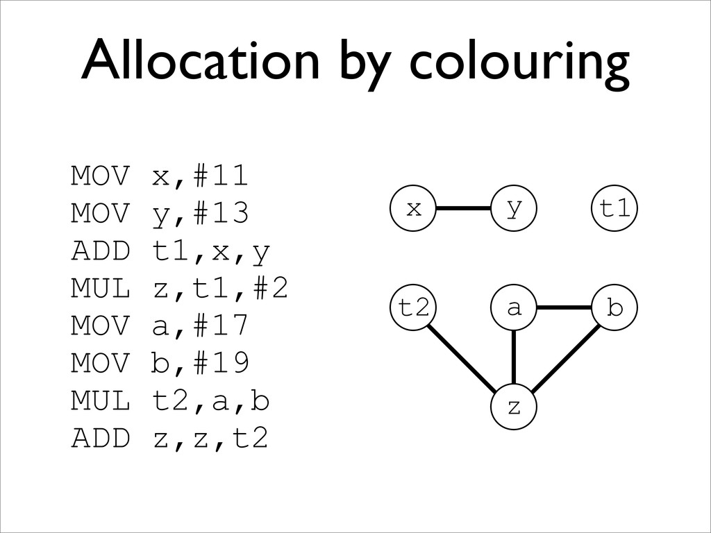
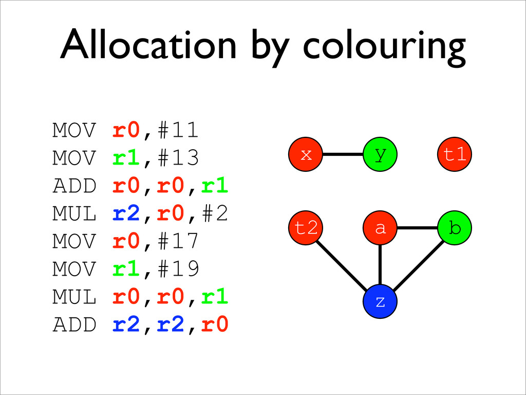
* A register allocation phase is required to assign each virtual register to a physical one during compilation
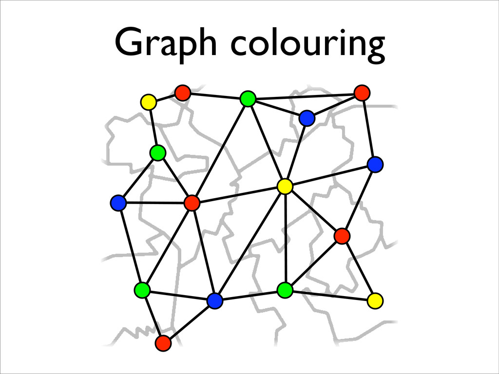
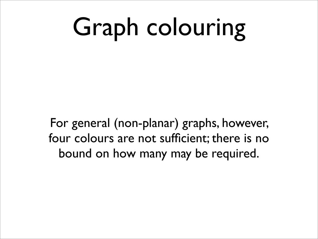
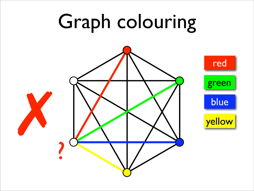
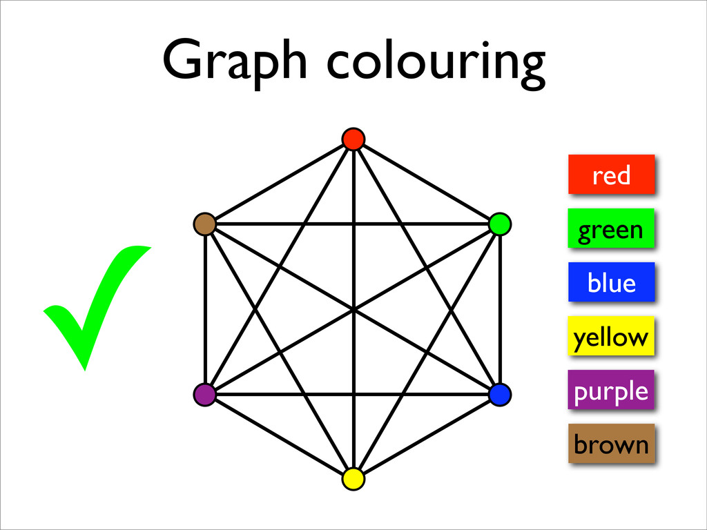
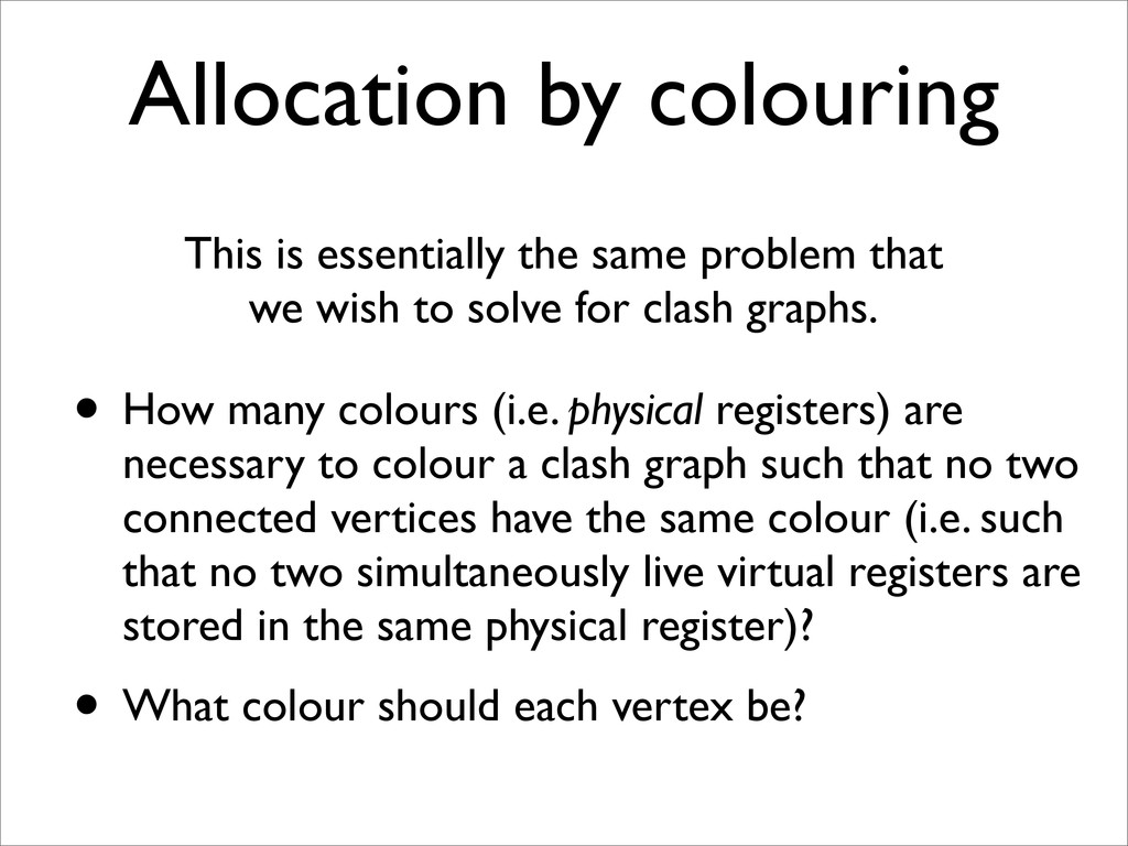
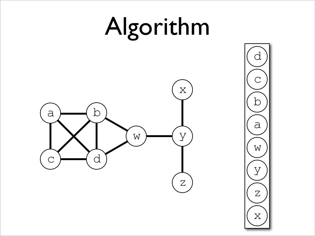
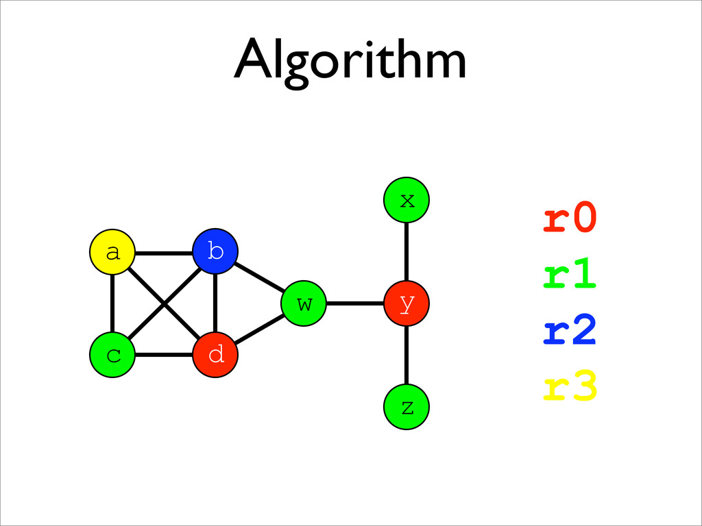
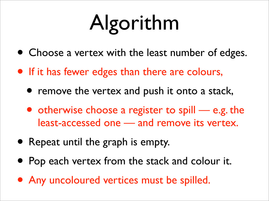
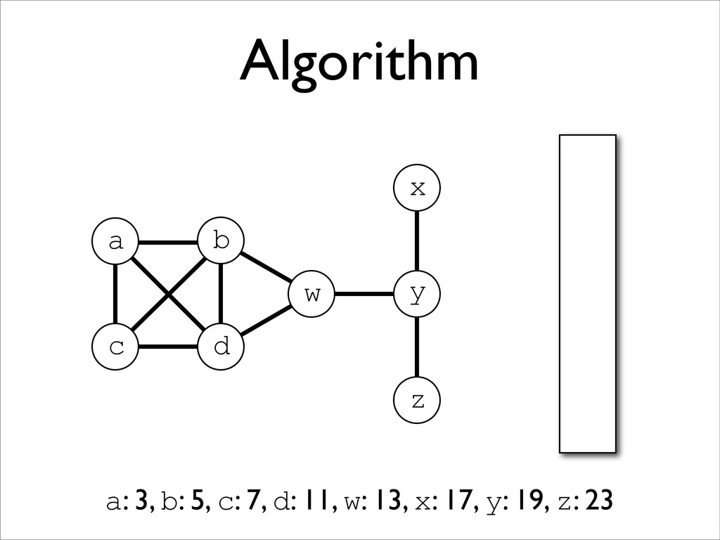
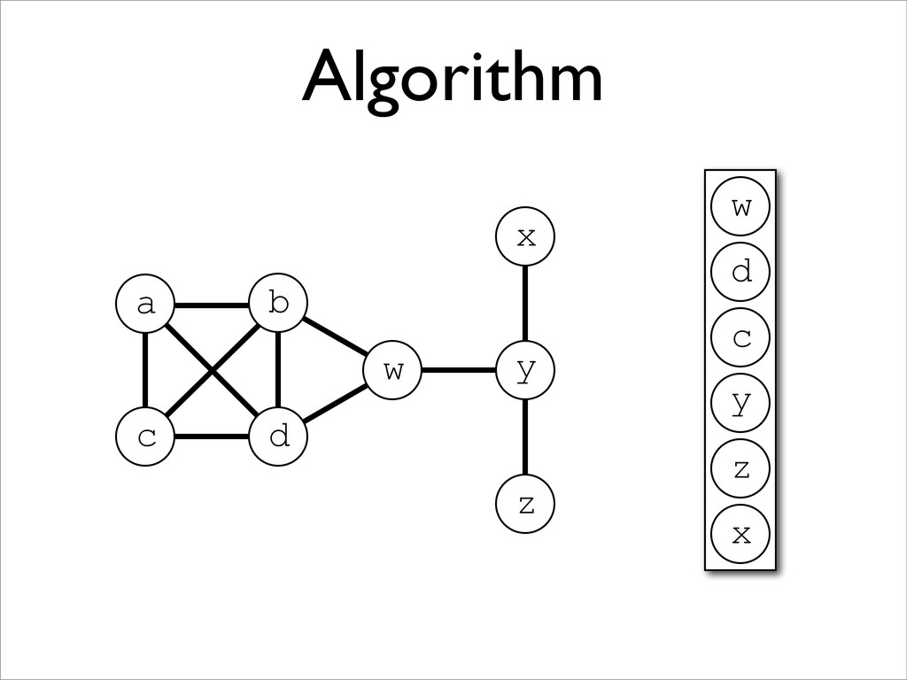
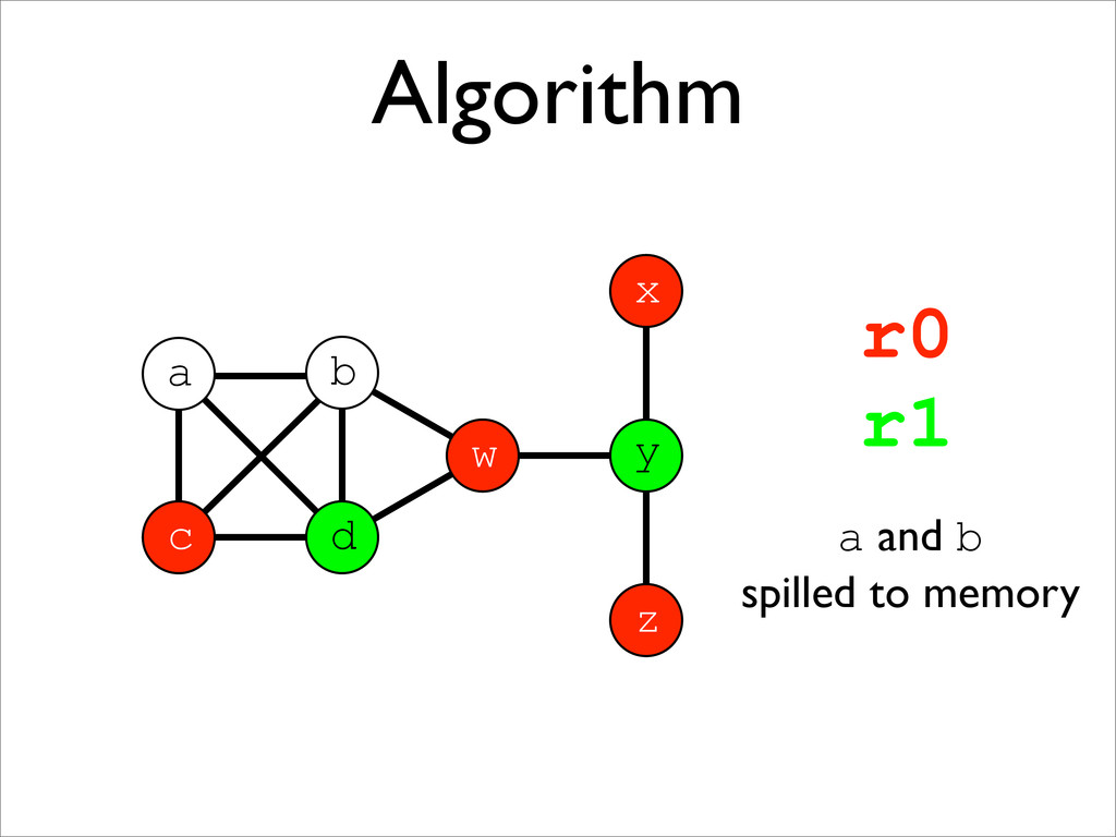
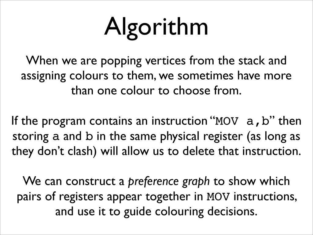
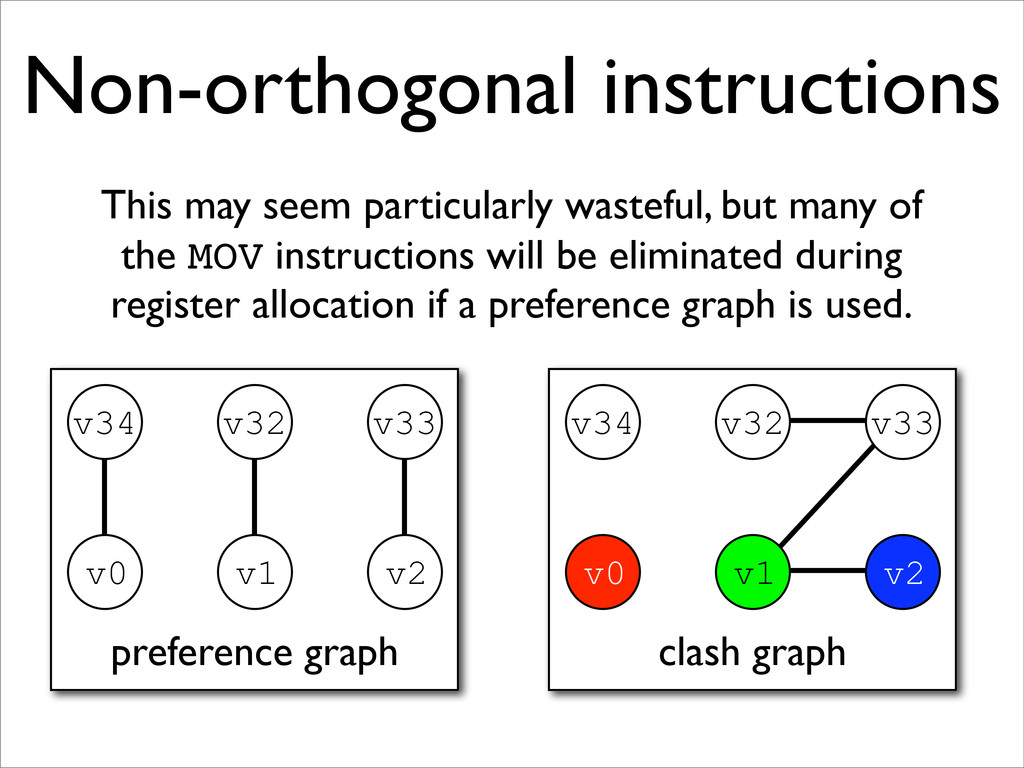
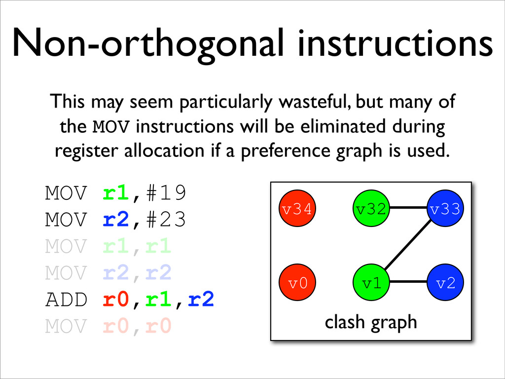
* Registers may be allocated by colouring the vertices of a clash graph
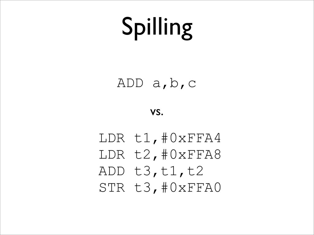
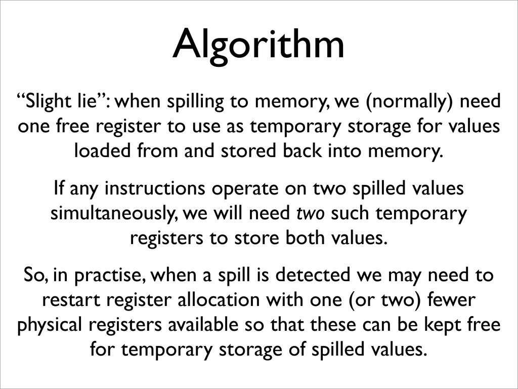
* When the number of physical registers is limited, some virtual registers may be spilled to memory
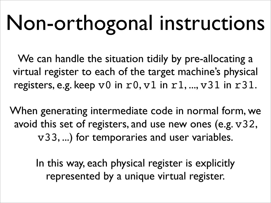
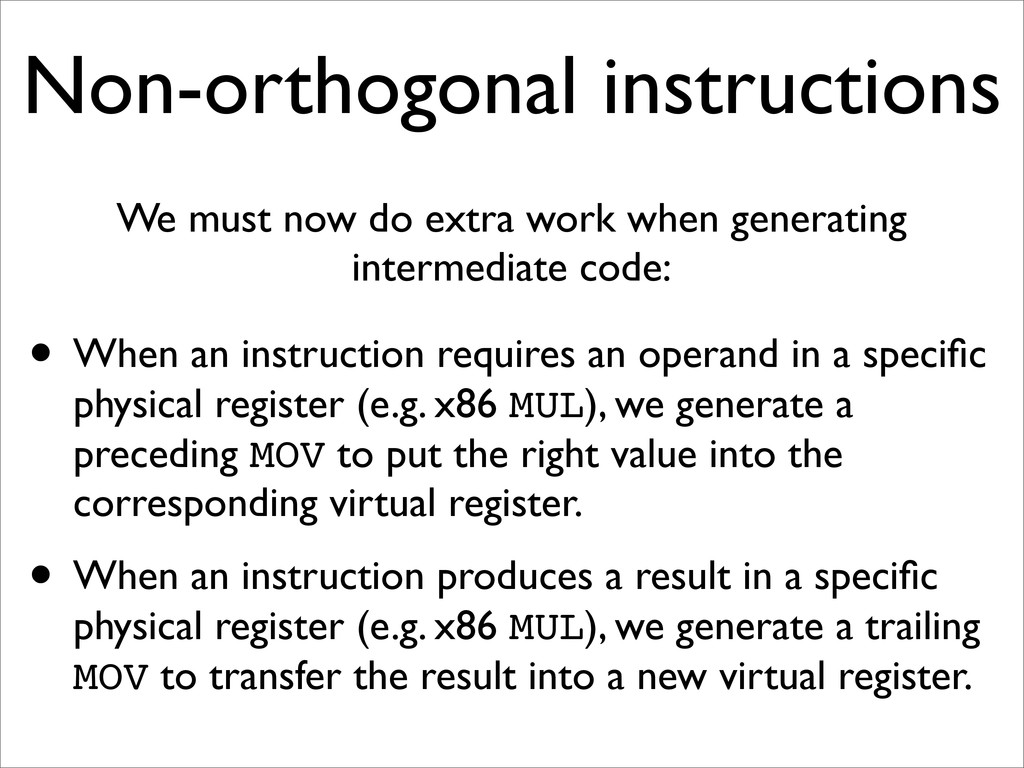
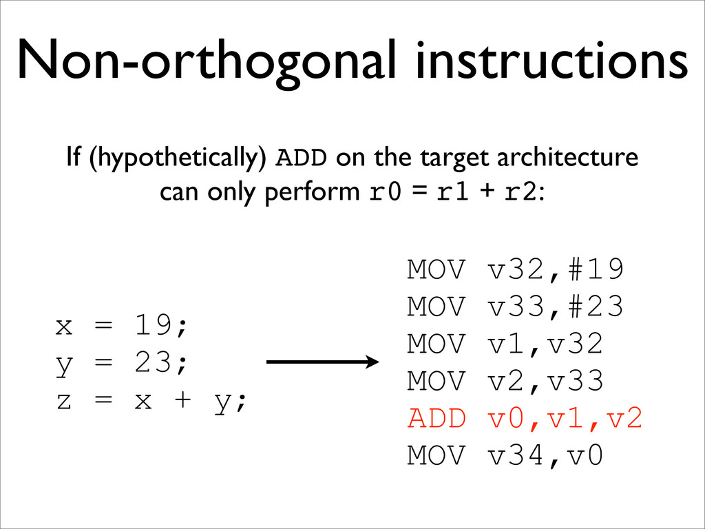
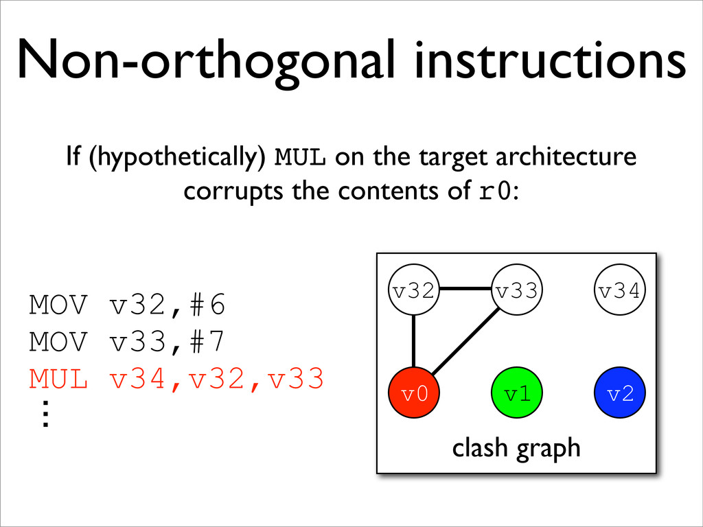
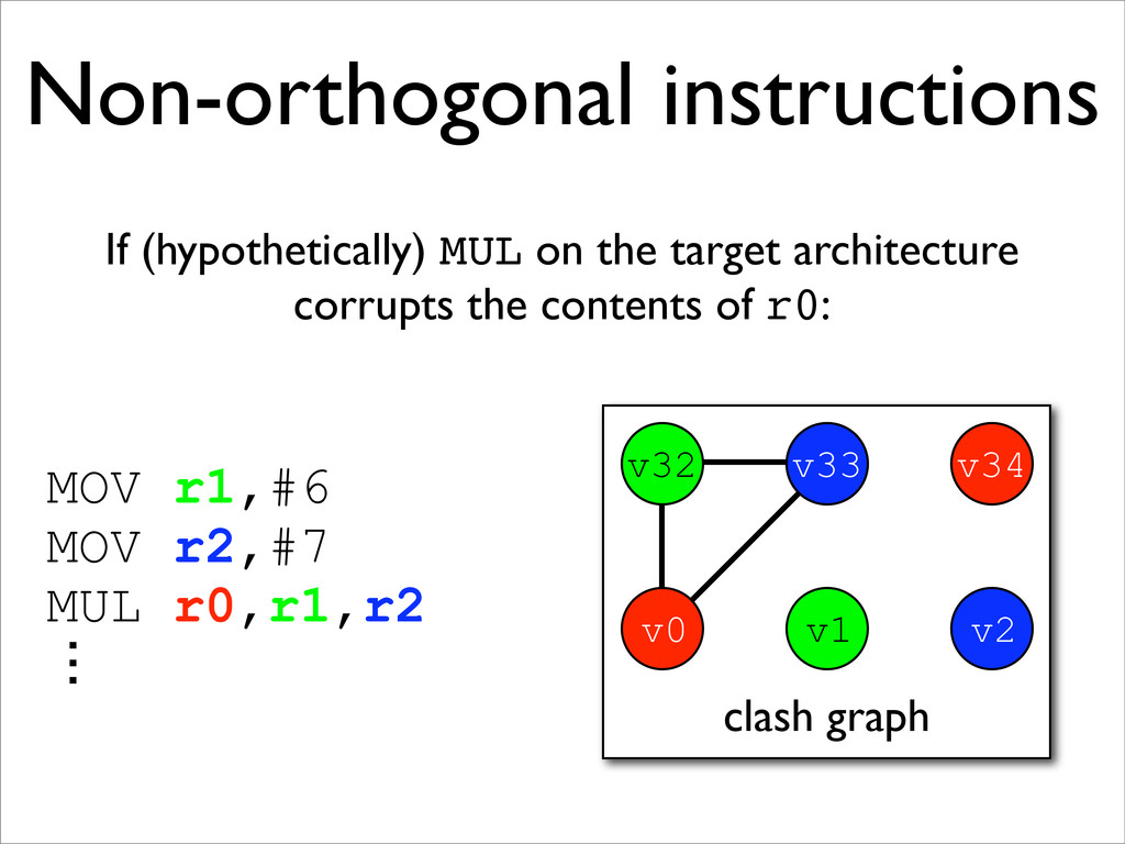
* Non-orthogonal instructions may be handled with additional MOVs and new edges on the clash graph
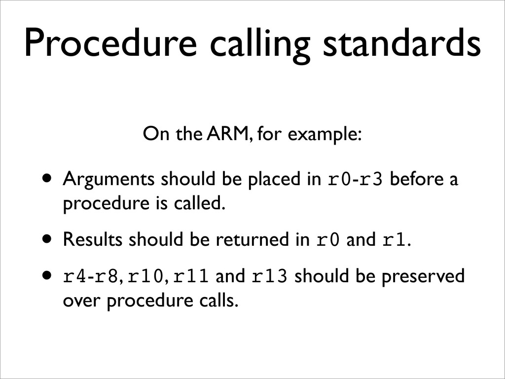
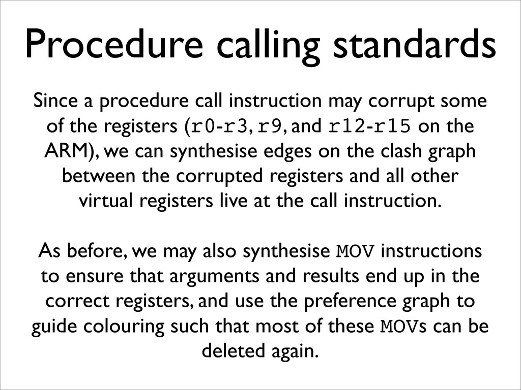
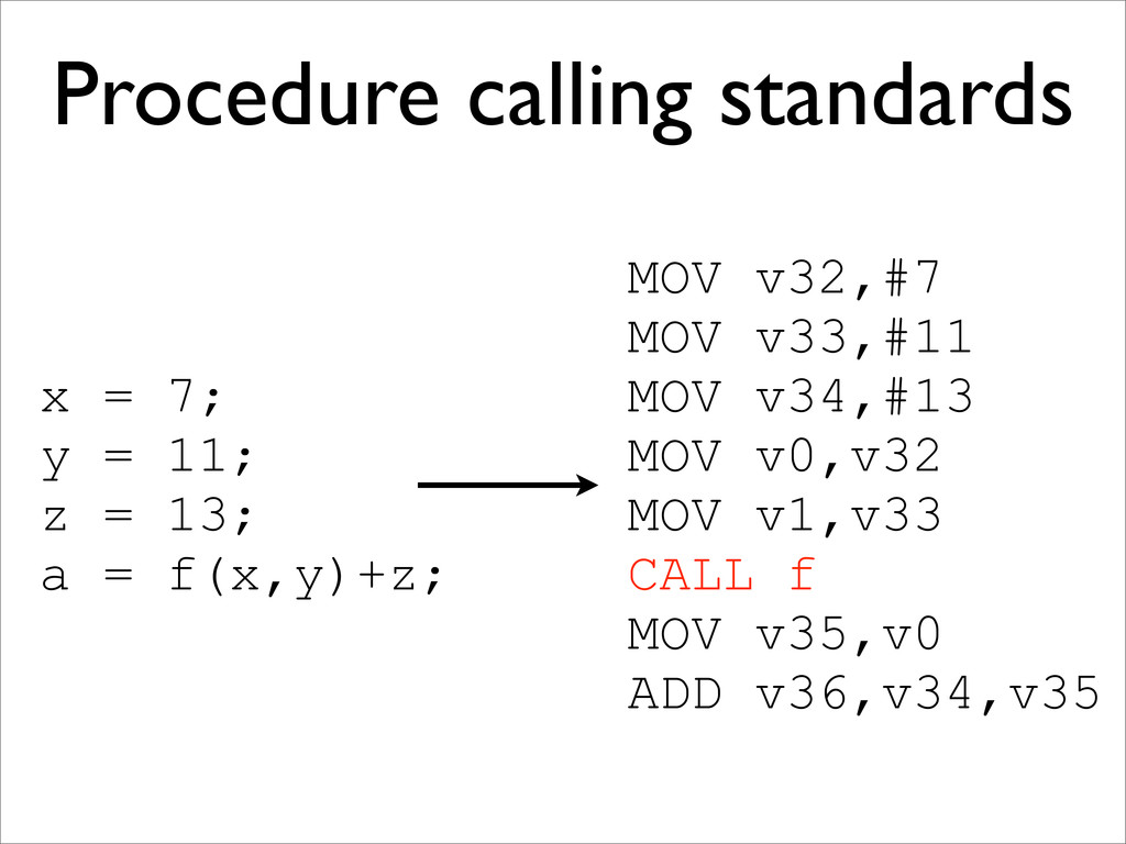
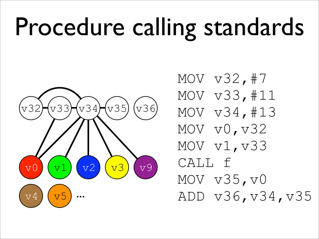
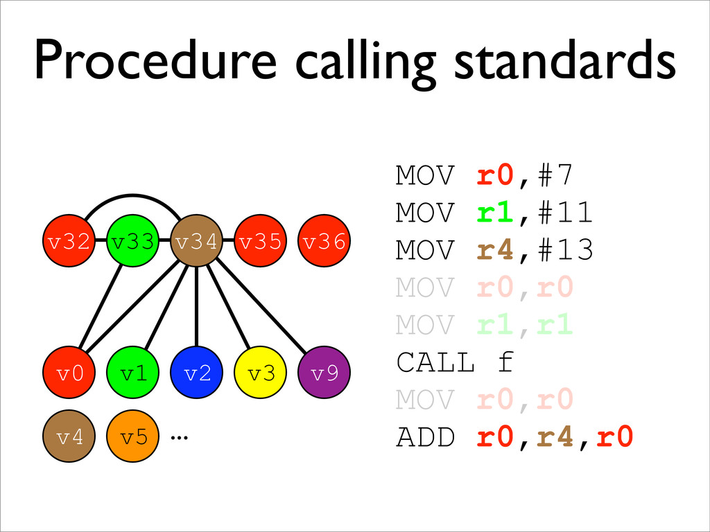
* Procedure calling standards are also handled this way