to Transport Layer Services: The main role of the transport layer is to provide the communication services directly to the application processes running on different hosts. The transport layer provides a logical communication between application processes running on different hosts. Although the application processes on different hosts are not physically connected, application processes use the logical communication provided by the transport layer to send the messages to each other. The transport layer protocols are implemented in the end systems but not in the network routers. A computer network provides more than one protocol to the network applications. For example, TCP and UDP are two transport layer protocols that provide a different set of services to the network layer. All transport layer protocols provide multiplexing/demultiplexing service. It also provides other services such as reliable data transfer, bandwidth guarantees, and delay guarantees. Each of the applications in the application layer has the ability to send a message by using TCP or UDP. The application communicates by using either of these two protocols. Both TCP and UDP will then communicate with the internet protocol in the internet layer. The applications can read and write to the transport layer. Therefore, we can say that communication is a twoway process. 2.5. The TCP: TCP is a connection-oriented protocol, which means that it first establishes the connection between the sender and receiver in the form of a handshake. After both the connections are verified, it begins transmitting packets. It makes the transmission process error-free and ensures the delivery of data. It is an important part of the communication protocols used to interconnect network devices on the internet. The whole internet system relies on this network. TCP is one of the most common protocols that ensure end-to-end delivery. It guarantees the security and integrity of the data being transmitted. It always establishes a secure connection between the sender and receiver. The transmitter is the server, and the receiver is known as the client. We can also say that the data transmission occurs between the server and client. Hence, TCP is used in most of the Sharad Institute of Technology, College of Engineering Yadrav Page 1
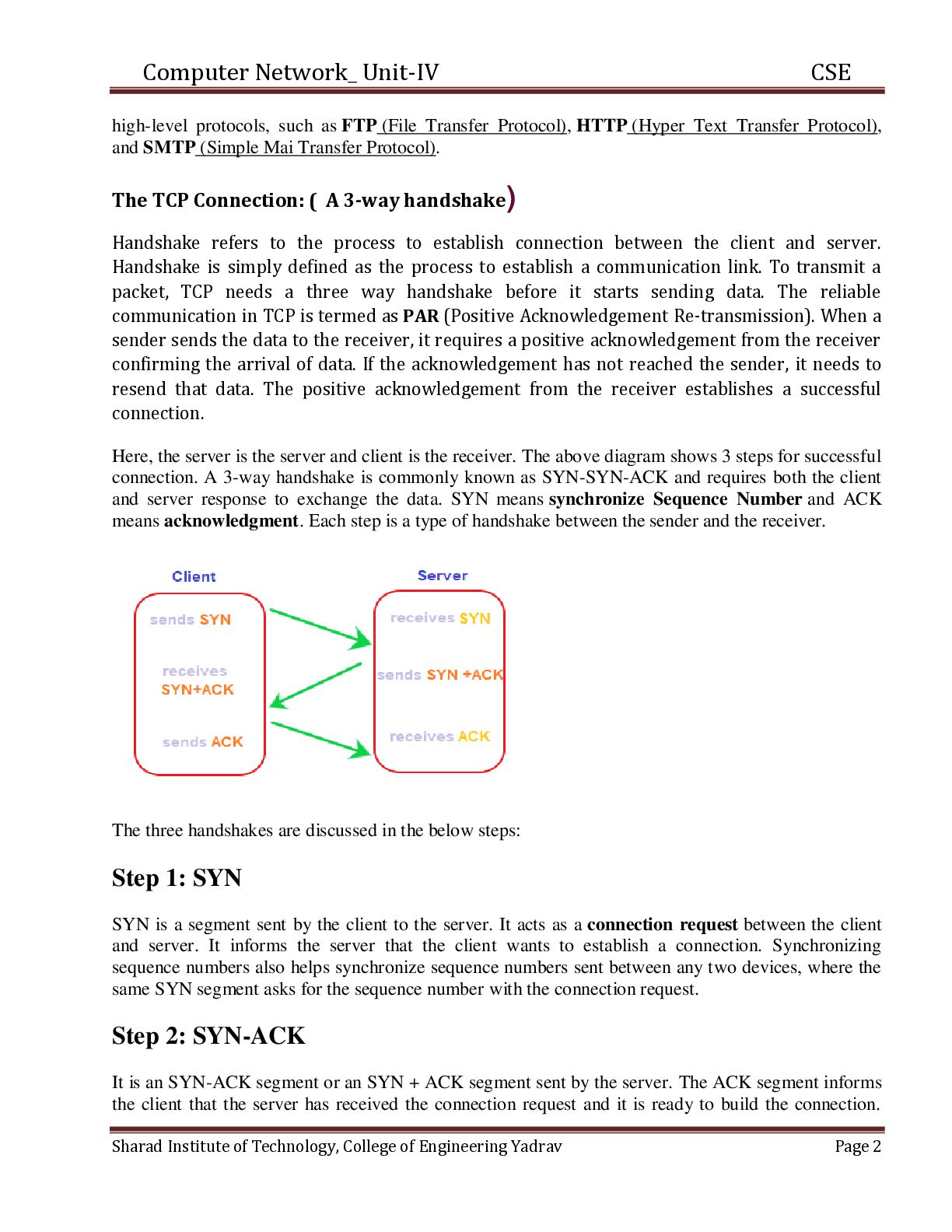
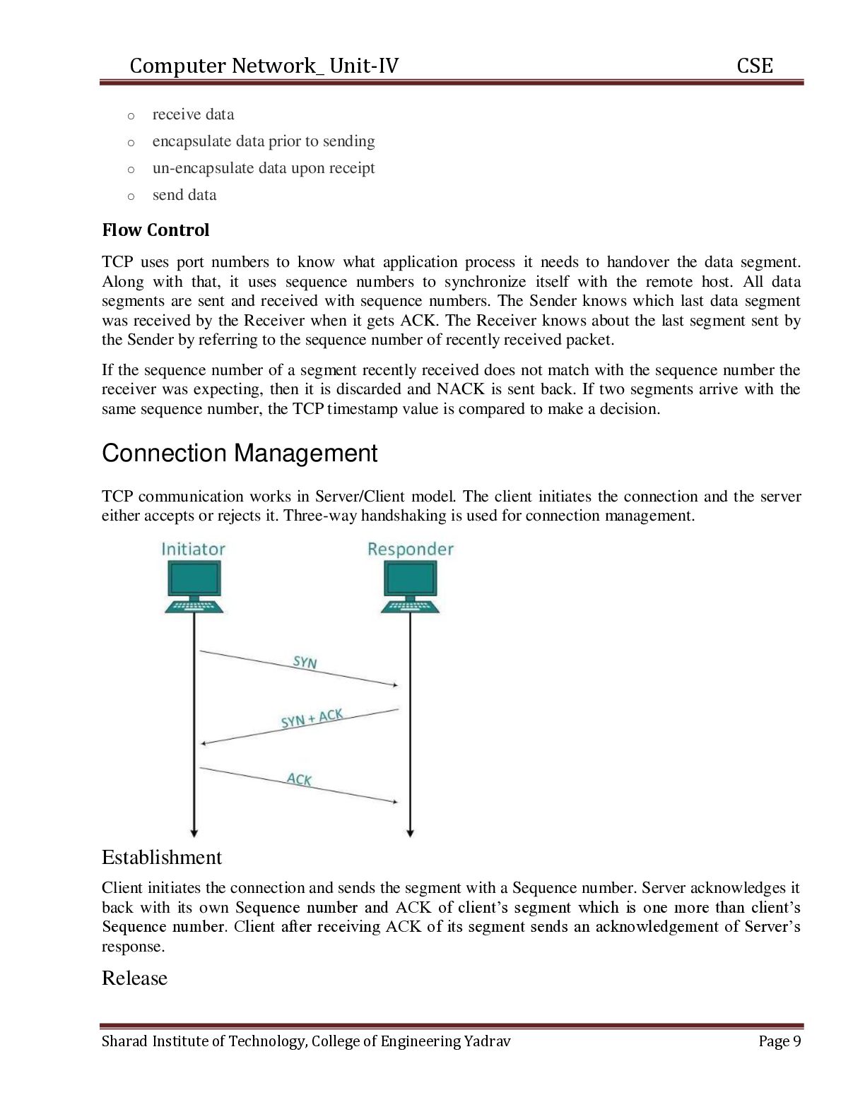
Transfer Protocol), HTTP (Hyper Text Transfer Protocol), and SMTP (Simple Mai Transfer Protocol). The TCP Connection: ( A 3-way handshake) Handshake refers to the process to establish connection between the client and server. Handshake is simply defined as the process to establish a communication link. To transmit a packet, TCP needs a three way handshake before it starts sending data. The reliable communication in TCP is termed as PAR (Positive Acknowledgement Re-transmission). When a sender sends the data to the receiver, it requires a positive acknowledgement from the receiver confirming the arrival of data. If the acknowledgement has not reached the sender, it needs to resend that data. The positive acknowledgement from the receiver establishes a successful connection. Here, the server is the server and client is the receiver. The above diagram shows 3 steps for successful connection. A 3-way handshake is commonly known as SYN-SYN-ACK and requires both the client and server response to exchange the data. SYN means synchronize Sequence Number and ACK means acknowledgment. Each step is a type of handshake between the sender and the receiver. The three handshakes are discussed in the below steps: Step 1: SYN SYN is a segment sent by the client to the server. It acts as a connection request between the client and server. It informs the server that the client wants to establish a connection. Synchronizing sequence numbers also helps synchronize sequence numbers sent between any two devices, where the same SYN segment asks for the sequence number with the connection request. Step 2: SYN-ACK It is an SYN-ACK segment or an SYN + ACK segment sent by the server. The ACK segment informs the client that the server has received the connection request and it is ready to build the connection. Sharad Institute of Technology, College of Engineering Yadrav Page 2
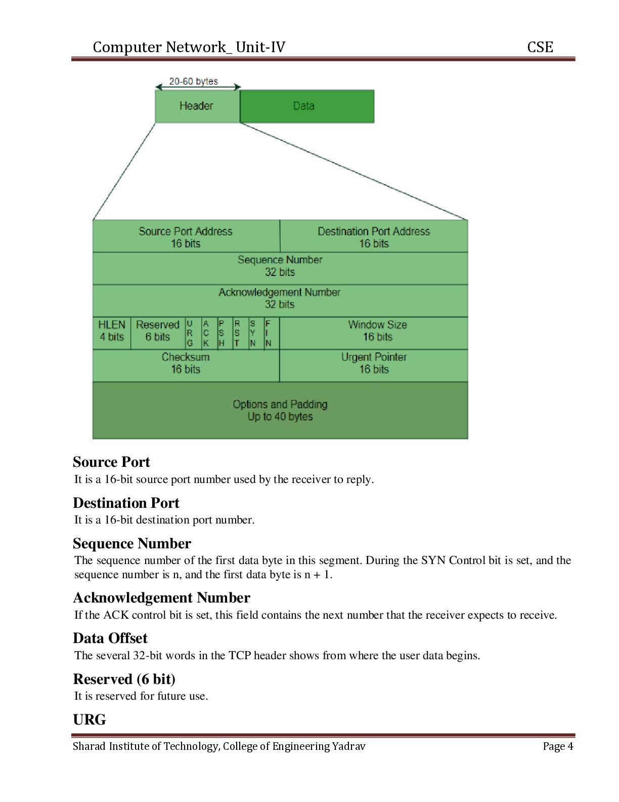
number with which the server is ready to start with the segments. Step 3: ACK ACK (Acknowledgment) is the last step before establishing a successful TCP connection between the client and server. The ACK segment is sent by the client as the response of the received ACK and SN from the server. It results in the establishment of a reliable data connection. After these three steps, the client and server are ready for the data communication process. TCP connection and termination are full-duplex, which means that the data can travel in both the directions simultaneously. TCP Segment Structure: Every TCP segment consists of a 20 byte fixed format header. Header options may follow the fixed header. With a header so that it can tag up to 65535 data bytes. The TCP header format is shown in the figure below – Sharad Institute of Technology, College of Engineering Yadrav Page 3
source port number used by the receiver to reply. Destination Port It is a 16-bit destination port number. Sequence Number The sequence number of the first data byte in this segment. During the SYN Control bit is set, and the sequence number is n, and the first data byte is n + 1. Acknowledgement Number If the ACK control bit is set, this field contains the next number that the receiver expects to receive. Data Offset The several 32-bit words in the TCP header shows from where the user data begins. Reserved (6 bit) It is reserved for future use. URG Sharad Institute of Technology, College of Engineering Yadrav Page 4
that data type is urgent or not. ACK It indicates that the acknowledgement field in a segment is significant, as discussed early. PUSH The PUSH flag is set or reset according to a data type that is sent immediately or not. RST It Resets the connection. SYN It synchronizes the sequence number. FIN This indicates no more data from the sender. Window It is used in Acknowledgement segment. It specifies the number of data bytes, beginning with the one indicated in the acknowledgement number field that the receiver is ready to accept. Checksum It is used for error detection. Options The IP datagram options provide additional punctuality. It can use several optional parameters between a TCP sender and receiver. It depends on the options used. The length of the field may vary in size, but it can't be larger than 40 bytes due to the header field's size, which is 4 bit. The most typical option is the maximum segment size MASS option. A TCP receiver communicates to the TCP sender the total length of the segment it can accept with this option. The other various options are used for flow control and congestion control, each explained in the table shown in the table. Padding Options in each may vary in size, and it may be necessary to "pad" the TCP header with zeros so that the segment ends on a 32-bit word boundary as per the standard. Data Although in some cases like acknowledgement segments with no data in the reverse direction, the variable-length field carries the application data from sender to receiver. This field, connected with the TCP header fields, constitute a TCP segment. Round Trip Time Estimation and Timeout: Sharad Institute of Technology, College of Engineering Yadrav Page 5
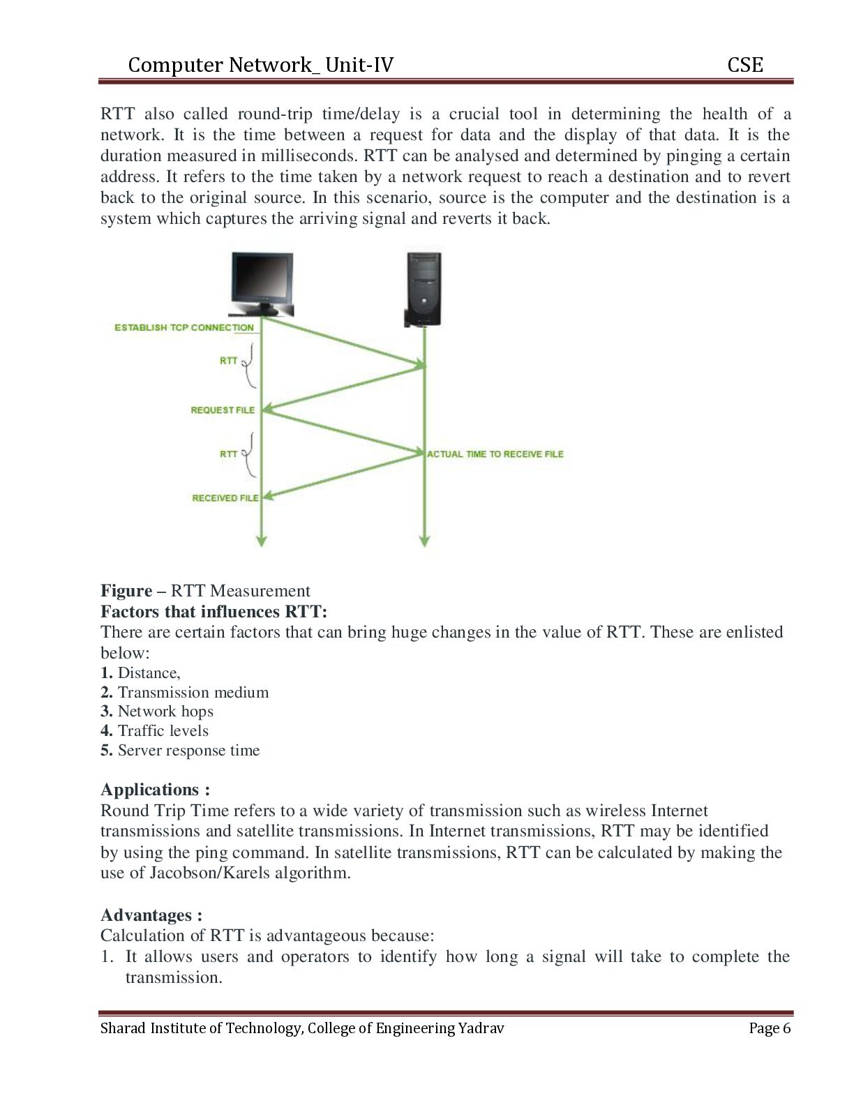
a crucial tool in determining the health of a network. It is the time between a request for data and the display of that data. It is the duration measured in milliseconds. RTT can be analysed and determined by pinging a certain address. It refers to the time taken by a network request to reach a destination and to revert back to the original source. In this scenario, source is the computer and the destination is a system which captures the arriving signal and reverts it back. Figure – RTT Measurement Factors that influences RTT: There are certain factors that can bring huge changes in the value of RTT. These are enlisted below: 1. Distance, 2. Transmission medium 3. Network hops 4. Traffic levels 5. Server response time Applications : Round Trip Time refers to a wide variety of transmission such as wireless Internet transmissions and satellite transmissions. In Internet transmissions, RTT may be identified by using the ping command. In satellite transmissions, RTT can be calculated by making the use of Jacobson/Karels algorithm. Advantages : Calculation of RTT is advantageous because: 1. It allows users and operators to identify how long a signal will take to complete the transmission. Sharad Institute of Technology, College of Engineering Yadrav Page 6
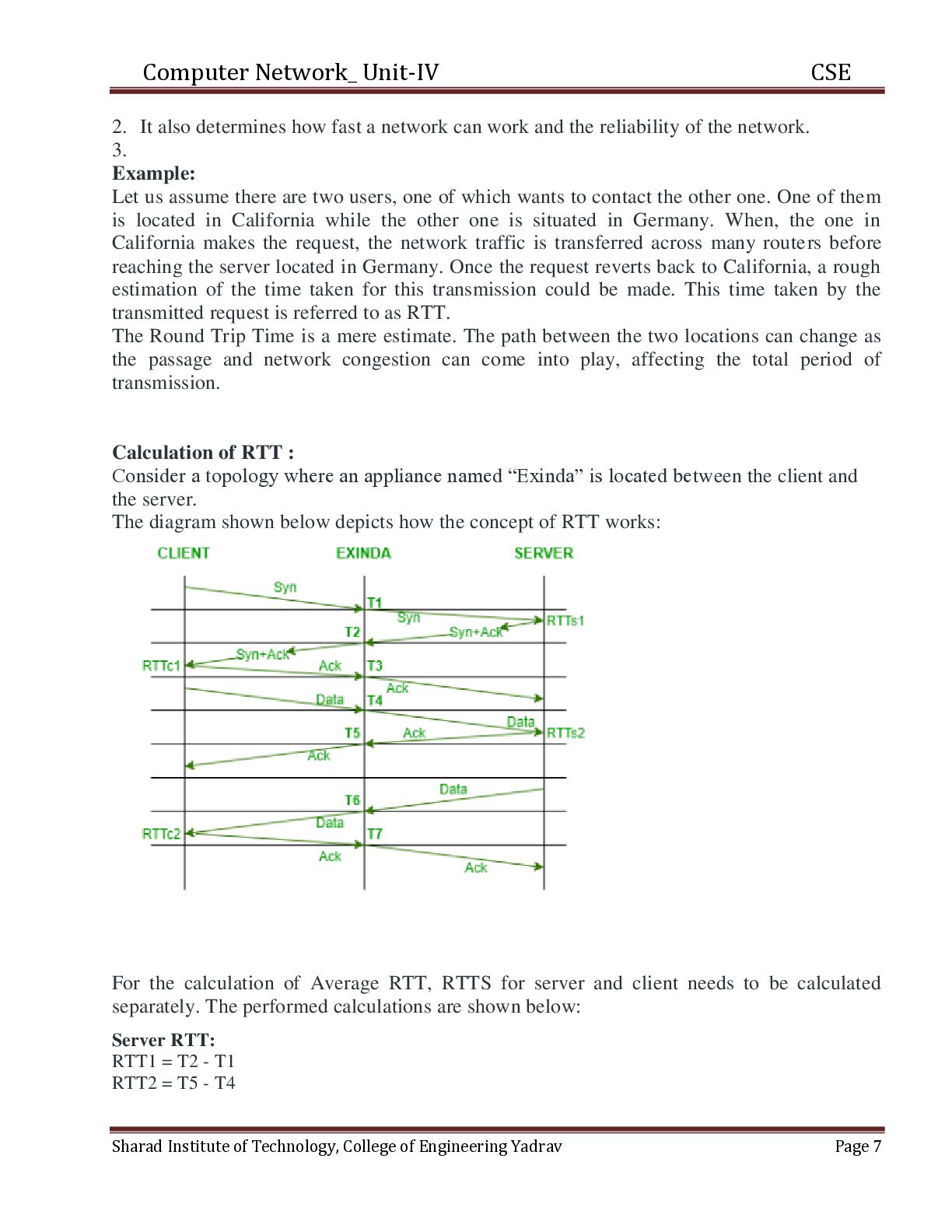
a network can work and the reliability of the network. 3. Example: Let us assume there are two users, one of which wants to contact the other one. One of them is located in California while the other one is situated in Germany. When, the one in California makes the request, the network traffic is transferred across many routers before reaching the server located in Germany. Once the request reverts back to California, a rough estimation of the time taken for this transmission could be made. This time taken by the transmitted request is referred to as RTT. The Round Trip Time is a mere estimate. The path between the two locations can change as the passage and network congestion can come into play, affecting the total period of transmission. Calculation of RTT : Consider a topology where an appliance named “Exinda” is located between the client and the server. The diagram shown below depicts how the concept of RTT works: For the calculation of Average RTT, RTTS for server and client needs to be calculated separately. The performed calculations are shown below: Server RTT: RTT1 = T2 - T1 RTT2 = T5 - T4 Sharad Institute of Technology, College of Engineering Yadrav Page 7
T2 RTT4 = T7 - T6 Average RTT: Avg Server RTT = (RTTs1 + RTTs2) / 2 Avg Client RTT = (RTTc1 + RTTc2) / 2 Avg Total RTT = Avg Server RTT + Avg Client RTT Measures to reduce RTT : A significant reduction in RTT can be made using Content Delivery Network (CDN). A CDN refers to a network of various servers, each acquiring a copy of the content on a particular website. It addresses the factors affecting RTT in the enlisted ways: 1. Points of Presence (PoP) 2. Web caching 3. Load distribution 4. Scalability 5. Tier 1 access Reliable Data Transfer: Reliable data transfer protocols (RDT, RDP) are algorithmic measures to provide assurances of the reliable transfer of data across a network that may be subject to data loss and/or corruption. RDT involves sender-side and receiver-side sequences and variables to validate, acknowledge, and retransmit data when necessary. The goal of RDT protocols is to provide network and link layer service such that application and transport layer services can make guarantees about data delivery. Reliable Data Transfer Protocols must address the two primary concerns of data loss and data corruption. In network communications, these types of errors generally occur on the physical network hardware during buffering, propagation, and transmission actions. To address these concerns, senders and receivers need a way to communicate indirectly with respect to the receipt and validation of data being transmitted. In such cases where data has been lost or corrupted, RDT protocols dictate that data should be re-transmitted. At the most basic level, this introduces another concern of duplicate data into the mix. Data loss and corruption are the two primary concerns RDT seeks to address. The concern of duplicate data only arises through actions taken to address these first two concerns. As such, considering the issues of loss and corruption is a sensible place to begin considering the underlying function of RDT. Four Functions of Reliable Data Transfer Implementing RDP as a transport layer service requires several moving parts amidst several checkpoints, so to speak. These “checkpoints” are points during data transmission where the following actions may occur: Sharad Institute of Technology, College of Engineering Yadrav Page 8
to sending o un-encapsulate data upon receipt o send data CSE Flow Control TCP uses port numbers to know what application process it needs to handover the data segment. Along with that, it uses sequence numbers to synchronize itself with the remote host. All data segments are sent and received with sequence numbers. The Sender knows which last data segment was received by the Receiver when it gets ACK. The Receiver knows about the last segment sent by the Sender by referring to the sequence number of recently received packet. If the sequence number of a segment recently received does not match with the sequence number the receiver was expecting, then it is discarded and NACK is sent back. If two segments arrive with the same sequence number, the TCP timestamp value is compared to make a decision. Connection Management TCP communication works in Server/Client model. The client initiates the connection and the server either accepts or rejects it. Three-way handshaking is used for connection management. Establishment Client initiates the connection and sends the segment with a Sequence number. Server acknowledges it back with its own Sequence number and ACK of client’s segment which is one more than client’s Sequence number. Client after receiving ACK of its segment sends an acknowledgement of Server’s response. Release Sharad Institute of Technology, College of Engineering Yadrav Page 9
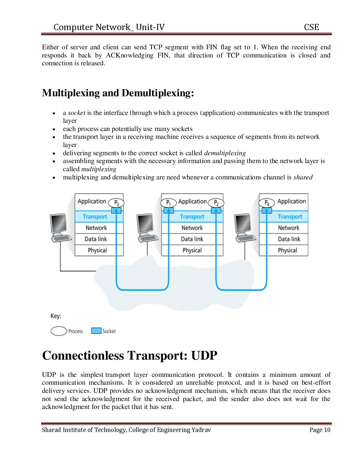
send TCP segment with FIN flag set to 1. When the receiving end responds it back by ACKnowledging FIN, that direction of TCP communication is closed and connection is released. Multiplexing and Demultiplexing: a socket is the interface through which a process (application) communicates with the transport layer each process can potentially use many sockets the transport layer in a receiving machine receives a sequence of segments from its network layer delivering segments to the correct socket is called demultiplexing assembling segments with the necessary information and passing them to the network layer is called multiplexing multiplexing and demultiplexing are need whenever a communications channel is shared Connectionless Transport: UDP UDP is the simplest transport layer communication protocol. It contains a minimum amount of communication mechanisms. It is considered an unreliable protocol, and it is based on best-effort delivery services. UDP provides no acknowledgment mechanism, which means that the receiver does not send the acknowledgment for the received packet, and the sender also does not wait for the acknowledgment for the packet that it has sent. Sharad Institute of Technology, College of Engineering Yadrav Page 10
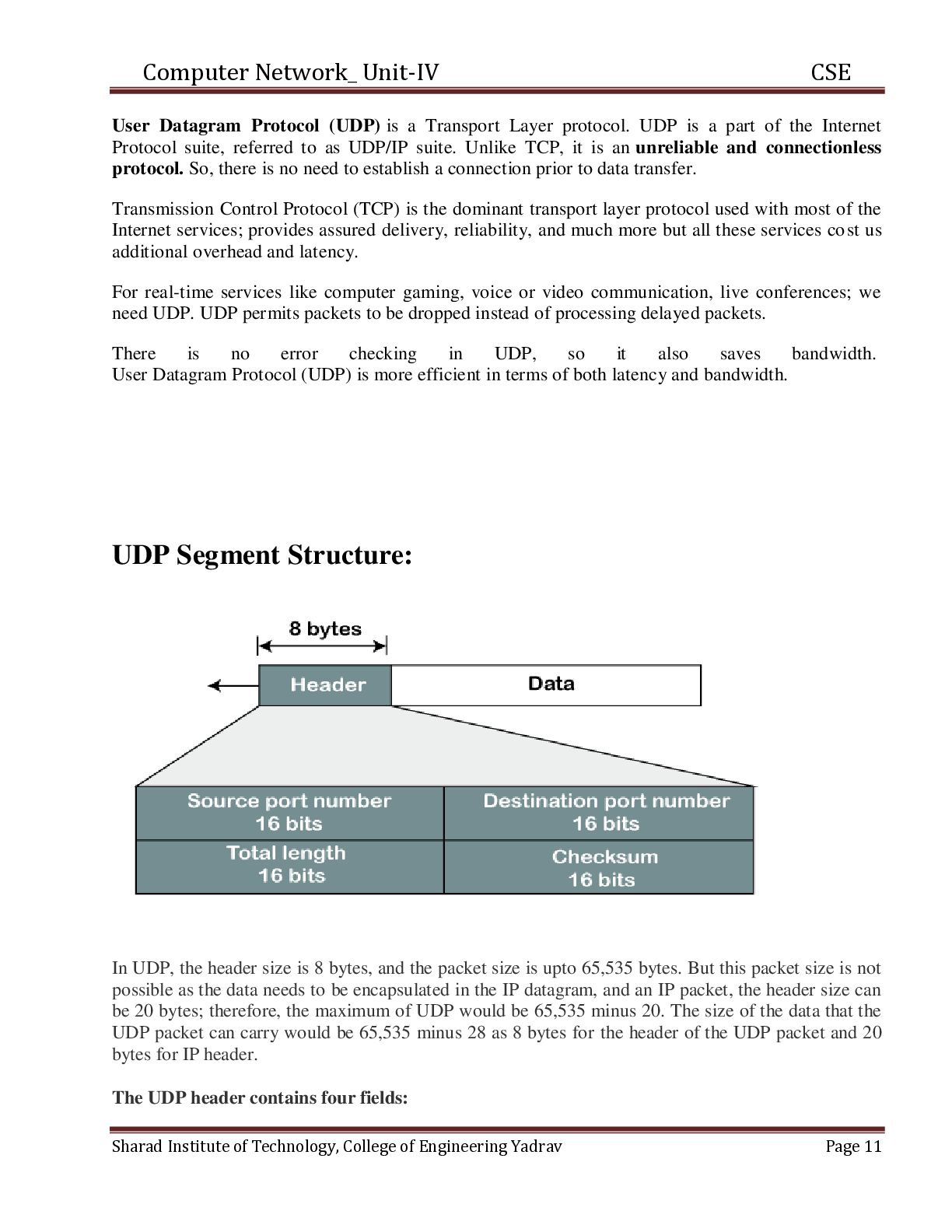
Transport Layer protocol. UDP is a part of the Internet Protocol suite, referred to as UDP/IP suite. Unlike TCP, it is an unreliable and connectionless protocol. So, there is no need to establish a connection prior to data transfer. Transmission Control Protocol (TCP) is the dominant transport layer protocol used with most of the Internet services; provides assured delivery, reliability, and much more but all these services co st us additional overhead and latency. For real-time services like computer gaming, voice or video communication, live conferences; we need UDP. UDP permits packets to be dropped instead of processing delayed packets. There is no error checking in UDP, so it also saves bandwidth. User Datagram Protocol (UDP) is more efficient in terms of both latency and bandwidth. UDP Segment Structure: In UDP, the header size is 8 bytes, and the packet size is upto 65,535 bytes. But this packet size is not possible as the data needs to be encapsulated in the IP datagram, and an IP packet, the header size can be 20 bytes; therefore, the maximum of UDP would be 65,535 minus 20. The size of the data that the UDP packet can carry would be 65,535 minus 28 as 8 bytes for the header of the UDP packet and 20 bytes for IP header. The UDP header contains four fields: Sharad Institute of Technology, College of Engineering Yadrav Page 11
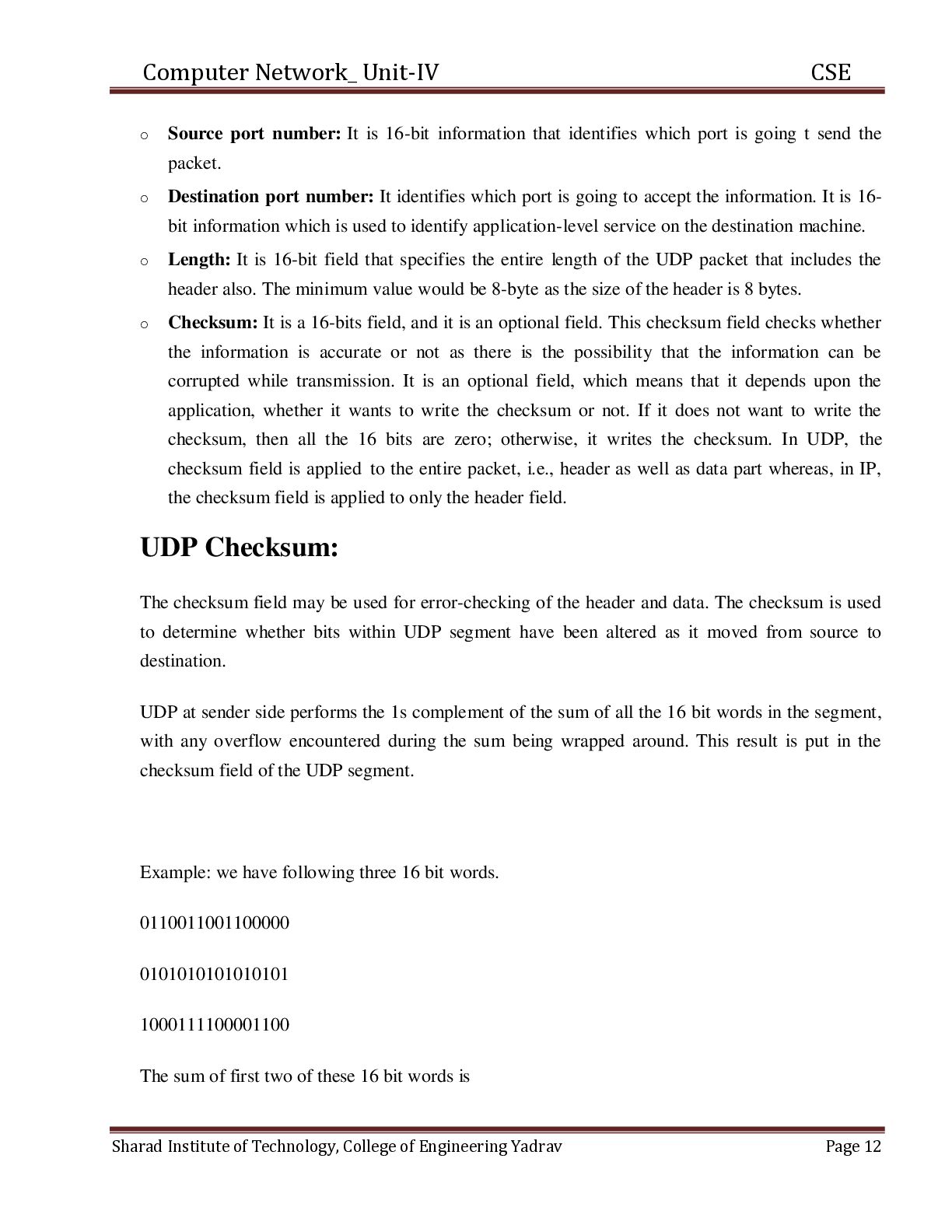
16-bit information that identifies which port is going t send the packet. o Destination port number: It identifies which port is going to accept the information. It is 16bit information which is used to identify application-level service on the destination machine. o Length: It is 16-bit field that specifies the entire length of the UDP packet that includes the header also. The minimum value would be 8-byte as the size of the header is 8 bytes. o Checksum: It is a 16-bits field, and it is an optional field. This checksum field checks whether the information is accurate or not as there is the possibility that the information can be corrupted while transmission. It is an optional field, which means that it depends upon the application, whether it wants to write the checksum or not. If it does not want to write the checksum, then all the 16 bits are zero; otherwise, it writes the checksum. In UDP, the checksum field is applied to the entire packet, i.e., header as well as data part whereas, in IP, the checksum field is applied to only the header field. UDP Checksum: The checksum field may be used for error-checking of the header and data. The checksum is used to determine whether bits within UDP segment have been altered as it moved from source to destination. UDP at sender side performs the 1s complement of the sum of all the 16 bit words in the segment, with any overflow encountered during the sum being wrapped around. This result is put in the checksum field of the UDP segment. Example: we have following three 16 bit words. 0110011001100000 0101010101010101 1000111100001100 The sum of first two of these 16 bit words is Sharad Institute of Technology, College of Engineering Yadrav Page 12
word to the above sum gives 1011101110110101 1000111100001100 0100101011000010 This last addition had overflow, which was wrapped around. The 1s complement is obtaion by converting all the 0s to 1s and converting all the 1s to 0s. Thus the 1s complement of the sum 0100101011000010 is 101101100111101, which becomes the checksum. At the receiver, all four 16 bit words are added including the checksum. If no error introduced into the packet, then clearly the sum at the receiver will be 1111111111111111. If one of the bits is a zero, then we know that errors have been introduced into the packet. Pipelined Reliable data transfer Protocol: In a pipelined reliable data transfer protocol, the sender can start sending a second data packet before the sender receives the acknowledgment for the first data packet. Thus, if the sender needs to send several packets, then the time until the last of the packets is sent will be shorter with a pipelined protocol. Thus, a pipelined protocol can have better performance than the Stop-and-Wait protocol. It is possible to measure the extent to which a pipelined protocol has better performance that Stop-and-Wait. This is called measuring the utilization of the connection or link between the sender and the receiver The sender can keep on sending packets even if the acknowledgements for the earlier packets have not yet returned. Thus, it takes less time to send a sequence of packets. The applet assumes that the sender can send at most three packets at any one time and wants to send four packets. Sharad Institute of Technology, College of Engineering Yadrav Page 13
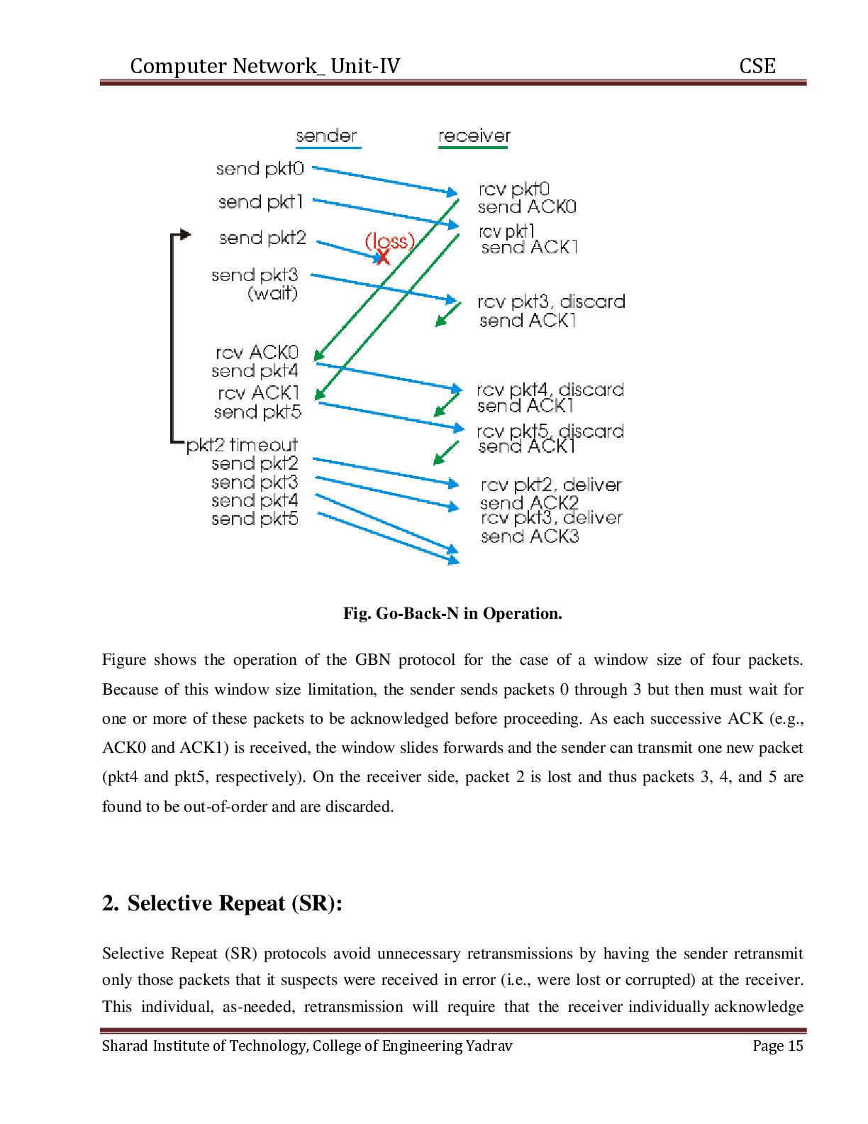
protocol is used, just as they can occur when the stop-and-wait protocol is used. The same two cases exist. 1) a lost or corrupted data packet or 2) ) a lost or corrupted acknowledgment packet. There are two approaches to this problem. In one approach, called Go-Back-N, the sender retransmits all the data packets it had sent since the lost or corrupted data packet. In the second approach, called Selective Repeat, the sender just retransmits the lost or corrupted data packet. Selective Repeat causes fewer packets to be retransmitted, but requires more overhead on the part of the receiver. 1. Go-Back-N: In a Go-Back-N (GBN) protocol, the sender is allowed to transmit multiple packets (when available) without waiting for an acknowledgment, but is constrained to have no more than some maximum allowable number, N, of unacknowledged packets in the pipeline. Sharad Institute of Technology, College of Engineering Yadrav Page 14
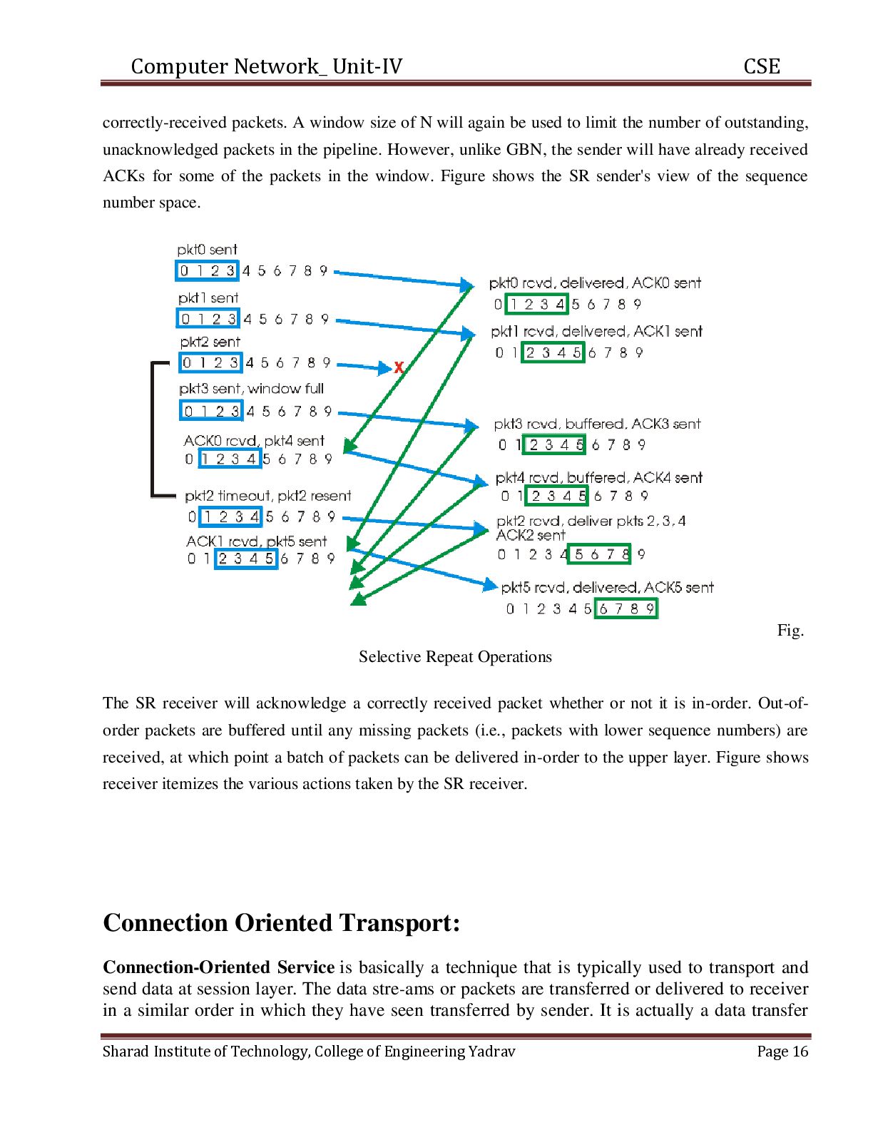
the operation of the GBN protocol for the case of a window size of four packets. Because of this window size limitation, the sender sends packets 0 through 3 but then must wait for one or more of these packets to be acknowledged before proceeding. As each successive ACK (e.g., ACK0 and ACK1) is received, the window slides forwards and the sender can transmit one new packet (pkt4 and pkt5, respectively). On the receiver side, packet 2 is lost and thus packets 3, 4, and 5 are found to be out-of-order and are discarded. 2. Selective Repeat (SR): Selective Repeat (SR) protocols avoid unnecessary retransmissions by having the sender retransmit only those packets that it suspects were received in error (i.e., were lost or corrupted) at the receiver. This individual, as-needed, retransmission will require that the receiver individually acknowledge Sharad Institute of Technology, College of Engineering Yadrav Page 15
N will again be used to limit the number of outstanding, unacknowledged packets in the pipeline. However, unlike GBN, the sender will have already received ACKs for some of the packets in the window. Figure shows the SR sender's view of the sequence number space. Fig. Selective Repeat Operations The SR receiver will acknowledge a correctly received packet whether or not it is in-order. Out-oforder packets are buffered until any missing packets (i.e., packets with lower sequence numbers) are received, at which point a batch of packets can be delivered in-order to the upper layer. Figure shows receiver itemizes the various actions taken by the SR receiver. Connection Oriented Transport: Connection-Oriented Service is basically a technique that is typically used to transport and send data at session layer. The data stre-ams or packets are transferred or delivered to receiver in a similar order in which they have seen transferred by sender. It is actually a data transfer Sharad Institute of Technology, College of Engineering Yadrav Page 16
in a different network, that is designed and developed after telephone system. Whenever a network implements this service, it sends or transfers data or message from sender or source to receiver or destination in correct order and manner. This connection service is generally provided by protocols of both network layer (signifies different path for various data packets that belongs to same message) as well as transport layer (use to exhibits independence among packets rather than different paths that various packets belong to same message will follow). Operations : There is a sequence of operations that are needed to b followed by users. These operations are given below : 1. Establishing Connection – It generally requires a session connection to be established just before any data is transported or sent with a direct physical connection among sessions. 1. Transferring Data or Message – When this session connection is established, then we transfer or send message or data. 2. Releasing the Connection – After sending or transferring data, we release connection. Advantages : It kindly support for quality of service is an easy way. This connection is more reliable than connectionless service. Long and large messages can be divided into various smaller messages so that it can fit inside packets. Problems or issues that are related to duplicate data packets are made less severe. Disadvantages : In this connection, cost is fixed no matter how traffic is. It is necessary to have resource allocation before communication. If any route or path failures or network congestions arise, there is no alternative way available to continue communication. Sharad Institute of Technology, College of Engineering Yadrav Page 17


 pawan_pharm
 auctria
 juanmartin2026
 signer
 cbtlibrary
 akiraasano
 hiola
 mutomasa
 ainischool
 bvr7352
 addyosmani
 jlugia
 eileencodes
 orderedlist
 konakalab
 samanthasiow
 csswizardry
 ipullrank
 takai
 sabderemane
 maggiecrowley
 eitanlees