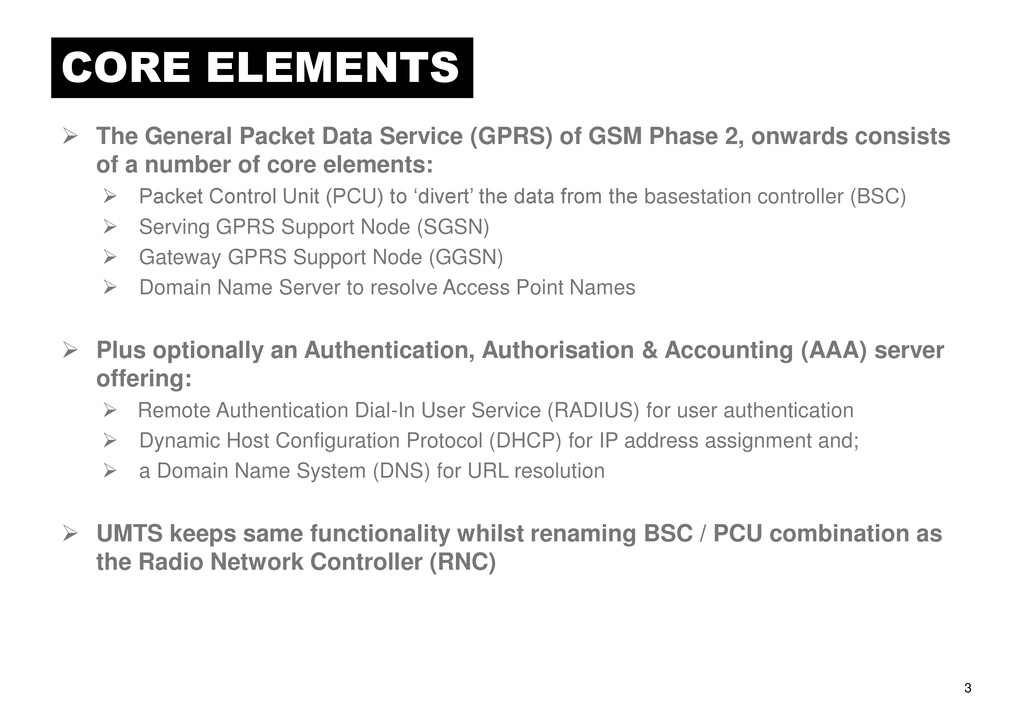
of GSM Phase 2, onwards consists of a number of core elements: Packet Control Unit (PCU) to „divert‟ the data from the basestation controller (BSC) Serving GPRS Support Node (SGSN) Gateway GPRS Support Node (GGSN) Domain Name Server to resolve Access Point Names Plus optionally an Authentication, Authorisation & Accounting (AAA) server offering: Remote Authentication Dial-In User Service (RADIUS) for user authentication Dynamic Host Configuration Protocol (DHCP) for IP address assignment and; a Domain Name System (DNS) for URL resolution UMTS keeps same functionality whilst renaming BSC / PCU combination as the Radio Network Controller (RNC)
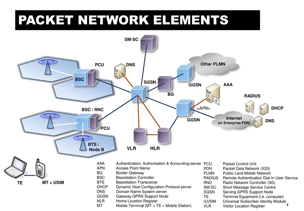
APN Access Point Name BG Border Gateway BSC Basestation Controller BTS Basestation Transceiver DHCP Dynamic Host Configuration Protocol server DNS Domain Name System server GGSN Gateway GPRS Support Node HLR Home Location Register MT Mobile Terminal (MT + TE = Mobile Station) BSC BTS / Node B PCU PCU BSC / RNC BG Other PLMN SM-SC GGSN SGSN HLR VLR DNS MT + USIM TE PCU Packet Control Unit PDN Packet Data Network (X25) PLMN Public Land Mobile Network RADIUS Remote Authentication Dial-In User Service RNC Radio Network Controller (3G) SM-SC Short Message Service Centre SGSN Serving GPRS Support Node TE Terminal Equipment (i.e. computer) (U)SIM Universal Subscriber Identity Module VLR Visitor Location Register Internet (or Enterprise PDN) GGSN DHCP AAA RADIUS DNS <APN>
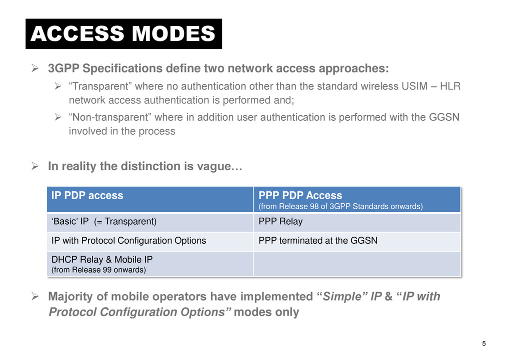
approaches: “Transparent” where no authentication other than the standard wireless USIM – HLR network access authentication is performed and; “Non-transparent” where in addition user authentication is performed with the GGSN involved in the process In reality the distinction is vague… Majority of mobile operators have implemented “Simple” IP & “IP with Protocol Configuration Options” modes only IP PDP access PPP PDP Access (from Release 98 of 3GPP Standards onwards) „Basic‟ IP (= Transparent) PPP Relay IP with Protocol Configuration Options PPP terminated at the GGSN DHCP Relay & Mobile IP (from Release 99 onwards)
mobile operator network assigns a static or dynamic IP address to the terminal or application. This access mode may still use an AAA server to perform the IMSI or MS-ISDN authentication and subsequent IP address assignment (note: static IP address assignment is necessary if network-initiated PDP context activation is required). The limitation of this approach is that any external network must trust the wireless network operator to provide user authentication. There is nothing to prevent an individual getting hold of a terminal and accessing the network associated with the APN as no password or two- factor authentication (password + token) is used. This access mode is most suitable for services that require minimum interaction between the user and the terminal to set up connectivity, and is the default access mode for most web browsing applications, especially on Smartphones. Of course a Virtual Private Network (VPN) can be created once a „public‟ IP address has been assigned to the terminal to provide end- to-end authentication and security.
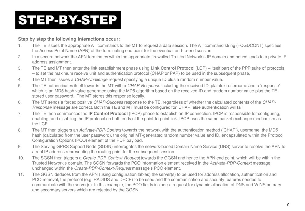
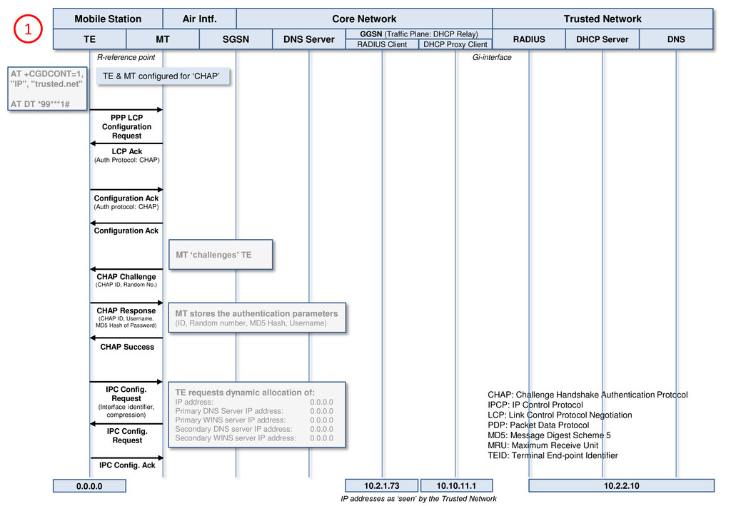
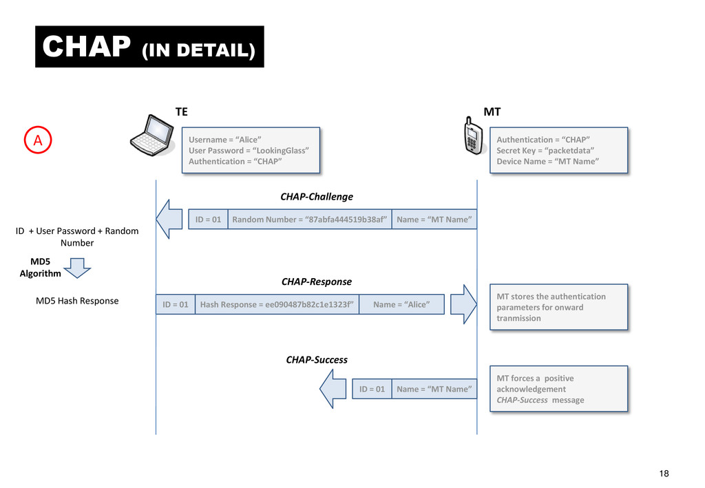
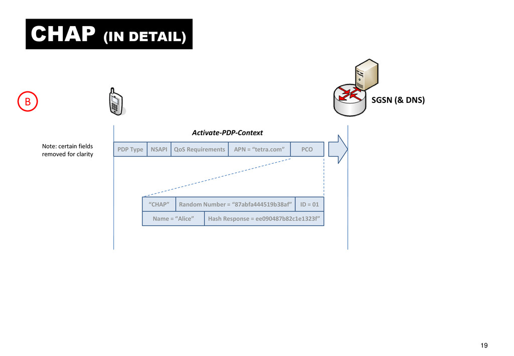
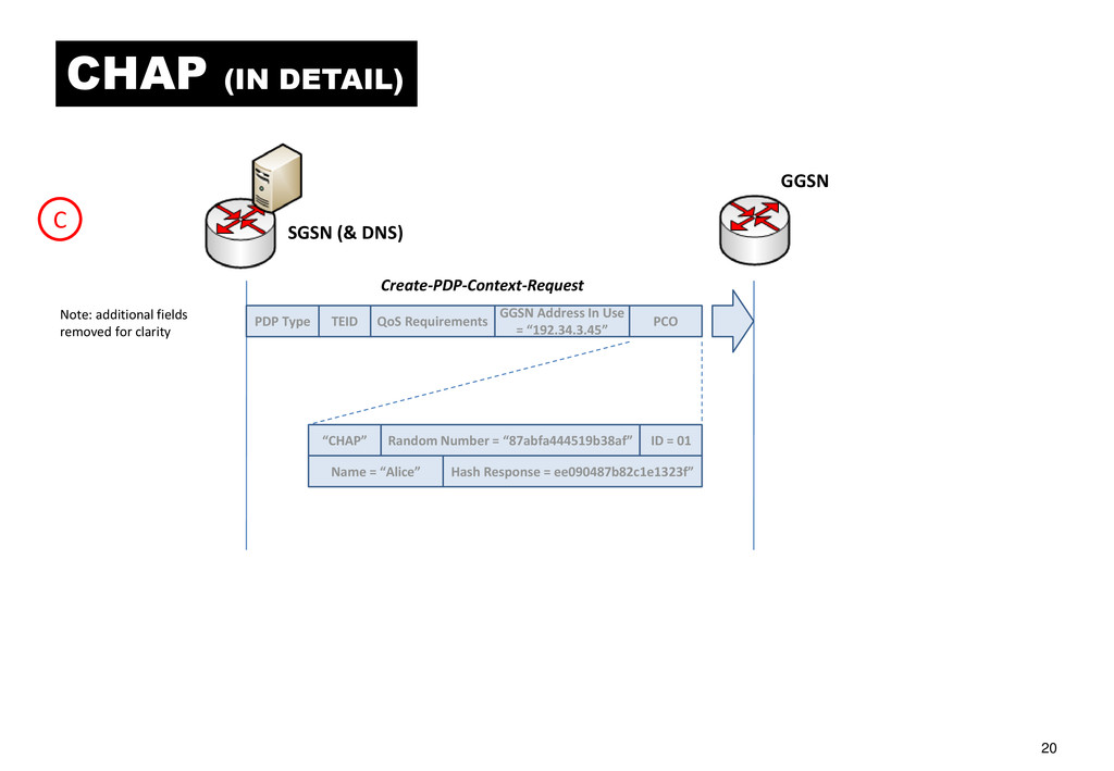
The TE issues the appropriate AT commands to the MT to request a data session. The AT command string (+CGDCONT) specifies the Access Point Name (APN) of the terminating end point for the eventual end-to-end session. 2. In a secure network the APN terminates within the appropriate firewalled Trusted Network‟s IP domain and hence leads to a private IP address assignment. 3. The TE and MT then enter the link establishment phase using Link Control Protocol (LCP) – itself part of the PPP suite of protocols – to set the maximum receive unit and authentication protocol (CHAP or PAP) to be used in the subsequent phase. 4. The MT then issues a CHAP-Challenge request specifying a unique ID plus a random number value. 5. The TE authenticates itself towards the MT with a CHAP-Response including the received ID, plaintext username and a „response‟ which is an MD5 hash value generated using the MD5 algorithm based on the received ID and random number value plus the TE- stored user password.. The MT stores this response locally. 6. The MT sends a forced positive CHAP-Success response to the TE, regardless of whether the calculated contents of the CHAP- Response message are correct. Both the TE and MT must be configured for „CHAP‟ else authentication will fail. 7. The TE then commences the IP Control Protocol (IPCP) phase to establish an IP connection. IPCP is responsible for configuring, enabling, and disabling the IP protocol on both ends of the point-to-point link. IPCP uses the same packet exchange mechanism as the LCP. 8. The MT then triggers an Activate-PDP-Context towards the network with the authentication method („CHAP‟), username, the MD5 hash (calculated from the user password), the original MT-generated random number value and ID, encapsulated within the Protocol Configuration Options (PCO) element of the PDP payload. 9. The Serving GPRS Support Node (SGSN) interrogates the network-based Domain Name Service (DNS) server to resolve the APN to a real IP address representing the routing point for the subsequent session. 10. The SGSN then triggers a Create-PDP-Context-Request towards the GGSN and hence the APN end point, which will be within the Trusted Network‟s domain. The SGSN forwards the PCO information element received in the Activate-PDP-Context message unchanged within the Create-PDP-Context-Request message‟s PCO element. 11. The GGSN deduces from the APN (using configuration tables) the server(s) to be used for address allocation, authentication and PCO retrieval, the protocol (e.g. RADIUS and DHCP) to be used and the communication and security features needed to communicate with the server(s). In this example, the PCO fields include a request for dynamic allocation of DNS and WINS primary and secondary servers which are rejected by the GGSN.
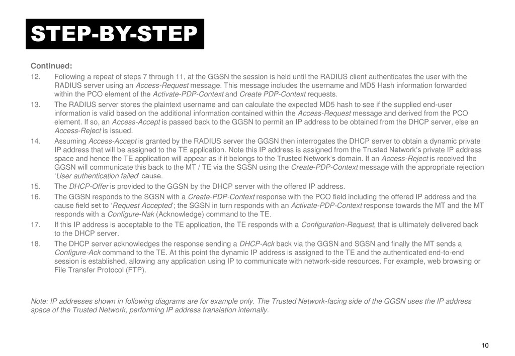
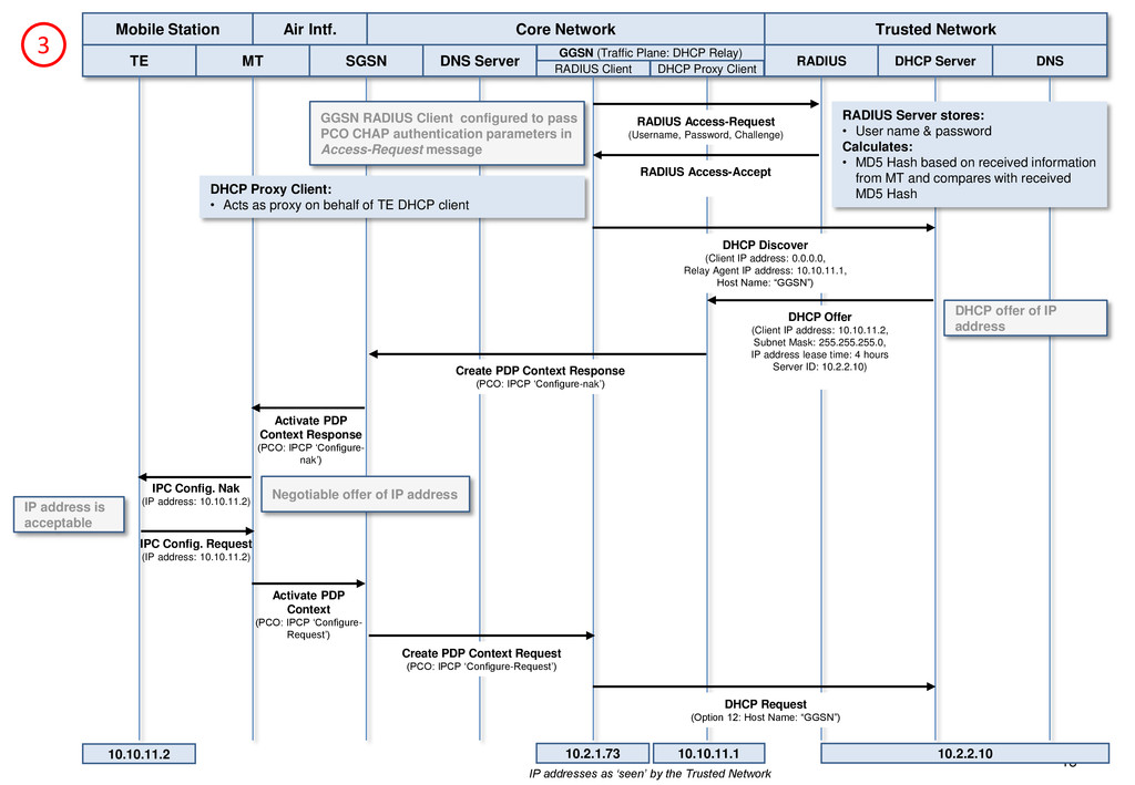
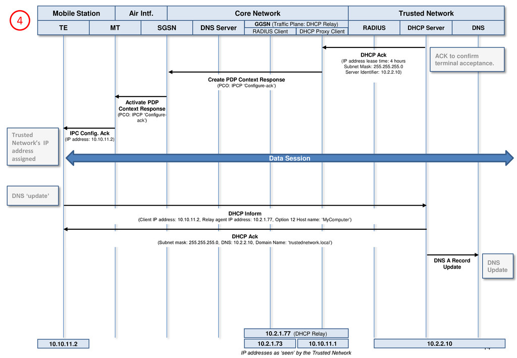
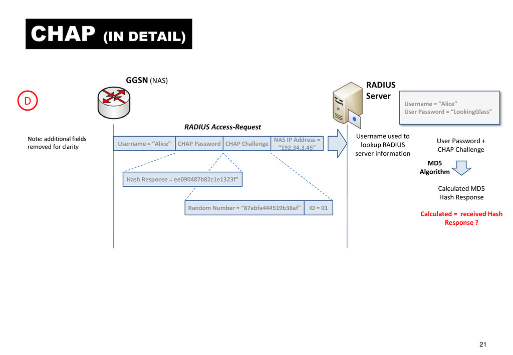
through 11, at the GGSN the session is held until the RADIUS client authenticates the user with the RADIUS server using an Access-Request message. This message includes the username and MD5 Hash information forwarded within the PCO element of the Activate-PDP-Context and Create PDP-Context requests. 13. The RADIUS server stores the plaintext username and can calculate the expected MD5 hash to see if the supplied end-user information is valid based on the additional information contained within the Access-Request message and derived from the PCO element. If so, an Access-Accept is passed back to the GGSN to permit an IP address to be obtained from the DHCP server, else an Access-Reject is issued. 14. Assuming Access-Accept is granted by the RADIUS server the GGSN then interrogates the DHCP server to obtain a dynamic private IP address that will be assigned to the TE application. Note this IP address is assigned from the Trusted Network‟s private IP address space and hence the TE application will appear as if it belongs to the Trusted Network‟s domain. If an Access-Reject is received the GGSN will communicate this back to the MT / TE via the SGSN using the Create-PDP-Context message with the appropriate rejection „User authentication failed‟ cause. 15. The DHCP-Offer is provided to the GGSN by the DHCP server with the offered IP address. 16. The GGSN responds to the SGSN with a Create-PDP-Context response with the PCO field including the offered IP address and the cause field set to „Request Accepted‟; the SGSN in turn responds with an Activate-PDP-Context response towards the MT and the MT responds with a Configure-Nak (Acknowledge) command to the TE. 17. If this IP address is acceptable to the TE application, the TE responds with a Configuration-Request, that is ultimately delivered back to the DHCP server. 18. The DHCP server acknowledges the response sending a DHCP-Ack back via the GGSN and SGSN and finally the MT sends a Configure-Ack command to the TE. At this point the dynamic IP address is assigned to the TE and the authenticated end-to-end session is established, allowing any application using IP to communicate with network-side resources. For example, web browsing or File Transfer Protocol (FTP). Note: IP addresses shown in following diagrams are for example only. The Trusted Network-facing side of the GGSN uses the IP address space of the Trusted Network, performing IP address translation internally.
Link Control Protocol Negotiation PDP: Packet Data Protocol MD5: Message Digest Scheme 5 MRU: Maximum Receive Unit TEID: Terminal End-point Identifier TE MT SGSN RADIUS Client RADIUS DHCP Server Mobile Station Core Network Trusted Network DNS Server Air Intf. DHCP Proxy Client DNS GGSN (Traffic Plane: DHCP Relay) AT +CGDCONT=1, "IP", "trusted.net" AT DT *99***1# PPP LCP Configuration Request LCP Ack (Auth Protocol: CHAP) Configuration Ack (Auth protocol: CHAP) Configuration Ack MT stores the authentication parameters (ID, Random number, MD5 Hash, Username) CHAP Challenge (CHAP ID, Random No.) CHAP Response (CHAP ID, Username, MD5 Hash of Password) CHAP Success MT ‘challenges’ TE TE requests dynamic allocation of: IP address: 0.0.0.0 Primary DNS Server IP address: 0.0.0.0 Primary WINS server IP address: 0.0.0.0 Secondary DNS server IP address: 0.0.0.0 Secondary WINS server IP address: 0.0.0.0 IPC Config. Request (Interface identifier, compression) IPC Config. Request IPC Config. Ack TE & MT configured for „CHAP‟ 1 10.2.2.10 10.10.11.1 10.2.1.73 0.0.0.0 IP addresses as ‘seen’ by the Trusted Network R-reference point Gi-interface
LCP: Link Control Protocol Negotiation PDP: Packet Data Protocol MD5: Message Digest Scheme 5 MRU: Maximum Receive Unit TEID: Terminal End-point Identifier TE MT SGSN RADIUS Client RADIUS DHCP Server Mobile Station Core Network Trusted Network DNS Server Air Intf. DHCP Proxy Client DNS GGSN (Traffic Plane: DHCP Relay) GGSN performs: • APN to IP address translation via Core Network DNS • Check on allowable PCO IE options and hence: • Determination of static vs dynamic allocation of IP addresses • Allocation of RADIUS Client or RADIUS Client & DHCP • Translates the PCO, DHCP options and RADIUS attributes Activate PDP Context (APN, QoS, PDP-Type, NSAPI, PCO) Protocol Configuration Options (PCO) information element: • CHAP information: Username + Random number + MD5 Hash • IPCP Configure-Request information DNS Query (APN) DNS Response (GGSN IP Address) Create PDP Context Request (APN, QoS, PDP-Type, TEID, PCO) 2 Create PDP Context Response (PCO: IPCP „Configure-reject‟) Activate PDP Context Response (PCO: IPCP „Configure- reject‟) IPCP Config Reject (No DNS / DHCP) IPC Config. Request (Interface identifier, compression) Reject: Client can only request IP address TE (client) requests dynamic allocation: IP address: 0.0.0.0 Activate PDP Context (APN, QoS, PDP-Type, NSAPI, PCO) Create PDP Context Request (APN, QoS, PDP-Type, TEID, PCO) 10.2.2.10 10.10.11.1 10.2.1.73 0.0.0.0 IP addresses as ‘seen’ by the Trusted Network
Station Core Network Trusted Network DNS Server Air Intf. DHCP Proxy Client DNS GGSN (Traffic Plane: DHCP Relay) 3 GGSN RADIUS Client configured to pass PCO CHAP authentication parameters in Access-Request message RADIUS Access-Request (Username, Password, Challenge) RADIUS Access-Accept DHCP offer of IP address DHCP Discover (Client IP address: 0.0.0.0, Relay Agent IP address: 10.10.11.1, Host Name: “GGSN”) DHCP Offer (Client IP address: 10.10.11.2, Subnet Mask: 255.255.255.0, IP address lease time: 4 hours Server ID: 10.2.2.10) 10.2.2.10 10.10.11.1 10.2.1.73 Create PDP Context Response (PCO: IPCP „Configure-nak‟) Negotiable offer of IP address IPC Config. Nak (IP address: 10.10.11.2) IP address is acceptable Activate PDP Context Response (PCO: IPCP „Configure- nak‟) IPC Config. Request (IP address: 10.10.11.2) Activate PDP Context (PCO: IPCP „Configure- Request‟) Create PDP Context Request (PCO: IPCP „Configure-Request‟) DHCP Request (Option 12: Host Name: “GGSN”) DHCP Proxy Client: • Acts as proxy on behalf of TE DHCP client RADIUS Server stores: • User name & password Calculates: • MD5 Hash based on received information from MT and compares with received MD5 Hash 10.10.11.2 IP addresses as ‘seen’ by the Trusted Network
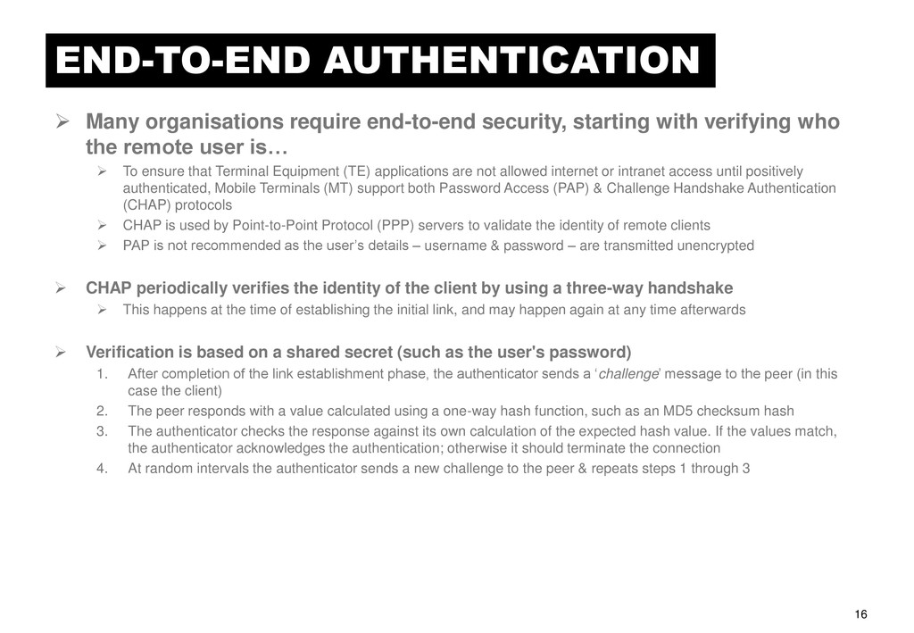
with verifying who the remote user is… To ensure that Terminal Equipment (TE) applications are not allowed internet or intranet access until positively authenticated, Mobile Terminals (MT) support both Password Access (PAP) & Challenge Handshake Authentication (CHAP) protocols CHAP is used by Point-to-Point Protocol (PPP) servers to validate the identity of remote clients PAP is not recommended as the user‟s details – username & password – are transmitted unencrypted CHAP periodically verifies the identity of the client by using a three-way handshake This happens at the time of establishing the initial link, and may happen again at any time afterwards Verification is based on a shared secret (such as the user's password) 1. After completion of the link establishment phase, the authenticator sends a „challenge‟ message to the peer (in this case the client) 2. The peer responds with a value calculated using a one-way hash function, such as an MD5 checksum hash 3. The authenticator checks the response against its own calculation of the expected hash value. If the values match, the authenticator acknowledges the authentication; otherwise it should terminate the connection 4. At random intervals the authenticator sends a new challenge to the peer & repeats steps 1 through 3
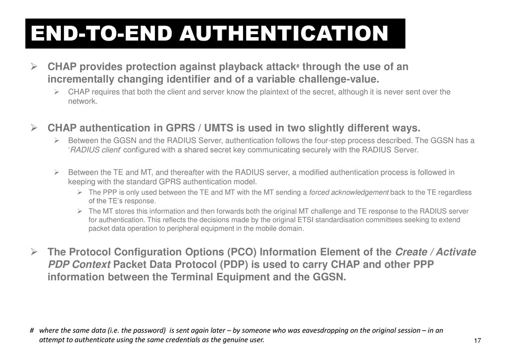
through the use of an incrementally changing identifier and of a variable challenge-value. CHAP requires that both the client and server know the plaintext of the secret, although it is never sent over the network. CHAP authentication in GPRS / UMTS is used in two slightly different ways. Between the GGSN and the RADIUS Server, authentication follows the four-step process described. The GGSN has a „RADIUS client‟ configured with a shared secret key communicating securely with the RADIUS Server. Between the TE and MT, and thereafter with the RADIUS server, a modified authentication process is followed in keeping with the standard GPRS authentication model. The PPP is only used between the TE and MT with the MT sending a forced acknowledgement back to the TE regardless of the TE‟s response. The MT stores this information and then forwards both the original MT challenge and TE response to the RADIUS server for authentication. This reflects the decisions made by the original ETSI standardisation committees seeking to extend packet data operation to peripheral equipment in the mobile domain. The Protocol Configuration Options (PCO) Information Element of the Create / Activate PDP Context Packet Data Protocol (PDP) is used to carry CHAP and other PPP information between the Terminal Equipment and the GGSN. # where the same data (i.e. the password) is sent again later – by someone who was eavesdropping on the original session – in an attempt to authenticate using the same credentials as the genuine user.
“MT Name” Username = “Alice” User Password = “LookingGlass” Authentication = “CHAP” CHAP-Challenge Authentication = “CHAP” Secret Key = “packetdata” Device Name = “MT Name” ID + User Password + Random Number MD5 Hash Response MD5 Algorithm ID = 01 Hash Response = ee090487b82c1e1323f” Name = “Alice” CHAP-Response A TE MT MT stores the authentication parameters for onward tranmission ID = 01 Name = “MT Name” CHAP-Success MT forces a positive acknowledgement CHAP-Success message CHAP (IN DETAIL)
PDP Type NSAPI QoS Requirements Hash Response = ee090487b82c1e1323f” Name = “Alice” “CHAP” Random Number = “87abfa444519b38af” ID = 01 Note: certain fields removed for clarity CHAP (IN DETAIL)
PDP Type TEID QoS Requirements Hash Response = ee090487b82c1e1323f” Name = “Alice” “CHAP” Random Number = “87abfa444519b38af” ID = 01 GGSN SGSN (& DNS) Note: additional fields removed for clarity CHAP (IN DETAIL)
MD5 Algorithm D GGSN (NAS) RADIUS Server RADIUS Access-Request Username = “Alice” Random Number = “87abfa444519b38af” ID = 01 NAS IP Address = “192.34.3.45” CHAP Password CHAP Challenge Hash Response = ee090487b82c1e1323f” Username = “Alice” User Password = “LookingGlass” Calculated = received Hash Response ? Note: additional fields removed for clarity Username used to lookup RADIUS server information CHAP (IN DETAIL)