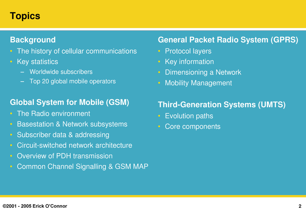
history of cellular communications • Key statistics – Worldwide subscribers – Top 20 global mobile operators Global System for Mobile (GSM) • The Radio environment • Basestation & Network subsystems • Subscriber data & addressing • Circuit-switched network architecture • Overview of PDH transmission • Common Channel Signalling & GSM MAP General Packet Radio System (GPRS) • Protocol layers • Key information • Dimensioning a Network • Mobility Management Third-Generation Systems (UMTS) • Evolution paths • Core components
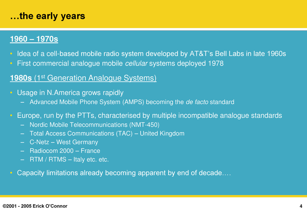
– 1970s • Idea of a cell-based mobile radio system developed by AT&T‟s Bell Labs in late 1960s • First commercial analogue mobile cellular systems deployed 1978 1980s (1st Generation Analogue Systems) • Usage in N.America grows rapidly – Advanced Mobile Phone System (AMPS) becoming the de facto standard • Europe, run by the PTTs, characterised by multiple incompatible analogue standards – Nordic Mobile Telecommunications (NMT-450) – Total Access Communications (TAC) – United Kingdom – C-Netz – West Germany – Radiocom 2000 – France – RTM / RTMS – Italy etc. etc. • Capacity limitations already becoming apparent by end of decade….
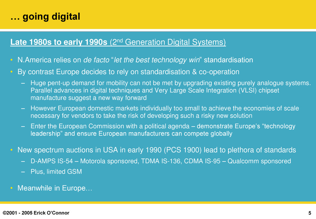
1980s to early 1990s (2nd Generation Digital Systems) • N.America relies on de facto “let the best technology win” standardisation • By contrast Europe decides to rely on standardisation & co-operation – Huge pent-up demand for mobility can not be met by upgrading existing purely analogue systems. Parallel advances in digital techniques and Very Large Scale Integration (VLSI) chipset manufacture suggest a new way forward – However European domestic markets individually too small to achieve the economies of scale necessary for vendors to take the risk of developing such a risky new solution – Enter the European Commission with a political agenda – demonstrate Europe‟s “technology leadership” and ensure European manufacturers can compete globally • New spectrum auctions in USA in early 1990 (PCS 1900) lead to plethora of standards – D-AMPS IS-54 – Motorola sponsored, TDMA IS-136, CDMA IS-95 – Qualcomm sponsored – Plus, limited GSM • Meanwhile in Europe…
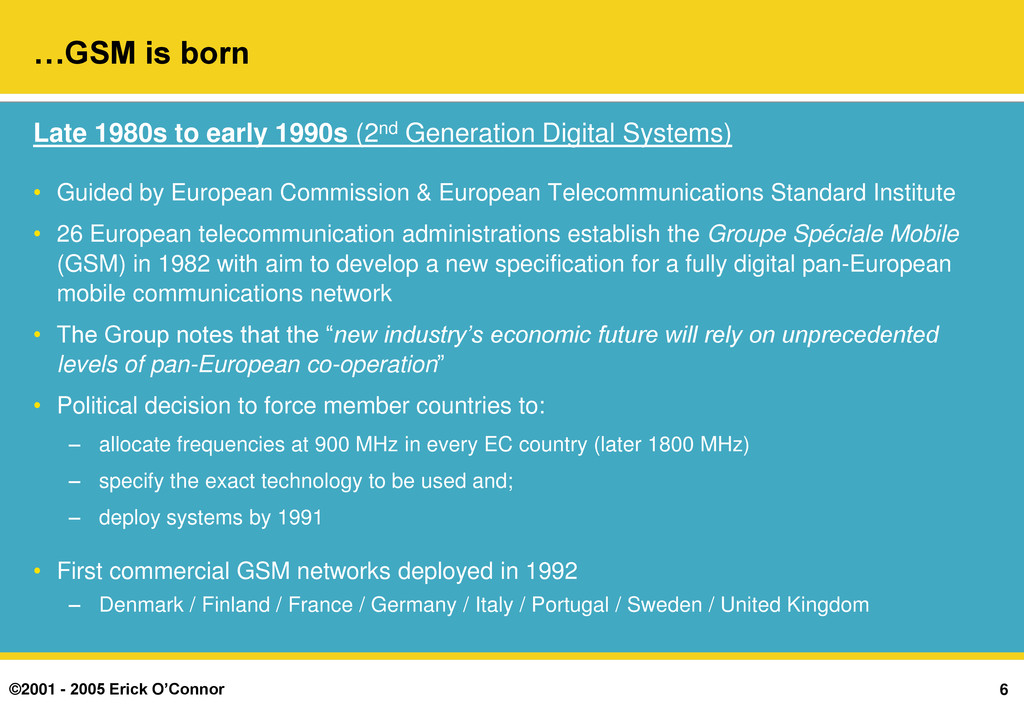
1980s to early 1990s (2nd Generation Digital Systems) • Guided by European Commission & European Telecommunications Standard Institute • 26 European telecommunication administrations establish the Groupe Spéciale Mobile (GSM) in 1982 with aim to develop a new specification for a fully digital pan-European mobile communications network • The Group notes that the “new industry’s economic future will rely on unprecedented levels of pan-European co-operation” • Political decision to force member countries to: – allocate frequencies at 900 MHz in every EC country (later 1800 MHz) – specify the exact technology to be used and; – deploy systems by 1991 • First commercial GSM networks deployed in 1992 – Denmark / Finland / France / Germany / Italy / Portugal / Sweden / United Kingdom
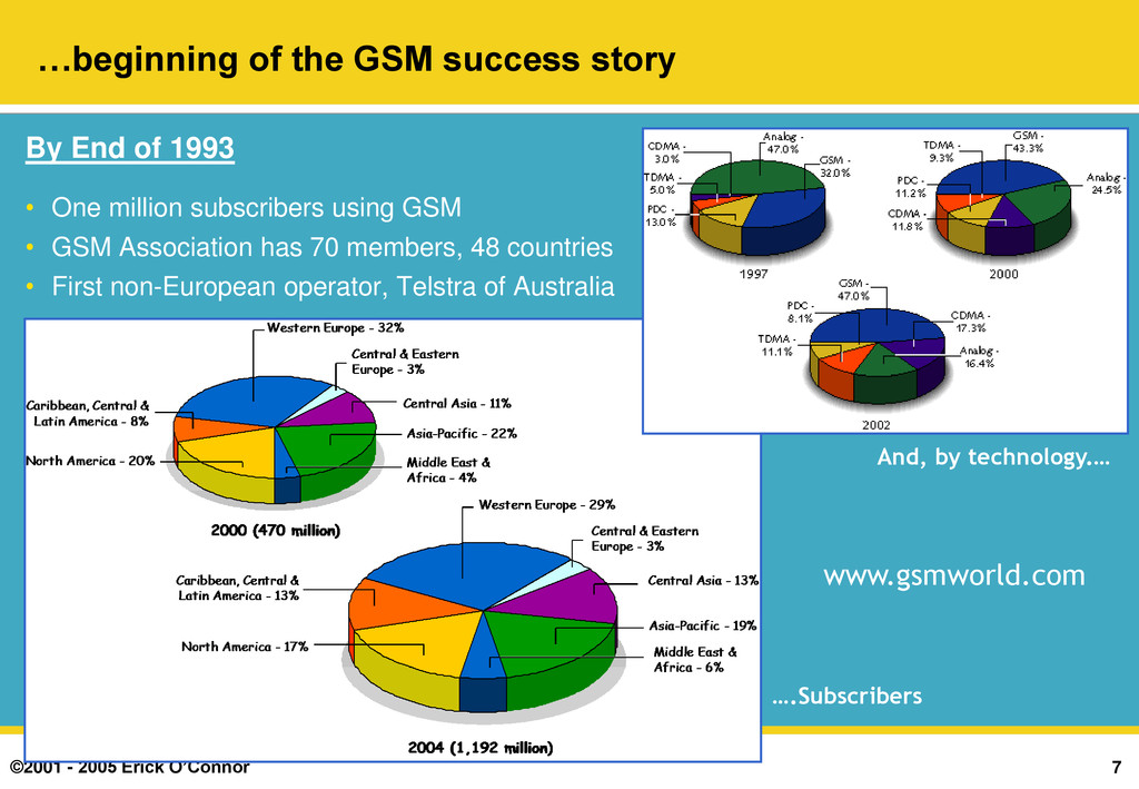
success story By End of 1993 • One million subscribers using GSM • GSM Association has 70 members, 48 countries • First non-European operator, Telstra of Australia ….Subscribers And, by technology.… www.gsmworld.com
century & 3rd generation services • Multiple operators per country & worldwide (800+) – intense price based competition – Huge growth in subscribers thanks to pre-paid but falling ARPU & high churn (c.25%) – Market close to saturation – slowing subscriber penetration growth rates (c.85%) • The challenge – what to do in future? • Europe keen to replicate commercial success of GSM but, Americans & Japanese had different views and needs – Japan had run out of spectrum for voice – Americans unhappy at being “dictated to” by a European standard – European vision of always on data & rich value added content services • America & Japan jointly force Europe to open up standardisation process so as not to once again “lock-out” other trading blocs‟ vendors – Creation of 3rd Gen Partnership Programme (3GPP) body – Heated standardisation on Wideband CDMA (Qualcomm vs Ericsson) – Final agreement on Universal Mobile Telecommunications Standard (UMTS) in 1998….
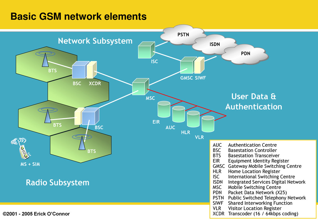
BTS MS + SIM XCDR Radio subsystem (i) • Basestation Transceiver (BTS) provides radio channels for signalling & user data • A BTS has 1 to 6 RF carriers per sector and 1(omni) to 6 sectors – e.g. 3/3/3 = 3 sector with 3 carriers per sector – 3 x 7 Timeslots x 3 = 63 Timeslots total – c.52 Erlangs @ 2% Grade of Service – c.2,000 users per BTS @ 25 mErl / User (90 seconds) • Frequency reuse depends on terrain, frequencies available etc. • Paired spectrum shared by Operators – 900 / 1800 MHz in Europe / Asia (25 & 75 MHz) – 1900 MHz in N.America • 200 kHz channel separation • 125 Channels @ 900 MHz 1 5 4 3 2 7 6 K=7 f1 f5 f4 f3 f2 f7 f6 1 5 4 3 2 7 6 1 3 2 f1 f3 f2 1 3 2 K=3 Frequency reuse & cluster formation
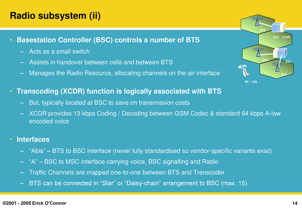
Basestation Controller (BSC) controls a number of BTS – Acts as a small switch – Assists in handover between cells and between BTS – Manages the Radio Resource, allocating channels on the air interface • Transcoding (XCDR) function is logically associated with BTS – But, typically located at BSC to save on transmission costs – XCDR provides 13 kbps Coding / Decoding between GSM Codec & standard 64 kbps A-law encoded voice • Interfaces – “Abis” – BTS to BSC interface (never fully standardised so vendor-specific variants exist) – “A” – BSC to MSC interface carrying voice, BSC signalling and Radio – Traffic Channels are mapped one-to-one between BTS and Transcoder – BTS can be connected in “Star” or “Daisy-chain” arrangement to BSC (max. 15) BTS BSC BSC BTS BTS MS + SIM XCDR
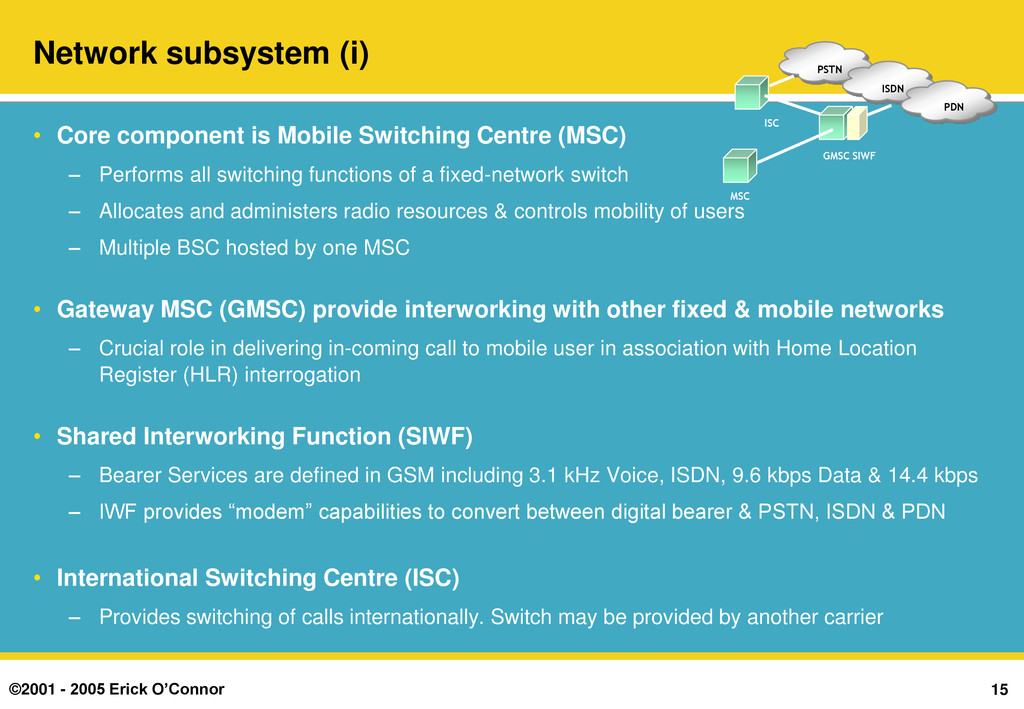
Core component is Mobile Switching Centre (MSC) – Performs all switching functions of a fixed-network switch – Allocates and administers radio resources & controls mobility of users – Multiple BSC hosted by one MSC • Gateway MSC (GMSC) provide interworking with other fixed & mobile networks – Crucial role in delivering in-coming call to mobile user in association with Home Location Register (HLR) interrogation • Shared Interworking Function (SIWF) – Bearer Services are defined in GSM including 3.1 kHz Voice, ISDN, 9.6 kbps Data & 14.4 kbps – IWF provides “modem” capabilities to convert between digital bearer & PSTN, ISDN & PDN • International Switching Centre (ISC) – Provides switching of calls internationally. Switch may be provided by another carrier GMSC ISC PSTN ISDN PDN MSC SIWF
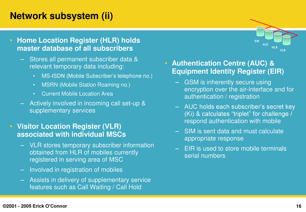
Home Location Register (HLR) holds master database of all subscribers – Stores all permanent subscriber data & relevant temporary data including: • MS-ISDN (Mobile Subscriber‟s telephone no.) • MSRN (Mobile Station Roaming no.) • Current Mobile Location Area – Actively involved in incoming call set-up & supplementary services • Visitor Location Register (VLR) associated with individual MSCs – VLR stores temporary subscriber information obtained from HLR of mobiles currently registered in serving area of MSC – Involved in registration of mobiles – Assists in delivery of supplementary service features such as Call Waiting / Call Hold • Authentication Centre (AUC) & Equipment Identity Register (EIR) – GSM is inherently secure using encryption over the air-interface and for authentication / registration – AUC holds each subscriber‟s secret key (Ki) & calculates “triplet” for challenge / respond authentication with mobile – SIM is sent data and must calculate appropriate response – EIR is used to store mobile terminals serial numbers VLR EIR AUC HLR
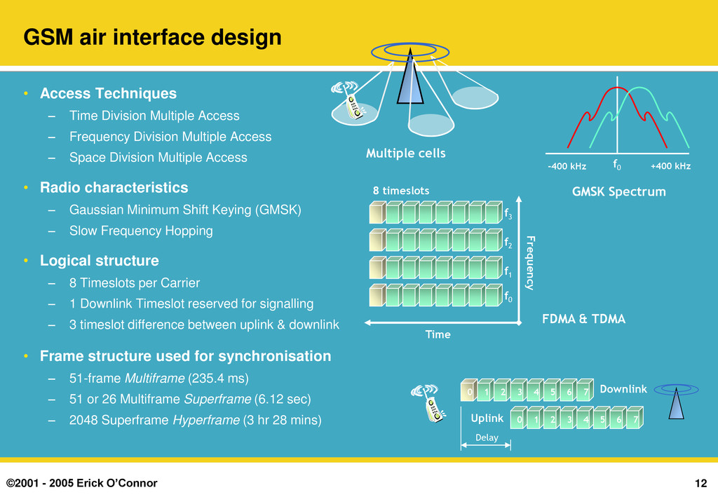
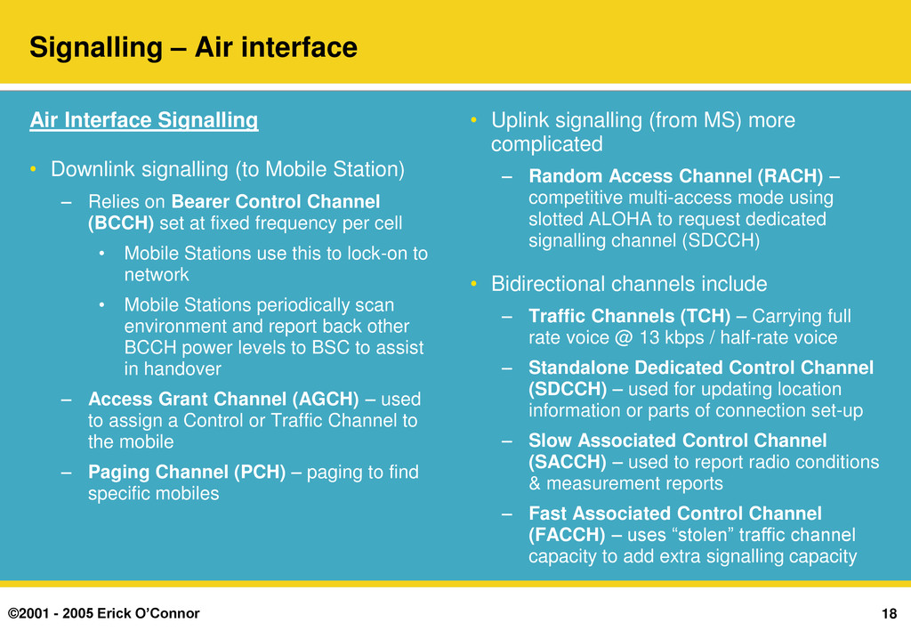
Air Interface Signalling • Downlink signalling (to Mobile Station) – Relies on Bearer Control Channel (BCCH) set at fixed frequency per cell • Mobile Stations use this to lock-on to network • Mobile Stations periodically scan environment and report back other BCCH power levels to BSC to assist in handover – Access Grant Channel (AGCH) – used to assign a Control or Traffic Channel to the mobile – Paging Channel (PCH) – paging to find specific mobiles • Uplink signalling (from MS) more complicated – Random Access Channel (RACH) – competitive multi-access mode using slotted ALOHA to request dedicated signalling channel (SDCCH) • Bidirectional channels include – Traffic Channels (TCH) – Carrying full rate voice @ 13 kbps / half-rate voice – Standalone Dedicated Control Channel (SDCCH) – used for updating location information or parts of connection set-up – Slow Associated Control Channel (SACCH) – used to report radio conditions & measurement reports – Fast Associated Control Channel (FACCH) – uses “stolen” traffic channel capacity to add extra signalling capacity
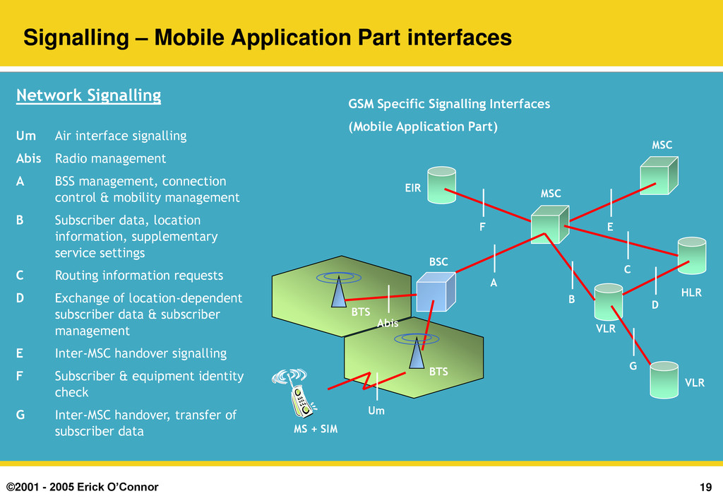
Part interfaces BTS BSC BTS MS + SIM VLR EIR HLR MSC MSC VLR A F E Abis C B G D Um GSM Specific Signalling Interfaces (Mobile Application Part) Network Signalling Um Air interface signalling Abis Radio management A BSS management, connection control & mobility management B Subscriber data, location information, supplementary service settings C Routing information requests D Exchange of location-dependent subscriber data & subscriber management E Inter-MSC handover signalling F Subscriber & equipment identity check G Inter-MSC handover, transfer of subscriber data
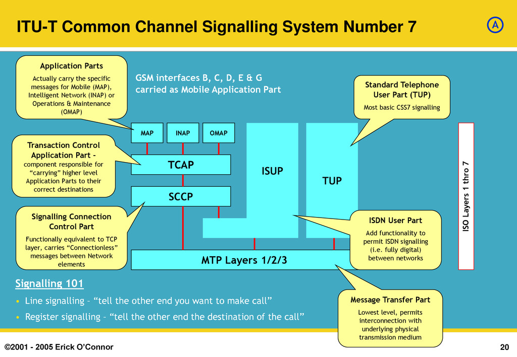
System Number 7 MTP Layers 1/2/3 TCAP SCCP MAP INAP OMAP ISUP TUP Standard Telephone User Part (TUP) Most basic CSS7 signalling ISDN User Part Add functionality to permit ISDN signalling (i.e. fully digital) between networks Message Transfer Part Lowest level, permits interconnection with underlying physical transmission medium Signalling Connection Control Part Functionally equivalent to TCP layer, carries “Connectionless” messages between Network elements Application Parts Actually carry the specific messages for Mobile (MAP), Intelligent Network (INAP) or Operations & Maintenance (OMAP) Transaction Control Application Part – component responsible for “carrying” higher level Application Parts to their correct destinations ISO Layers 1 thro 7 Signalling 101 • Line signalling – “tell the other end you want to make call” • Register signalling – “tell the other end the destination of the call” GSM interfaces B, C, D, E & G carried as Mobile Application Part A
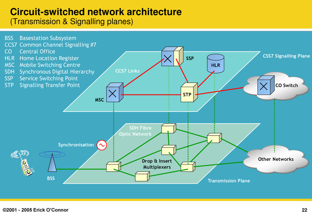
Transmission Plane Synchronisation Other Networks Drop & Insert Multiplexers BSS Circuit-switched network architecture (Transmission & Signalling planes) BSS Basestation Subsystem CCS7 Common Channel Signalling #7 CO Central Office HLR Home Location Register MSC Mobile Switching Centre SDH Synchronous Digital Hierarchy SSP Service Switching Point STP Signalling Transfer Point STP HLR CSS7 Signalling Plane MSC CCS7 Links SSP CO Switch
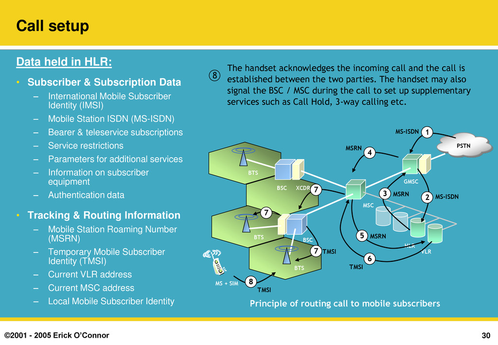
BTS MS + SIM XCDR GMSC PSTN MSC VLR HLR Principle of routing call to mobile subscribers 1 MS-ISDN Call is placed to a mobile subscriber by dialling the mobile number (MS-ISDN). 1 Call setup Data held in HLR: • Subscriber & Subscription Data – International Mobile Subscriber Identity (IMSI) – Mobile Station ISDN (MS-ISDN) – Bearer & teleservice subscriptions – Service restrictions – Parameters for additional services – Information on subscriber equipment – Authentication data • Tracking & Routing Information – Mobile Station Roaming Number (MSRN) – Temporary Mobile Subscriber Identity (TMSI) – Current VLR address – Current MSC address – Local Mobile Subscriber Identity
the MSC interrogates the HLR to find status and location of mobile subscriber. BTS BSC BSC BTS BTS MS + SIM XCDR GMSC PSTN MSC VLR HLR Principle of routing call to mobile subscribers 1 MS-ISDN 2 MS-ISDN Call setup Data held in HLR: • Subscriber & Subscription Data – International Mobile Subscriber Identity (IMSI) – Mobile Station ISDN (MS-ISDN) – Bearer & teleservice subscriptions – Service restrictions – Parameters for additional services – Information on subscriber equipment – Authentication data • Tracking & Routing Information – Mobile Station Roaming Number (MSRN) – Temporary Mobile Subscriber Identity (TMSI) – Current VLR address – Current MSC address – Local Mobile Subscriber Identity
the MSRN – a “virtual” number telling the GMSC how to route the call to the serving MSC. BTS BSC BSC BTS BTS MS + SIM XCDR GMSC PSTN MSC VLR HLR Principle of routing call to mobile subscribers 1 MS-ISDN 2 MS-ISDN 3 MSRN Call setup Data held in HLR: • Subscriber & Subscription Data – International Mobile Subscriber Identity (IMSI) – Mobile Station ISDN (MS-ISDN) – Bearer & teleservice subscriptions – Service restrictions – Parameters for additional services – Information on subscriber equipment – Authentication data • Tracking & Routing Information – Mobile Station Roaming Number (MSRN) – Temporary Mobile Subscriber Identity (TMSI) – Current VLR address – Current MSC address – Local Mobile Subscriber Identity
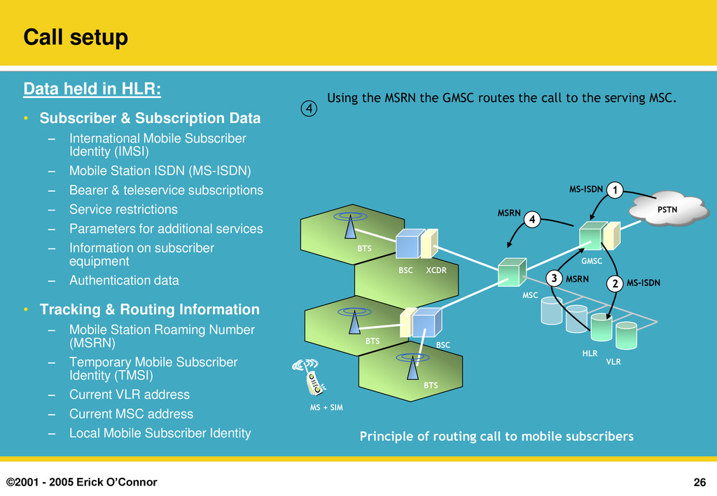
the GMSC routes the call to the serving MSC. BTS BSC BSC BTS BTS MS + SIM XCDR GMSC PSTN MSC VLR HLR Principle of routing call to mobile subscribers 1 MS-ISDN 2 MS-ISDN 3 MSRN 4 MSRN Call setup Data held in HLR: • Subscriber & Subscription Data – International Mobile Subscriber Identity (IMSI) – Mobile Station ISDN (MS-ISDN) – Bearer & teleservice subscriptions – Service restrictions – Parameters for additional services – Information on subscriber equipment – Authentication data • Tracking & Routing Information – Mobile Station Roaming Number (MSRN) – Temporary Mobile Subscriber Identity (TMSI) – Current VLR address – Current MSC address – Local Mobile Subscriber Identity
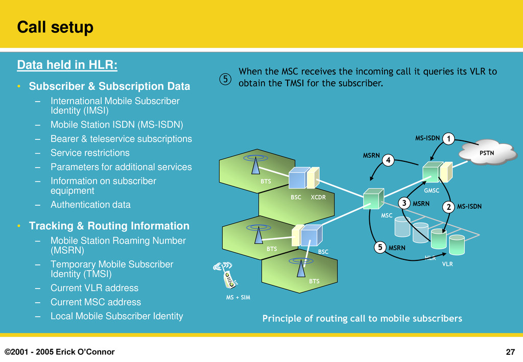
MSC interrogates the HLR to find status and location of mobile subscriber. 5 When the MSC receives the incoming call it queries its VLR to obtain the TMSI for the subscriber. BTS BSC BSC BTS BTS MS + SIM XCDR GMSC PSTN MSC VLR HLR Principle of routing call to mobile subscribers 1 MS-ISDN 2 MS-ISDN 3 MSRN 4 MSRN 5 MSRN Call setup Data held in HLR: • Subscriber & Subscription Data – International Mobile Subscriber Identity (IMSI) – Mobile Station ISDN (MS-ISDN) – Bearer & teleservice subscriptions – Service restrictions – Parameters for additional services – Information on subscriber equipment – Authentication data • Tracking & Routing Information – Mobile Station Roaming Number (MSRN) – Temporary Mobile Subscriber Identity (TMSI) – Current VLR address – Current MSC address – Local Mobile Subscriber Identity
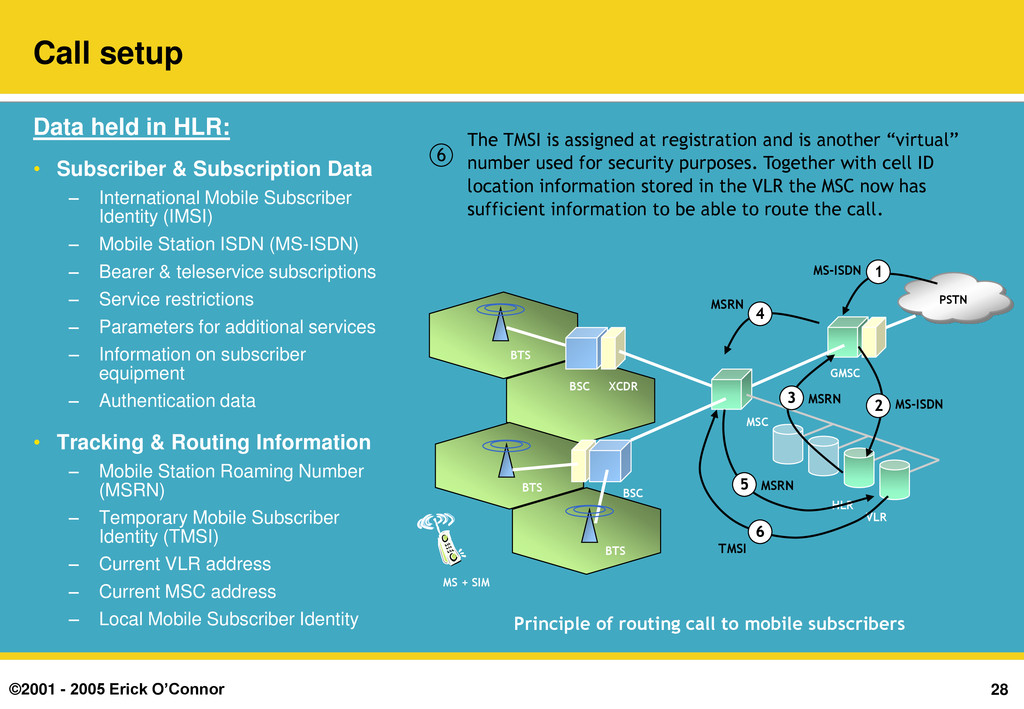
at registration and is another “virtual” number used for security purposes. Together with cell ID location information stored in the VLR the MSC now has sufficient information to be able to route the call. 6 BTS BSC BSC BTS BTS MS + SIM XCDR GMSC PSTN MSC VLR HLR Principle of routing call to mobile subscribers 1 MS-ISDN 2 MS-ISDN 3 MSRN 4 MSRN 5 MSRN 6 TMSI Call setup Data held in HLR: • Subscriber & Subscription Data – International Mobile Subscriber Identity (IMSI) – Mobile Station ISDN (MS-ISDN) – Bearer & teleservice subscriptions – Service restrictions – Parameters for additional services – Information on subscriber equipment – Authentication data • Tracking & Routing Information – Mobile Station Roaming Number (MSRN) – Temporary Mobile Subscriber Identity (TMSI) – Current VLR address – Current MSC address – Local Mobile Subscriber Identity
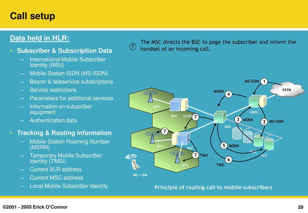
BSC to page the subscriber and inform the handset of an incoming call. 7 BTS BSC BSC BTS BTS MS + SIM XCDR GMSC PSTN MSC VLR HLR Principle of routing call to mobile subscribers 1 MS-ISDN 2 MS-ISDN 3 MSRN 4 MSRN 5 MSRN 6 TMSI 7 7 7 TMSI Call setup Data held in HLR: • Subscriber & Subscription Data – International Mobile Subscriber Identity (IMSI) – Mobile Station ISDN (MS-ISDN) – Bearer & teleservice subscriptions – Service restrictions – Parameters for additional services – Information on subscriber equipment – Authentication data • Tracking & Routing Information – Mobile Station Roaming Number (MSRN) – Temporary Mobile Subscriber Identity (TMSI) – Current VLR address – Current MSC address – Local Mobile Subscriber Identity
incoming call and the call is established between the two parties. The handset may also signal the BSC / MSC during the call to set up supplementary services such as Call Hold, 3-way calling etc. 8 BTS BSC BSC BTS BTS MS + SIM XCDR GMSC PSTN MSC VLR HLR Principle of routing call to mobile subscribers 1 MS-ISDN 2 MS-ISDN 3 MSRN 4 MSRN 5 MSRN 6 TMSI 7 7 7 TMSI 8 TMSI Call setup Data held in HLR: • Subscriber & Subscription Data – International Mobile Subscriber Identity (IMSI) – Mobile Station ISDN (MS-ISDN) – Bearer & teleservice subscriptions – Service restrictions – Parameters for additional services – Information on subscriber equipment – Authentication data • Tracking & Routing Information – Mobile Station Roaming Number (MSRN) – Temporary Mobile Subscriber Identity (TMSI) – Current VLR address – Current MSC address – Local Mobile Subscriber Identity
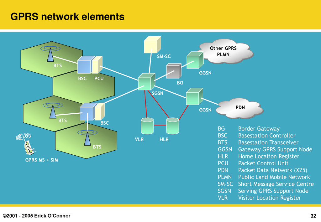
Border Gateway BSC Basestation Controller BTS Basestation Transceiver GGSN Gateway GPRS Support Node HLR Home Location Register PCU Packet Control Unit PDN Packet Data Network (X25) PLMN Public Land Mobile Network SM-SC Short Message Service Centre SGSN Serving GPRS Support Node VLR Visitor Location Register HLR VLR BTS BSC BSC BTS BTS GPRS MS + SIM PCU Other GPRS PLMN GGSN SGSN PDN GGSN SM-SC BG
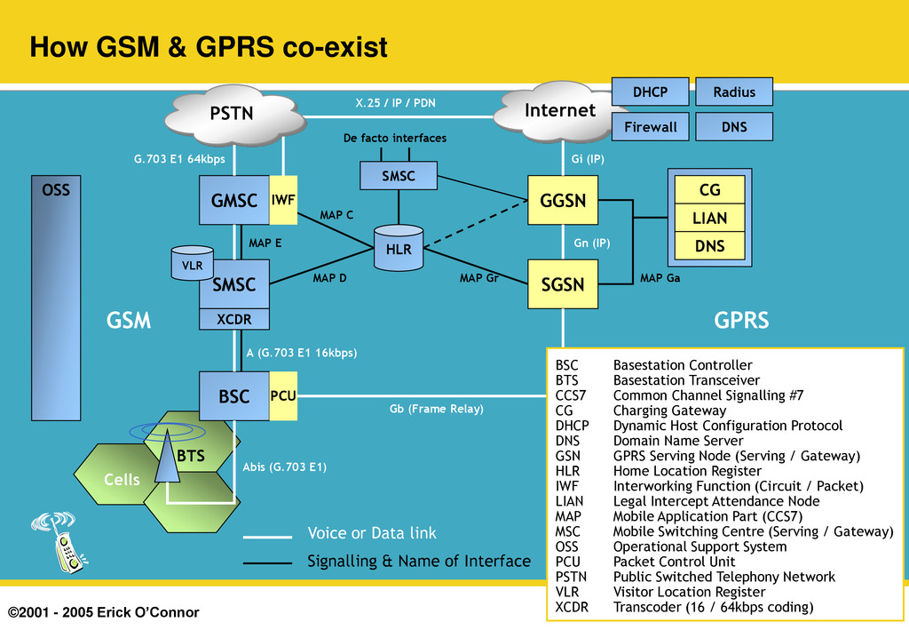
& GPRS co-exist OSS CG LIAN DNS Abis (G.703 E1) BSC SMSC VLR XCDR A (G.703 E1 16kbps) GGSN Gn (IP) MAP Gr MAP Ga GMSC MAP E Signalling & Name of Interface Voice or Data link HLR MAP D MAP C SMSC De facto interfaces IWF Internet X.25 / IP / PDN PSTN G.703 E1 64kbps DHCP Firewall DNS Radius Gi (IP) GSM PCU SGSN Gb (Frame Relay) GPRS BSC Basestation Controller BTS Basestation Transceiver CCS7 Common Channel Signalling #7 CG Charging Gateway DHCP Dynamic Host Configuration Protocol DNS Domain Name Server GSN GPRS Serving Node (Serving / Gateway) HLR Home Location Register IWF Interworking Function (Circuit / Packet) LIAN Legal Intercept Attendance Node MAP Mobile Application Part (CCS7) MSC Mobile Switching Centre (Serving / Gateway) OSS Operational Support System PCU Packet Control Unit PSTN Public Switched Telephony Network VLR Visitor Location Register XCDR Transcoder (16 / 64kbps coding)
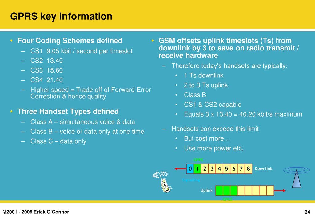
Four Coding Schemes defined – CS1 9.05 kbit / second per timeslot – CS2 13.40 – CS3 15.60 – CS4 21.40 – Higher speed = Trade off of Forward Error Correction & hence quality • Three Handset Types defined – Class A – simultaneous voice & data – Class B – voice or data only at one time – Class C – data only • GSM offsets uplink timeslots (Ts) from downlink by 3 to save on radio transmit / receive hardware – Therefore today‟s handsets are typically: • 1 Ts downlink • 2 to 3 Ts uplink • Class B • CS1 & CS2 capable • Equals 3 x 13.40 = 40.20 kbit/s maximum – Handsets can exceed this limit • But cost more… • Use more power etc, 1 2 3 4 5 6 7 8 GPRS GPRS 0 Signalling Downlink Uplink
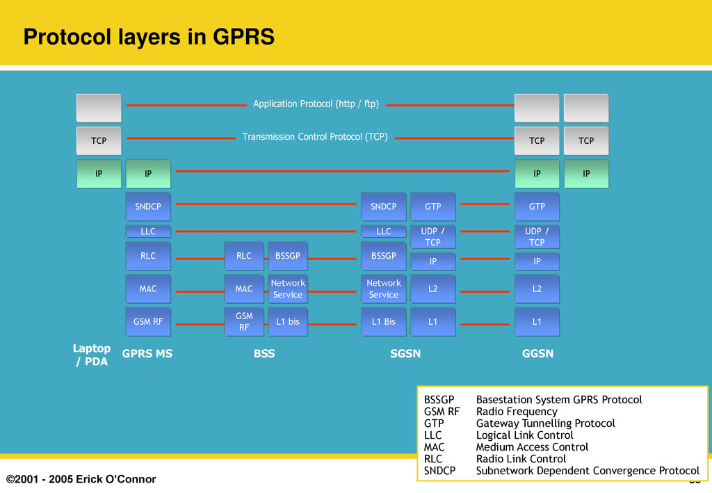
Laptop / PDA GPRS MS BSS SGSN GGSN Application Protocol (http / ftp) Transmission Control Protocol (TCP) GSM RF IP MAC RLC LLC SNDCP GSM RF MAC RLC L1 bis Network Service BSSGP L1 Bis Network Service BSSGP LLC SNDCP L1 L2 IP UDP / TCP GTP L1 L2 IP UDP / TCP GTP IP TCP IP TCP IP TCP BSSGP Basestation System GPRS Protocol GSM RF Radio Frequency GTP Gateway Tunnelling Protocol LLC Logical Link Control MAC Medium Access Control RLC Radio Link Control SNDCP Subnetwork Dependent Convergence Protocol
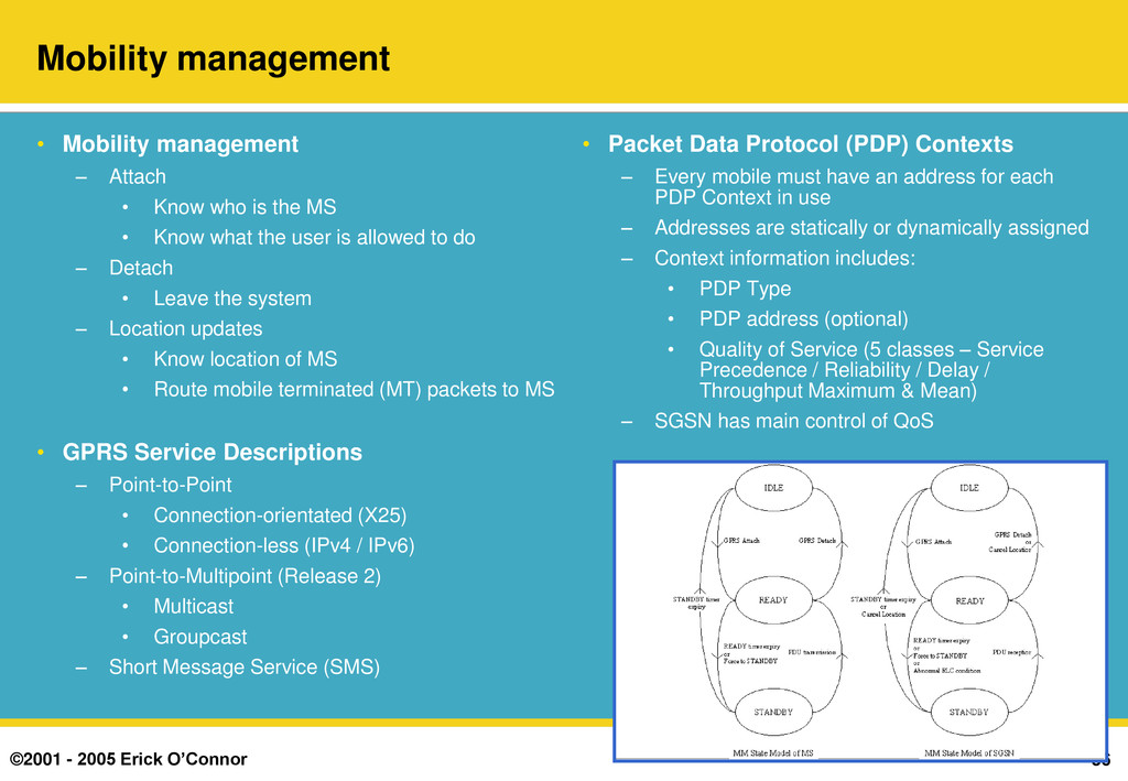
management – Attach • Know who is the MS • Know what the user is allowed to do – Detach • Leave the system – Location updates • Know location of MS • Route mobile terminated (MT) packets to MS • GPRS Service Descriptions – Point-to-Point • Connection-orientated (X25) • Connection-less (IPv4 / IPv6) – Point-to-Multipoint (Release 2) • Multicast • Groupcast – Short Message Service (SMS) • Packet Data Protocol (PDP) Contexts – Every mobile must have an address for each PDP Context in use – Addresses are statically or dynamically assigned – Context information includes: • PDP Type • PDP address (optional) • Quality of Service (5 classes – Service Precedence / Reliability / Delay / Throughput Maximum & Mean) – SGSN has main control of QoS
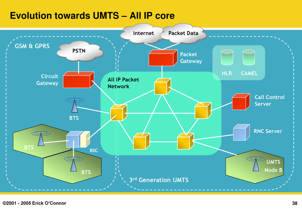
All IP core BTS BSC BTS UMTS Node B RNC Server All IP Packet Network Packet Gateway Circuit Gateway BTS Call Control Server PSTN CAMEL HLR GSM & GPRS 3rd Generation UMTS Internet Packet Data