Share
To Build Cloud Native Apps
Using Composable Enterprise Architecture
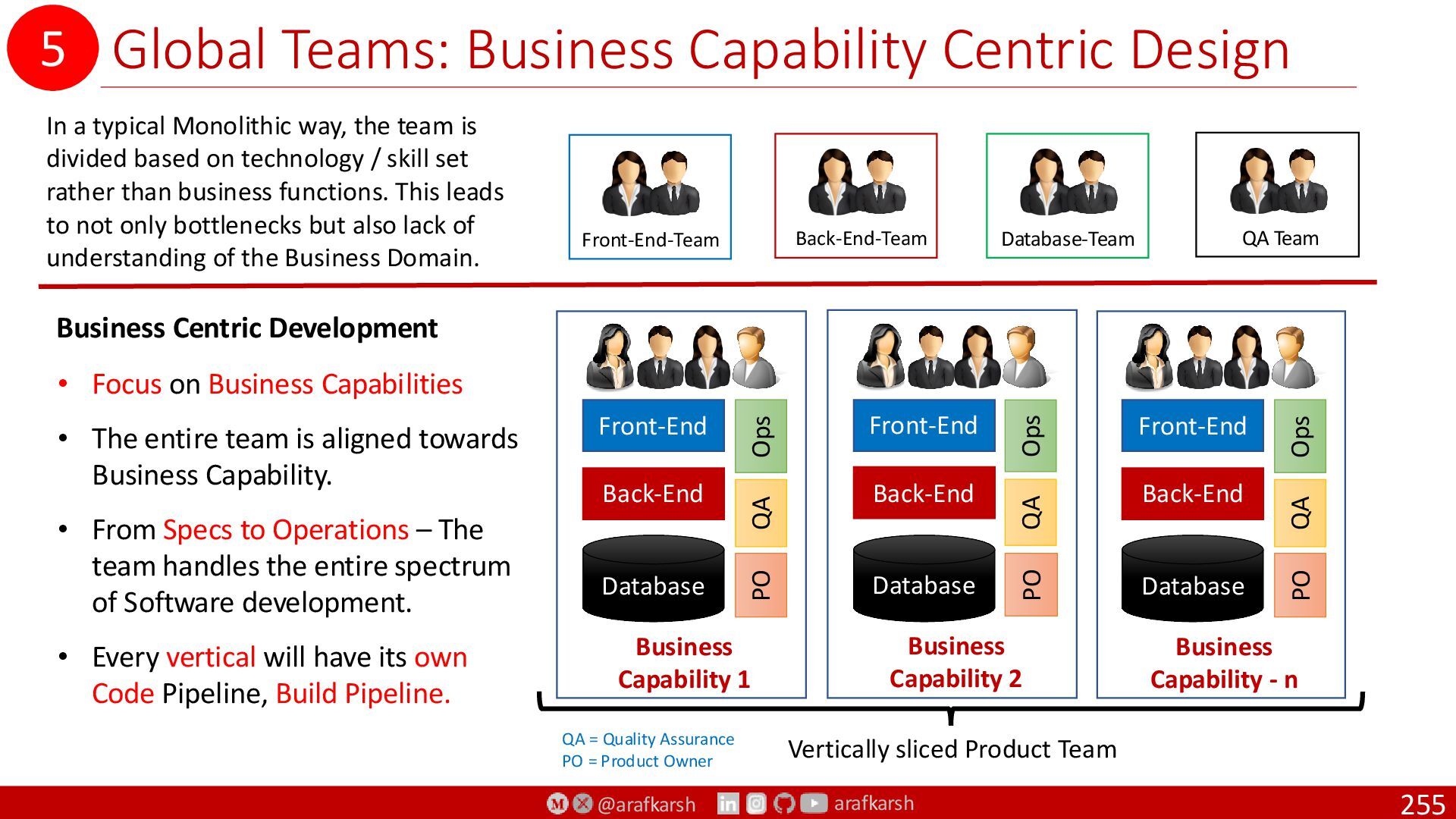
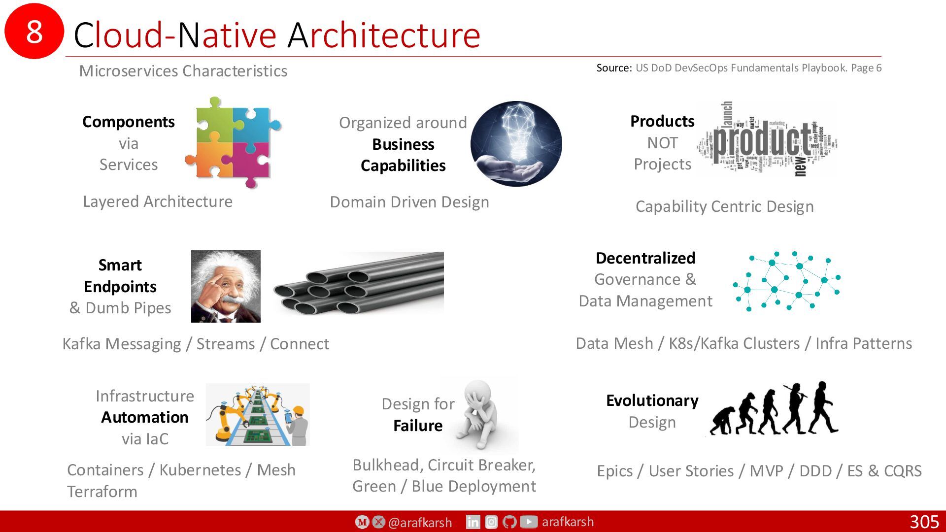
Capability Centric Design
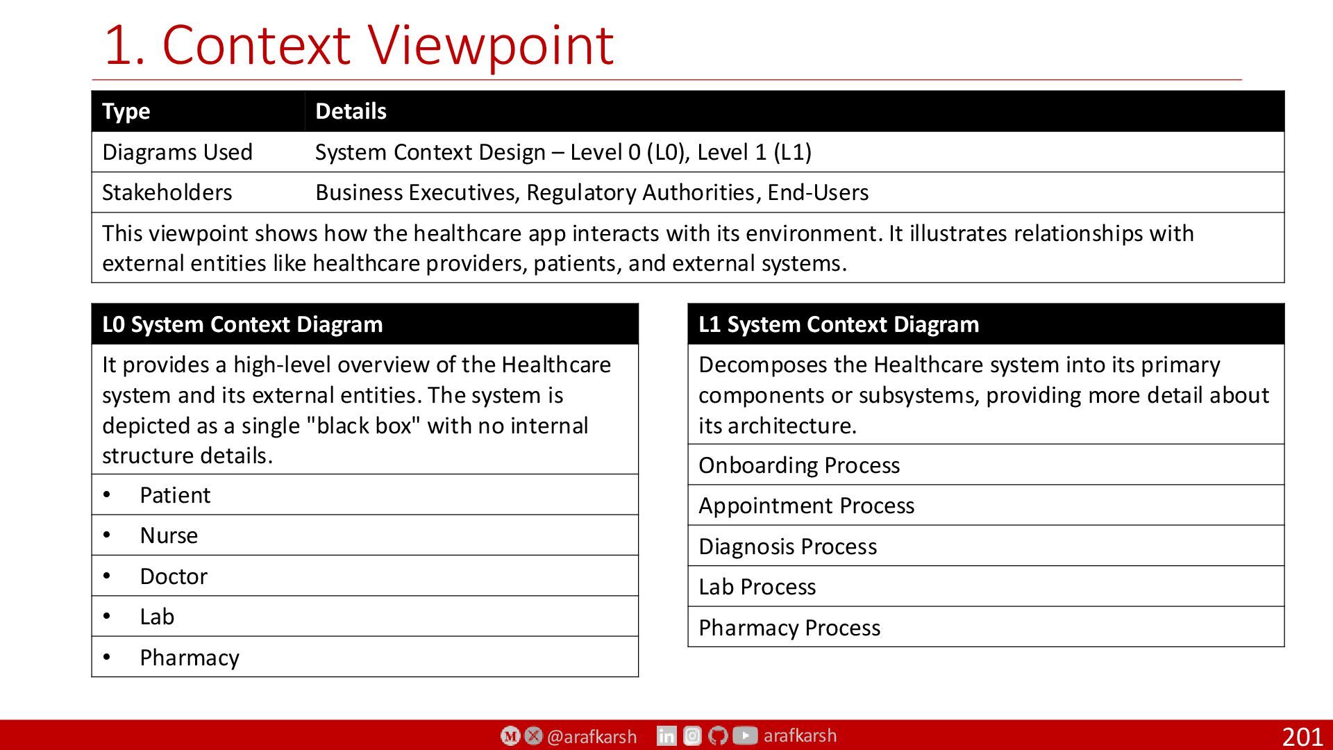
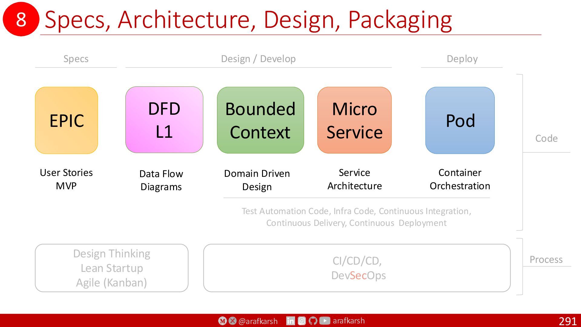
System Context Diagram (DFD L0)
Data Flow Diagrams L0, L1, L2
C4 Diagrams (Context to Code)
4+1 Model of Architecture
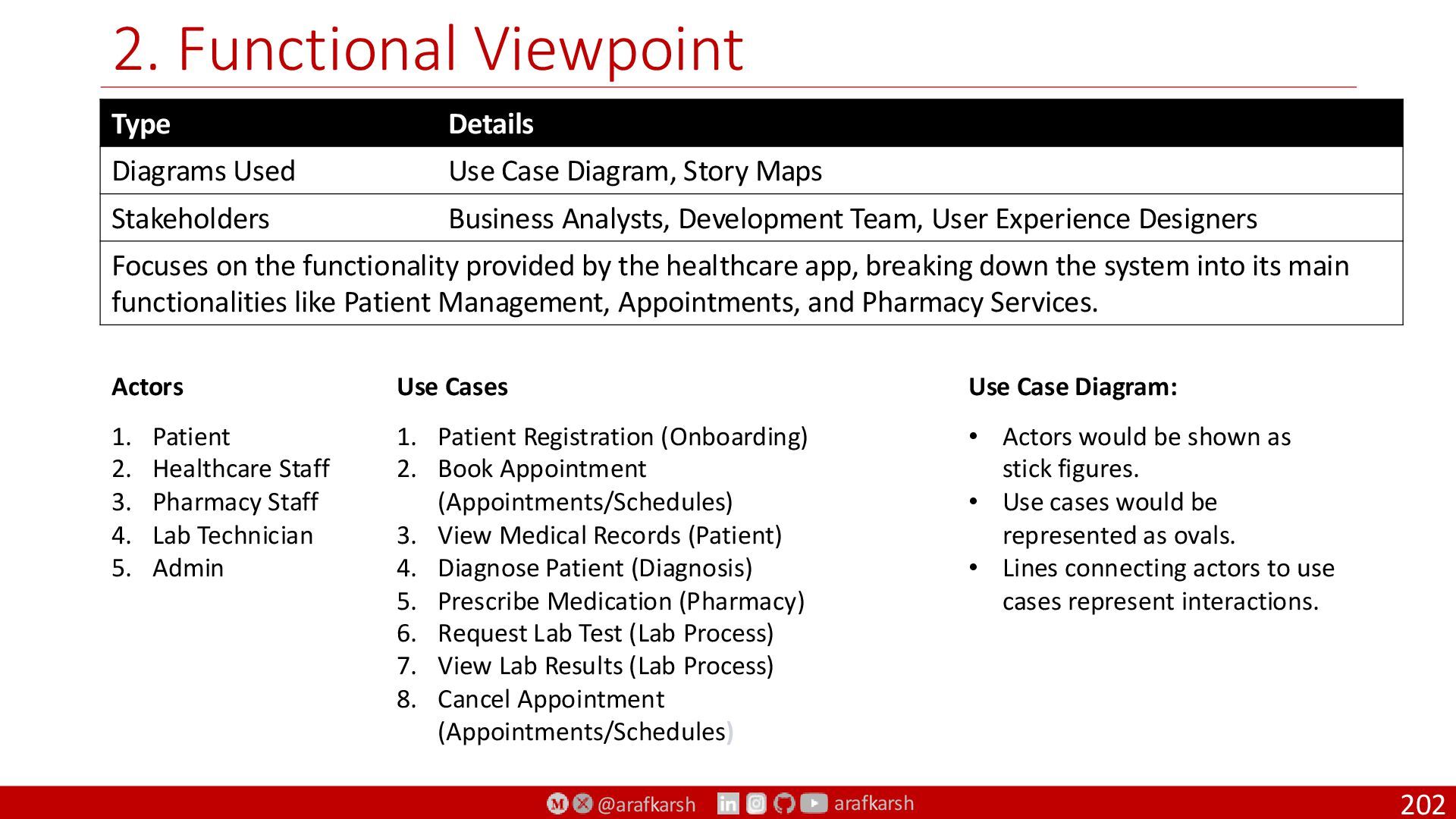
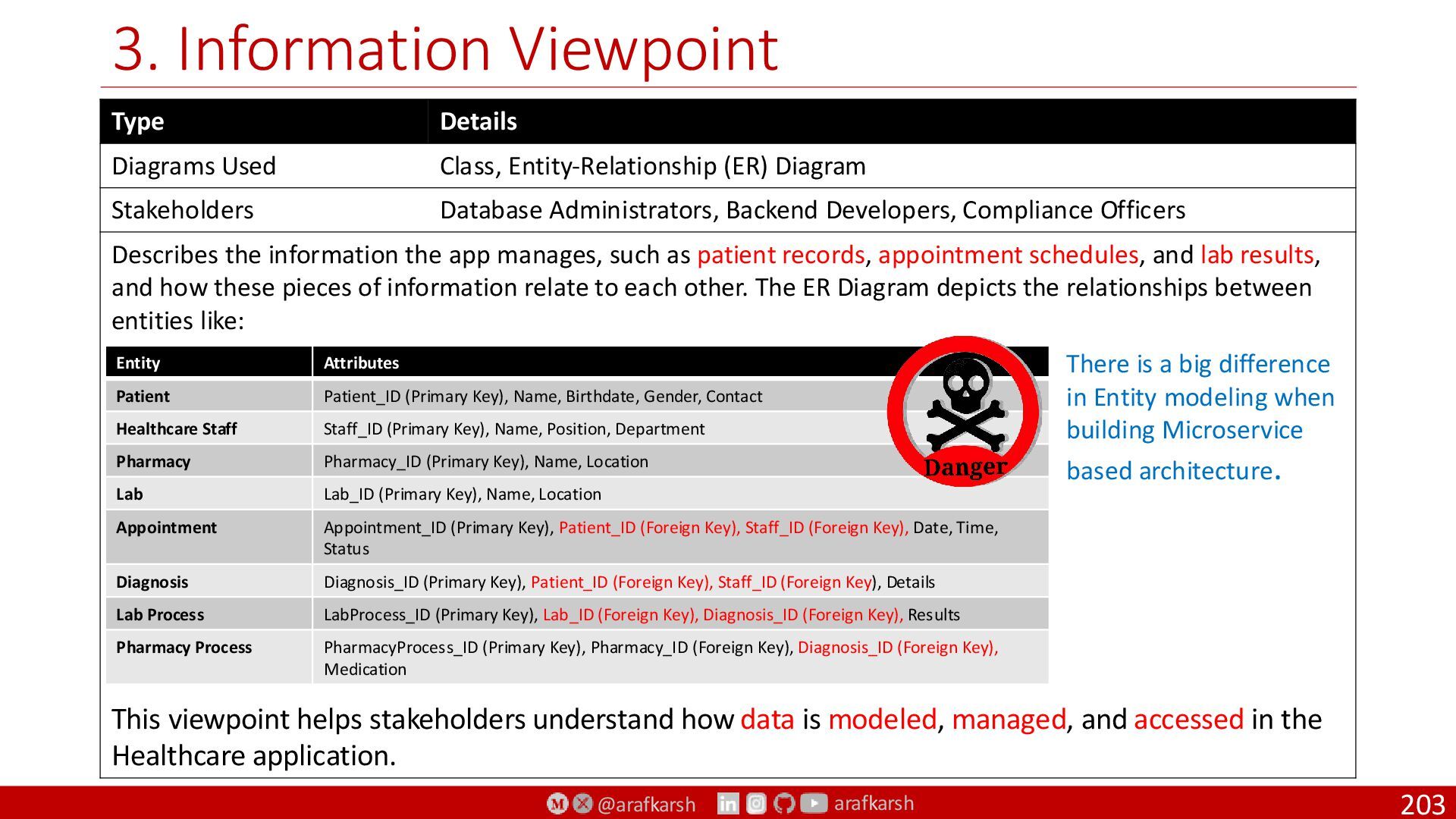
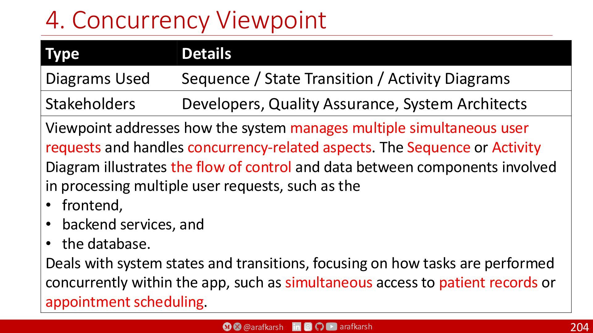
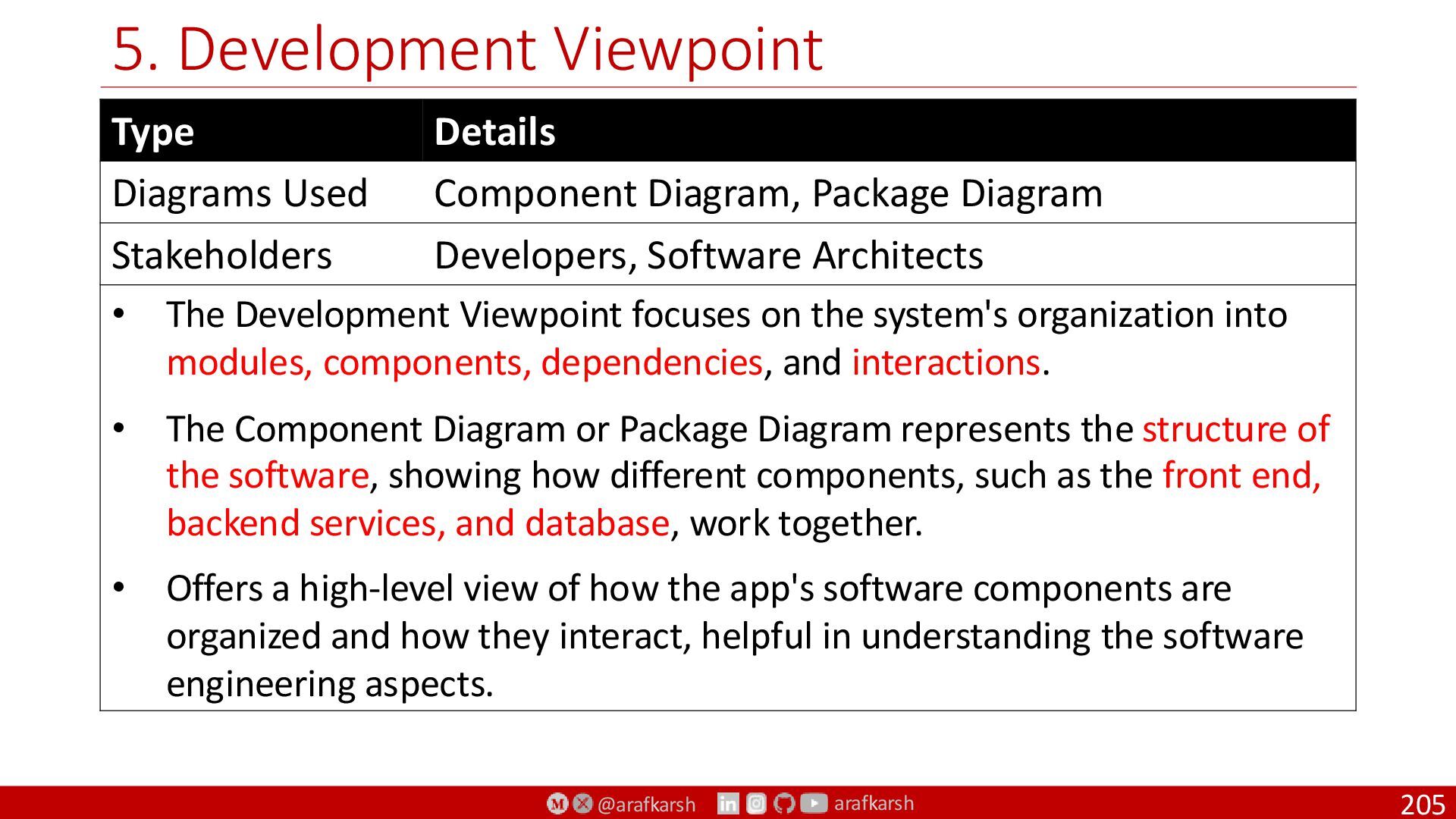
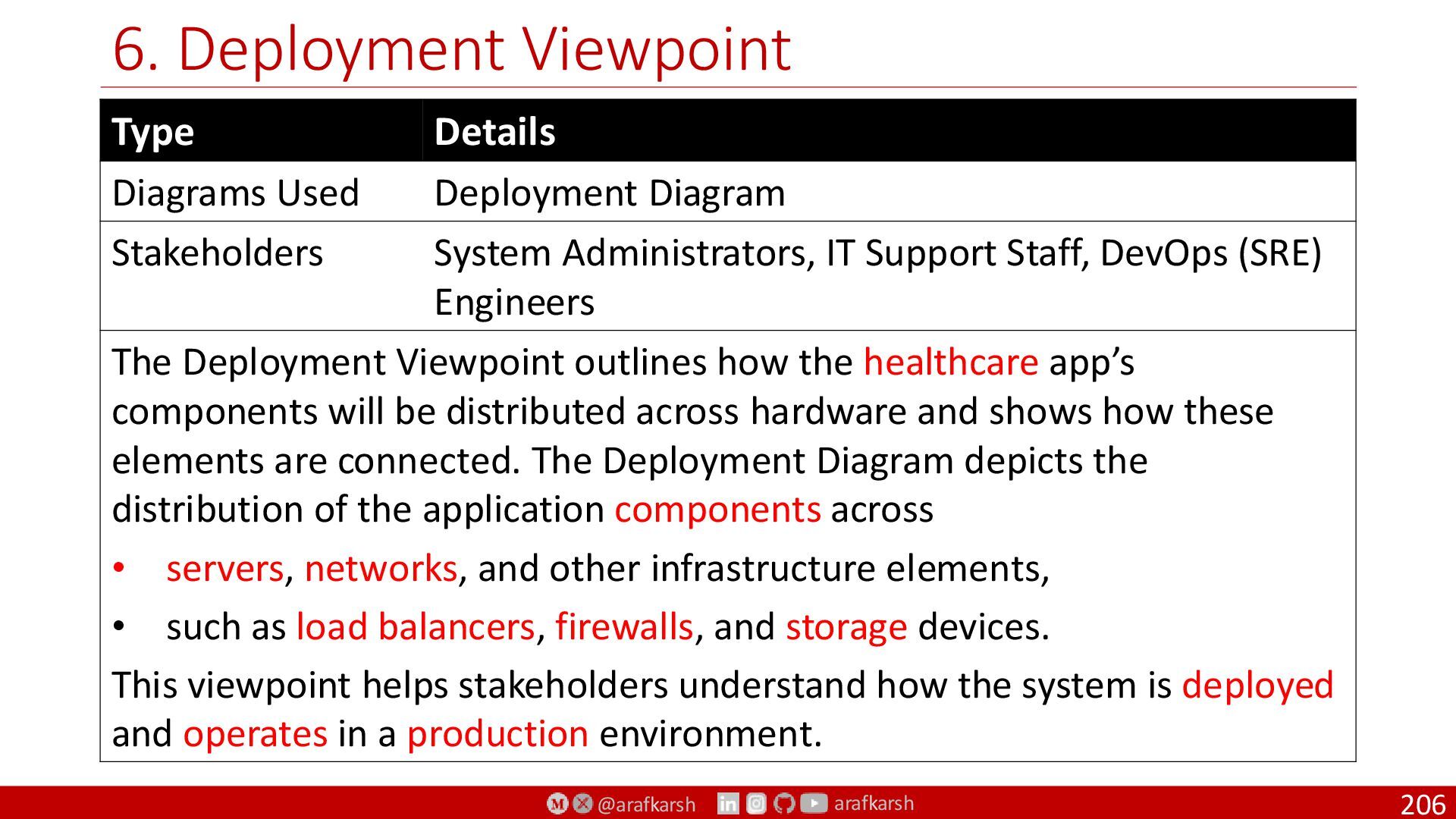
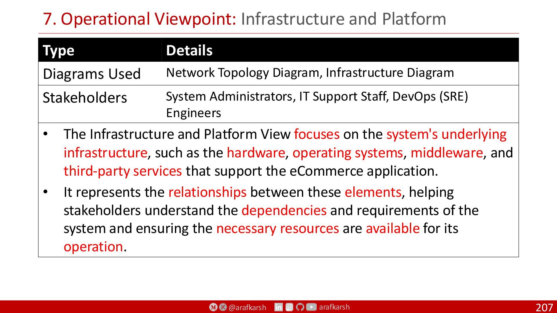
UML 2.5 Diagrams (Behaviour, Interaction & Structural)
Zachman Framework
ISO/IEC/IEEE 42010:2011 / 42010:2022
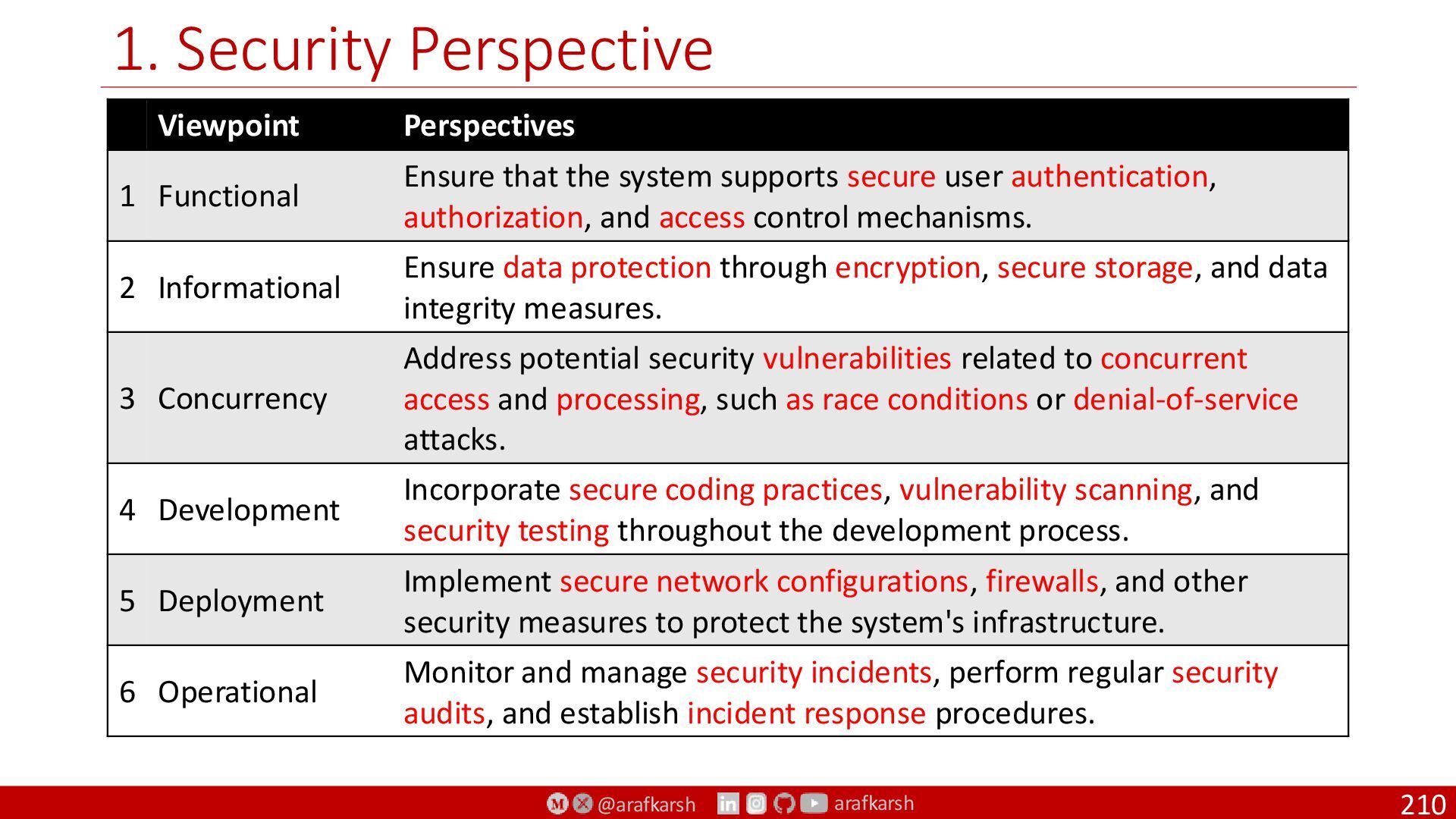
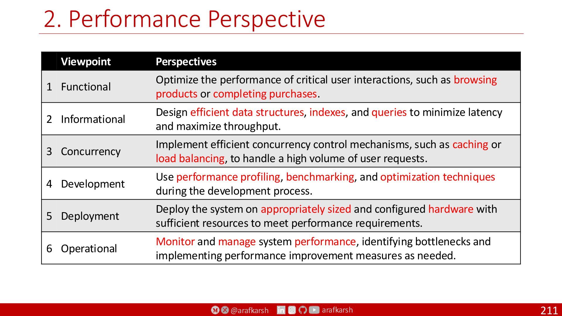
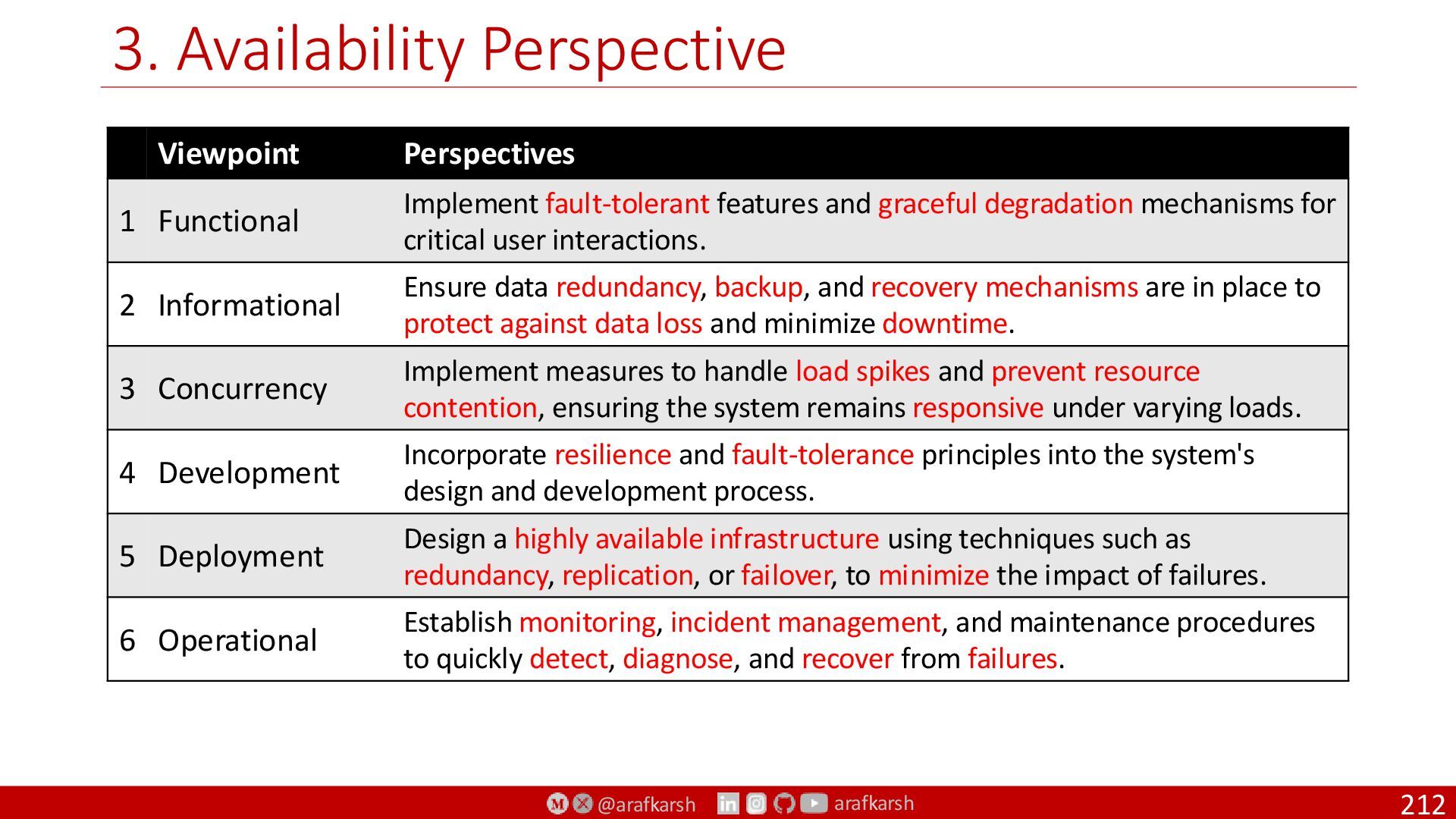
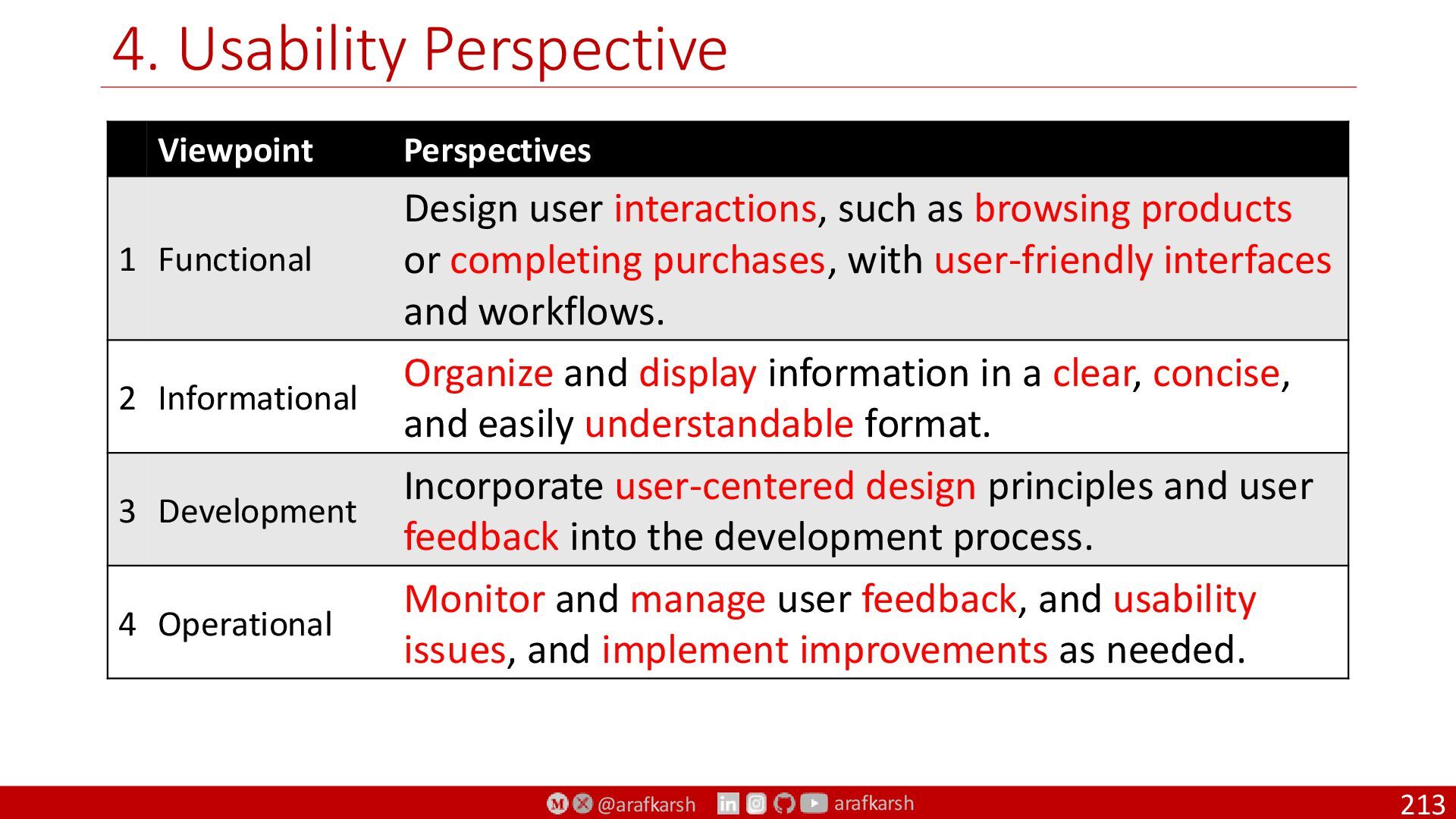
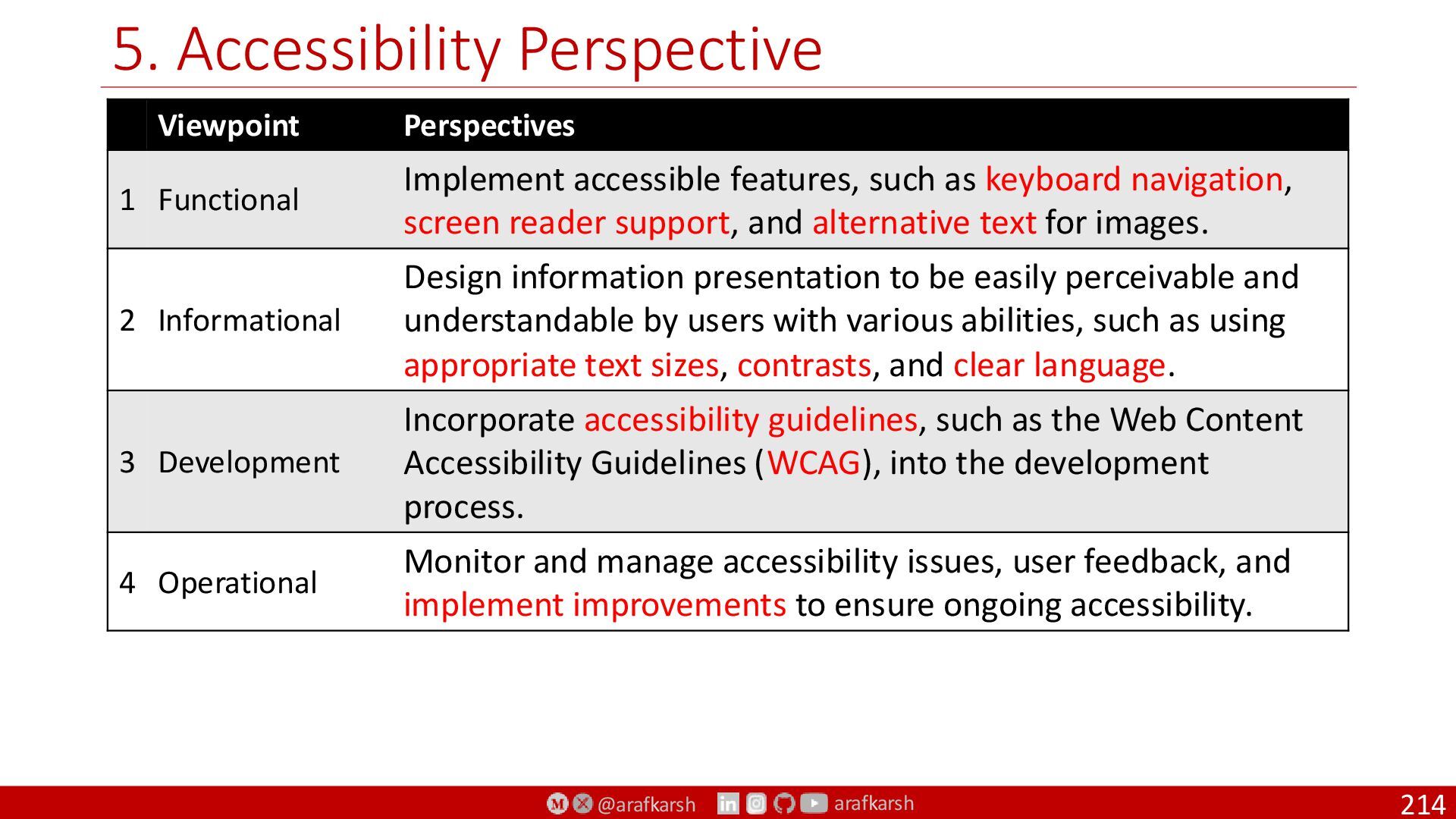
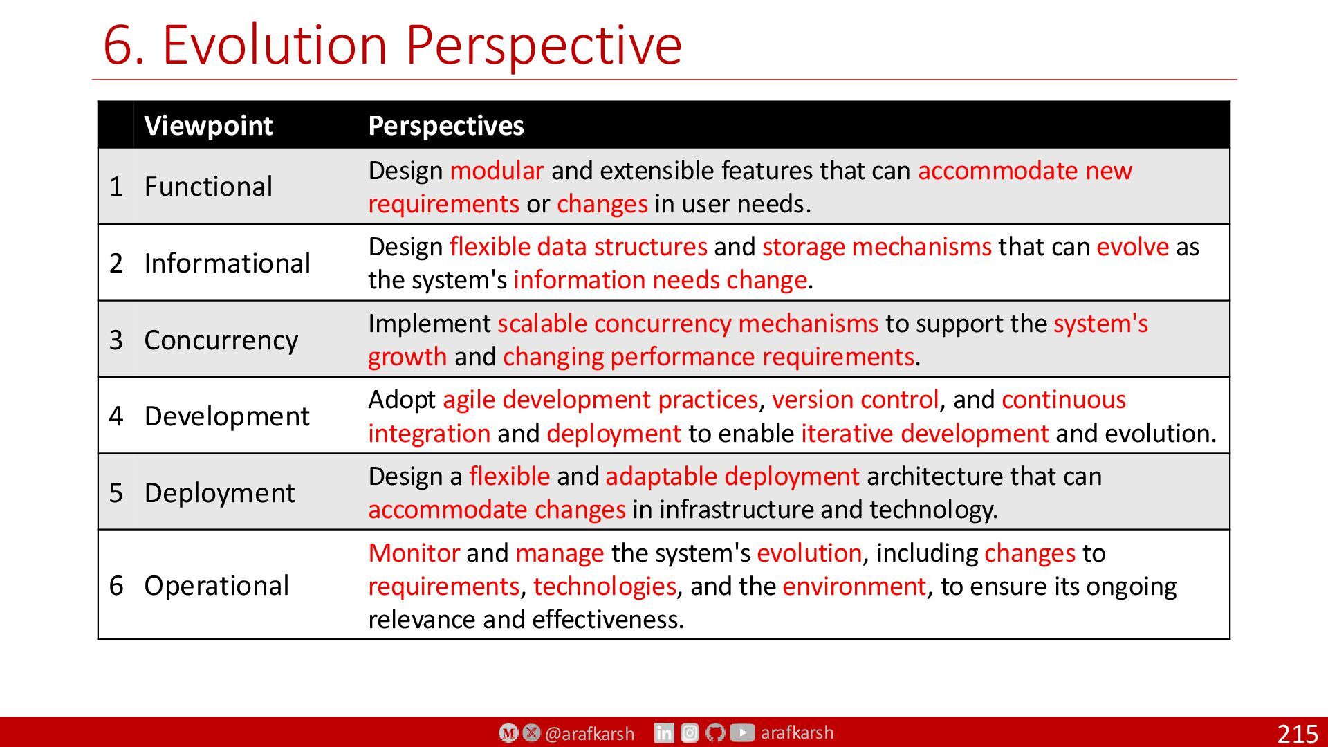
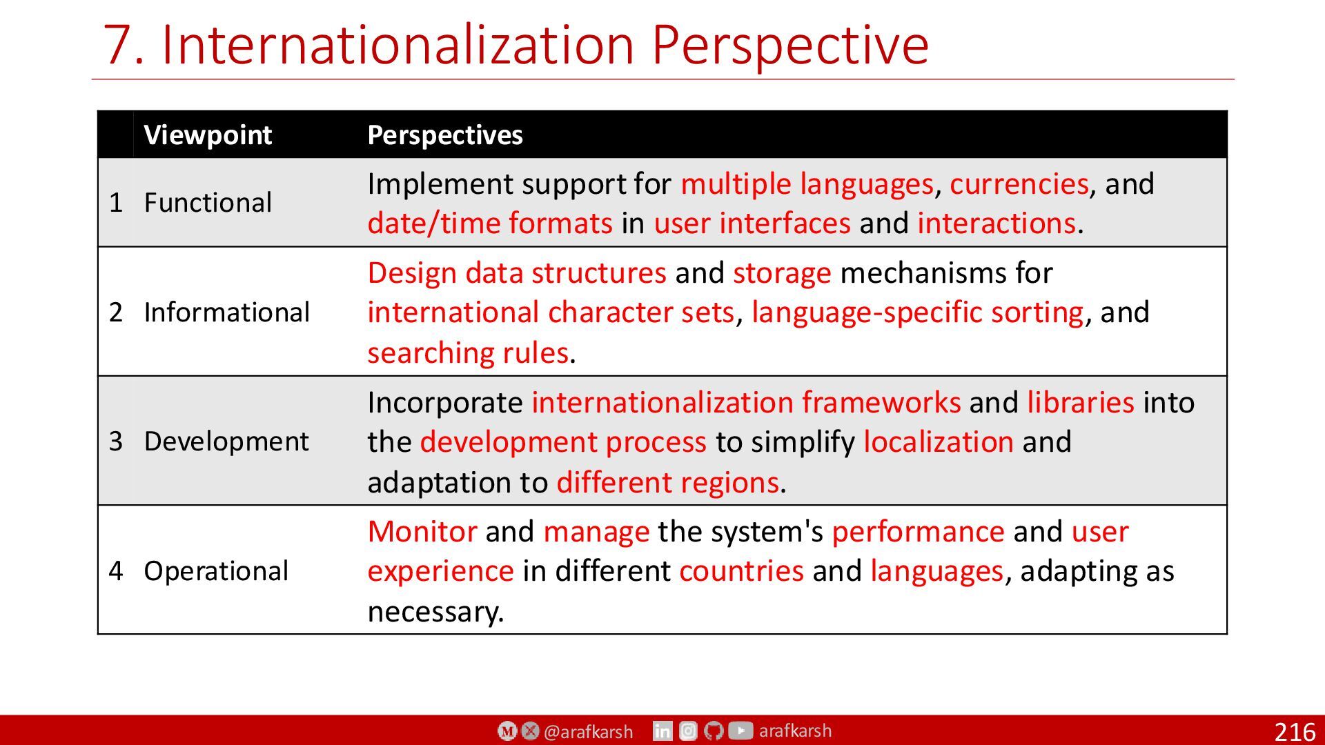
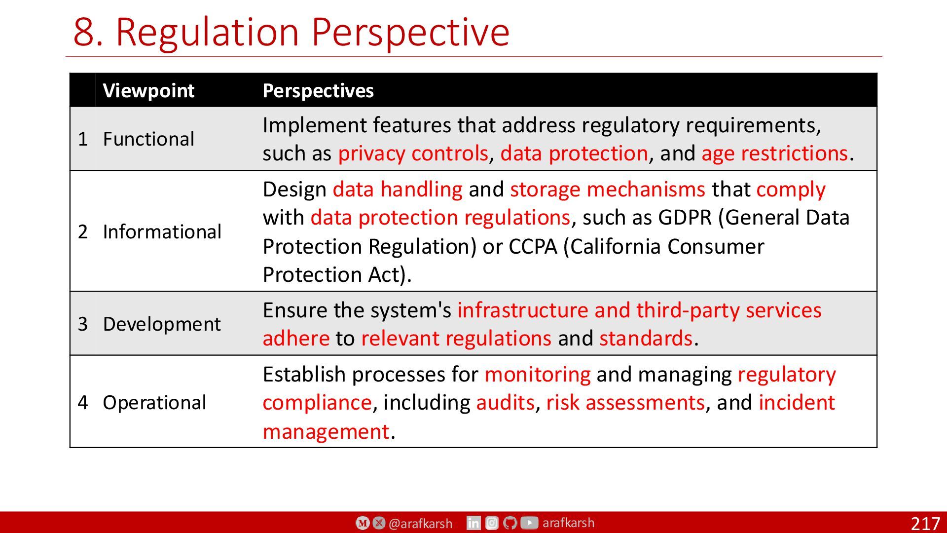
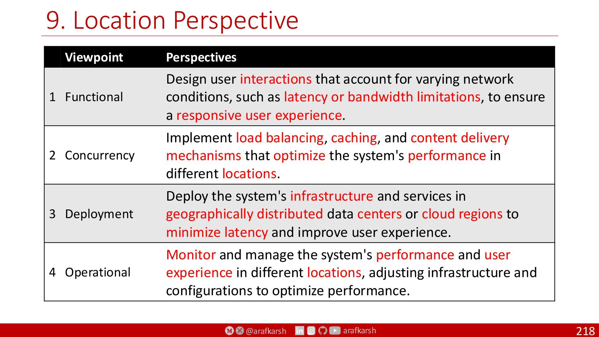
Views, Viewpoints, Perspectives
To Manage
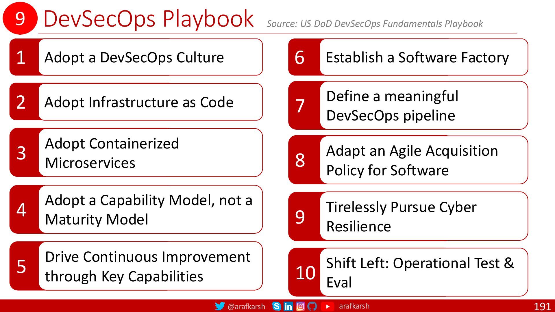
SpecOps: From Specs to Ops
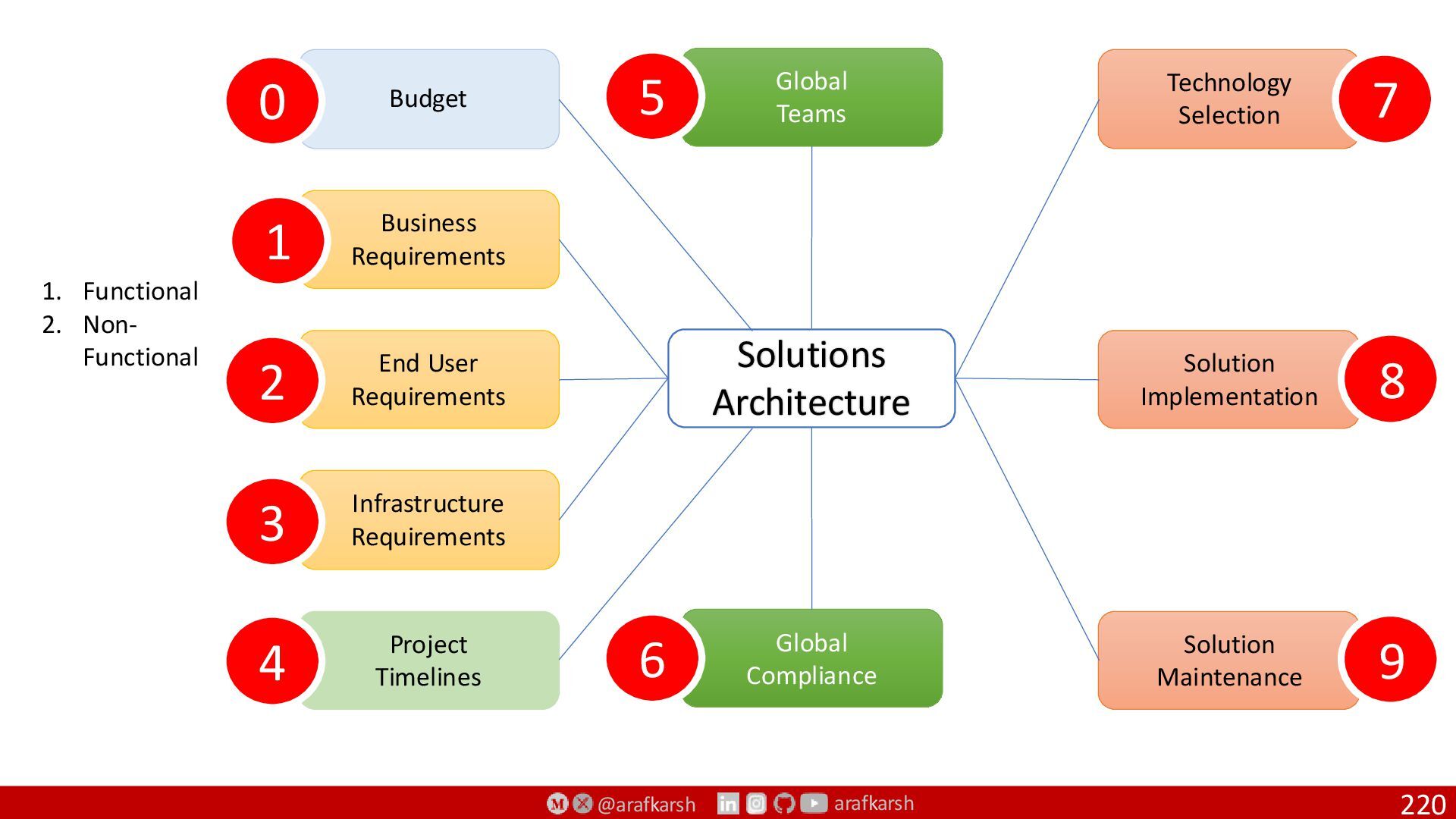
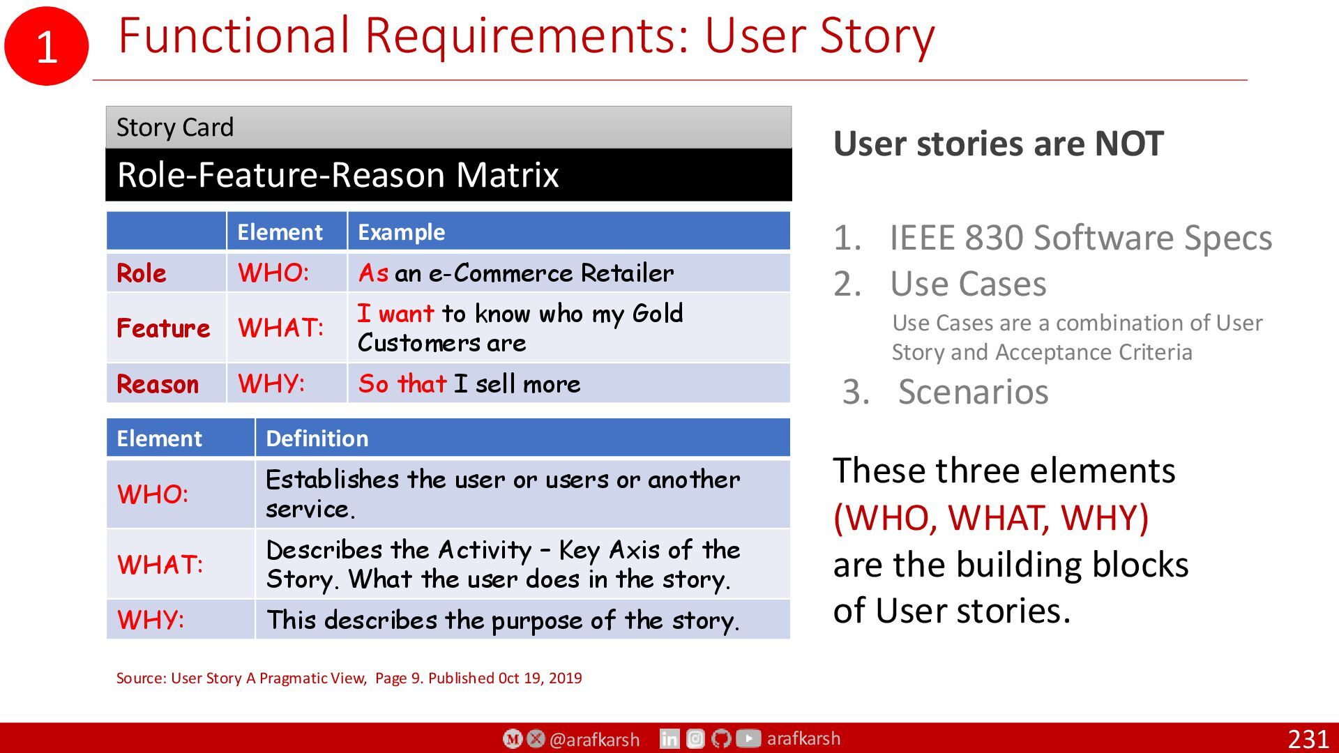
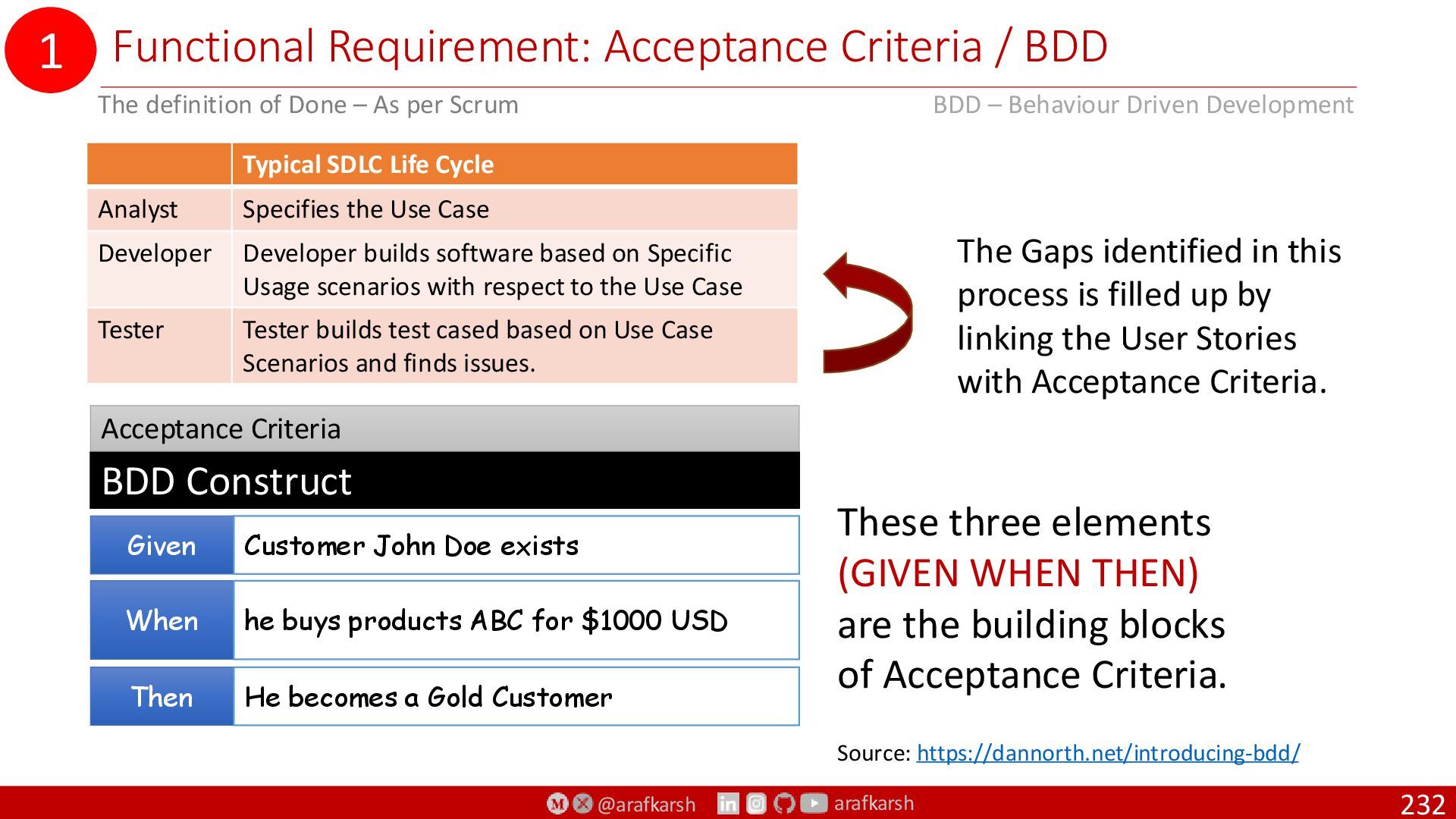
1. Business Requirements
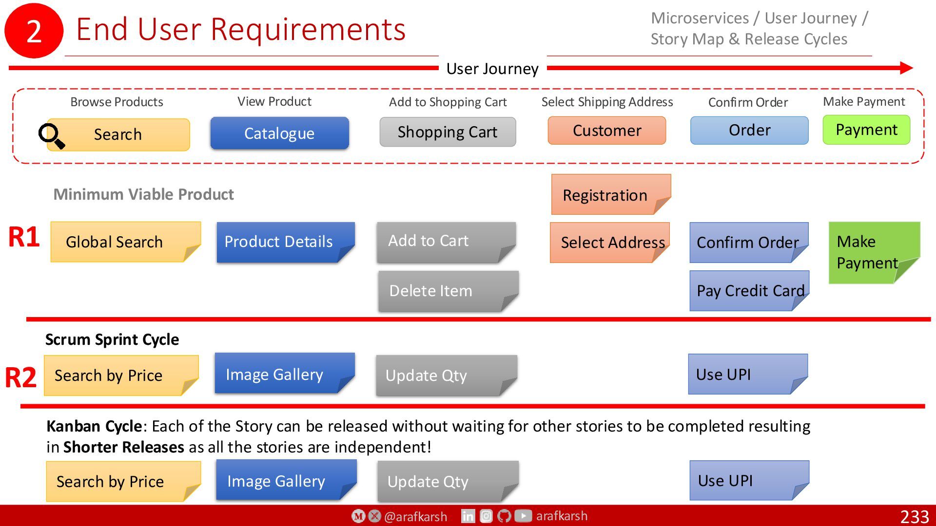
2. End-user Requirements
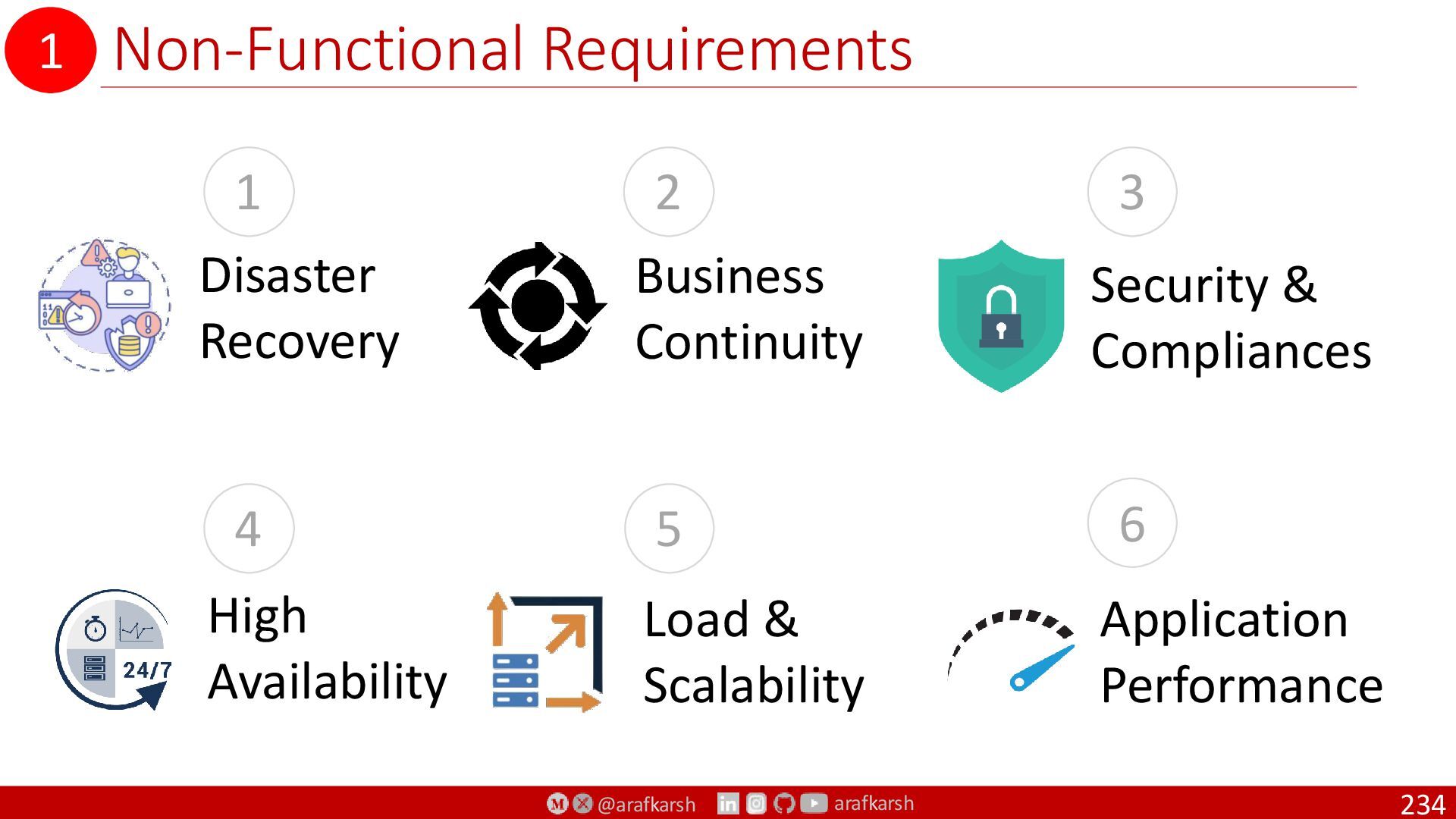
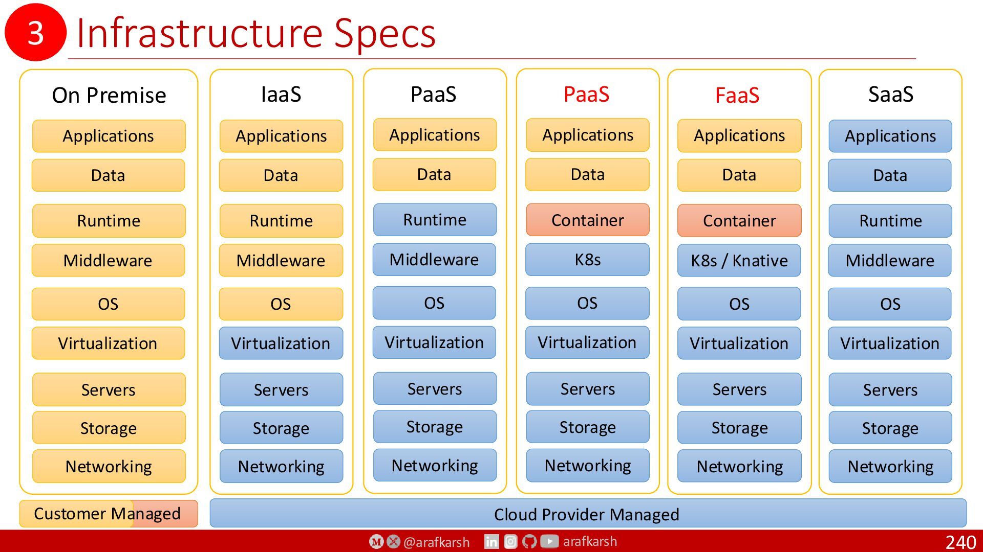
3. Infrastructure Requirements
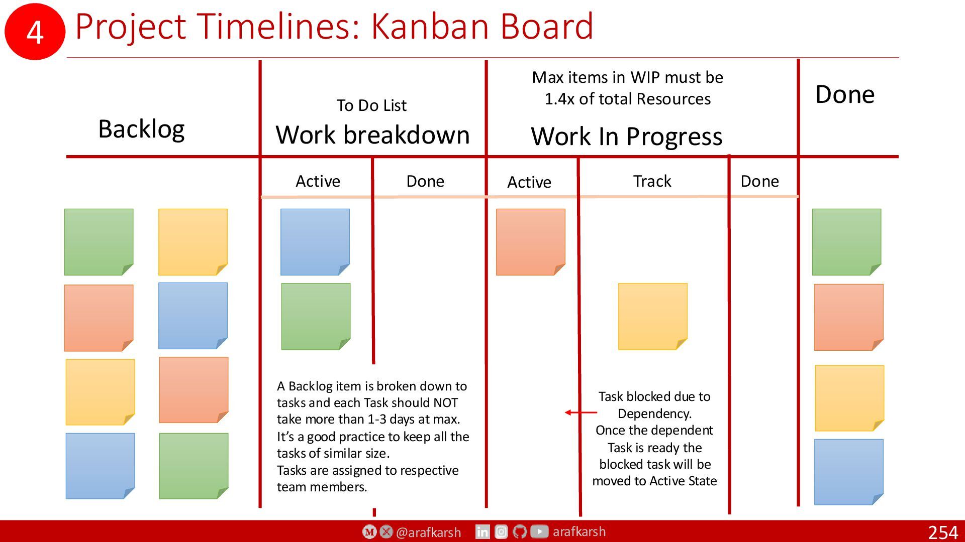
4. Project Timelines
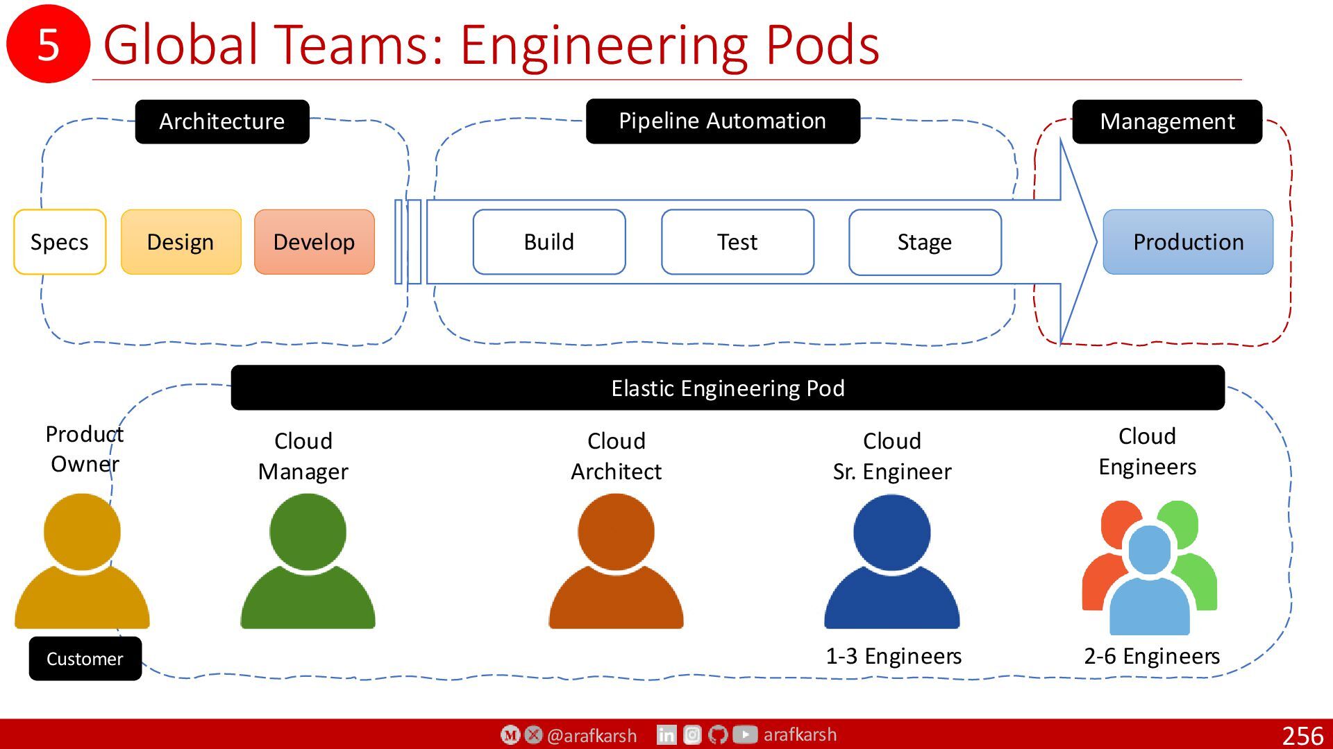
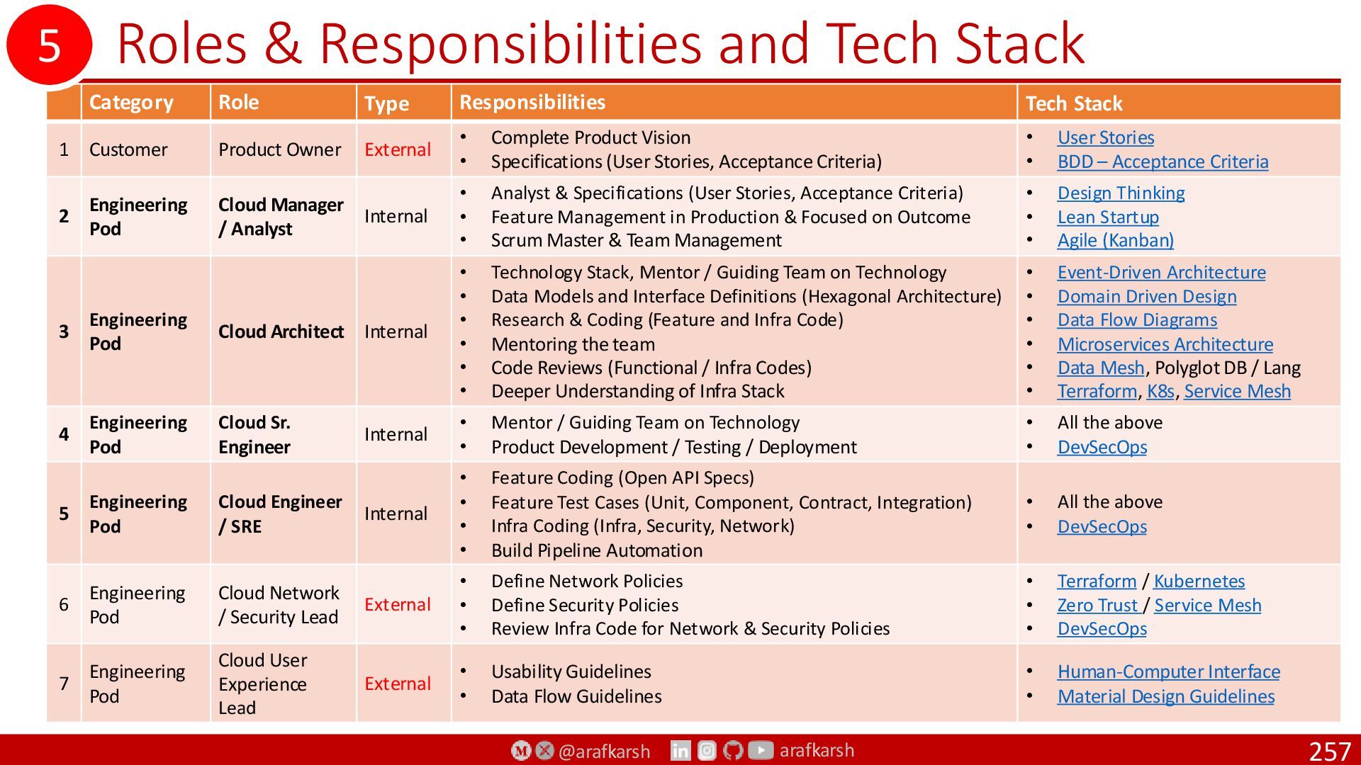
5. Global Teams
6. Global Compliance
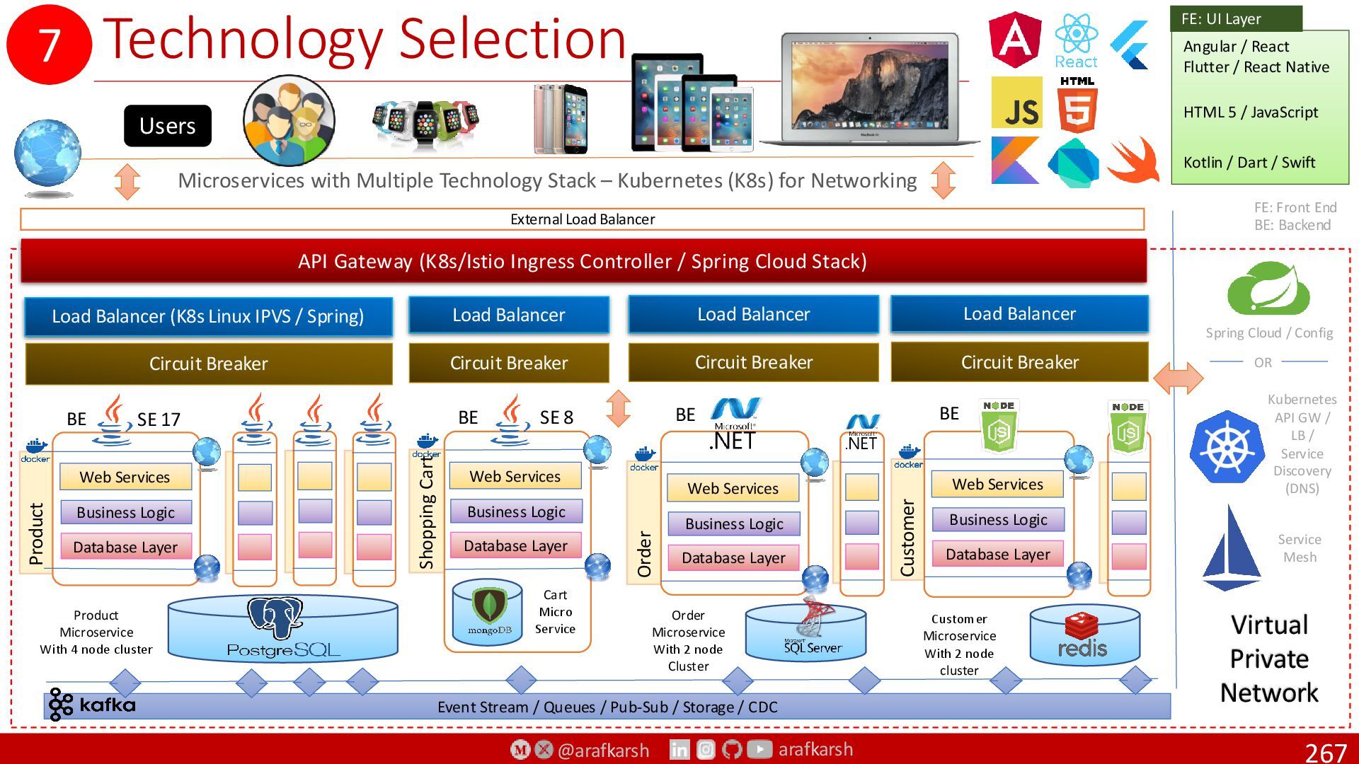
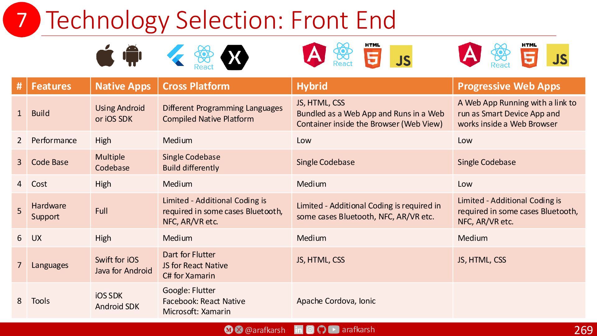
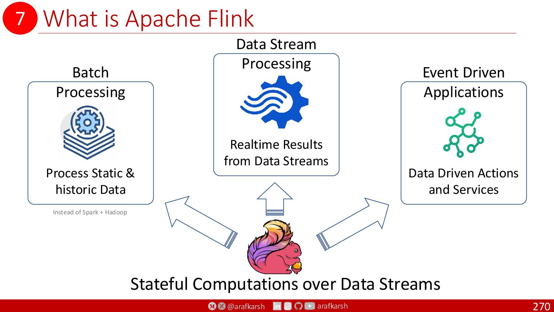
7. Technology Selection
8. Solution Implementation
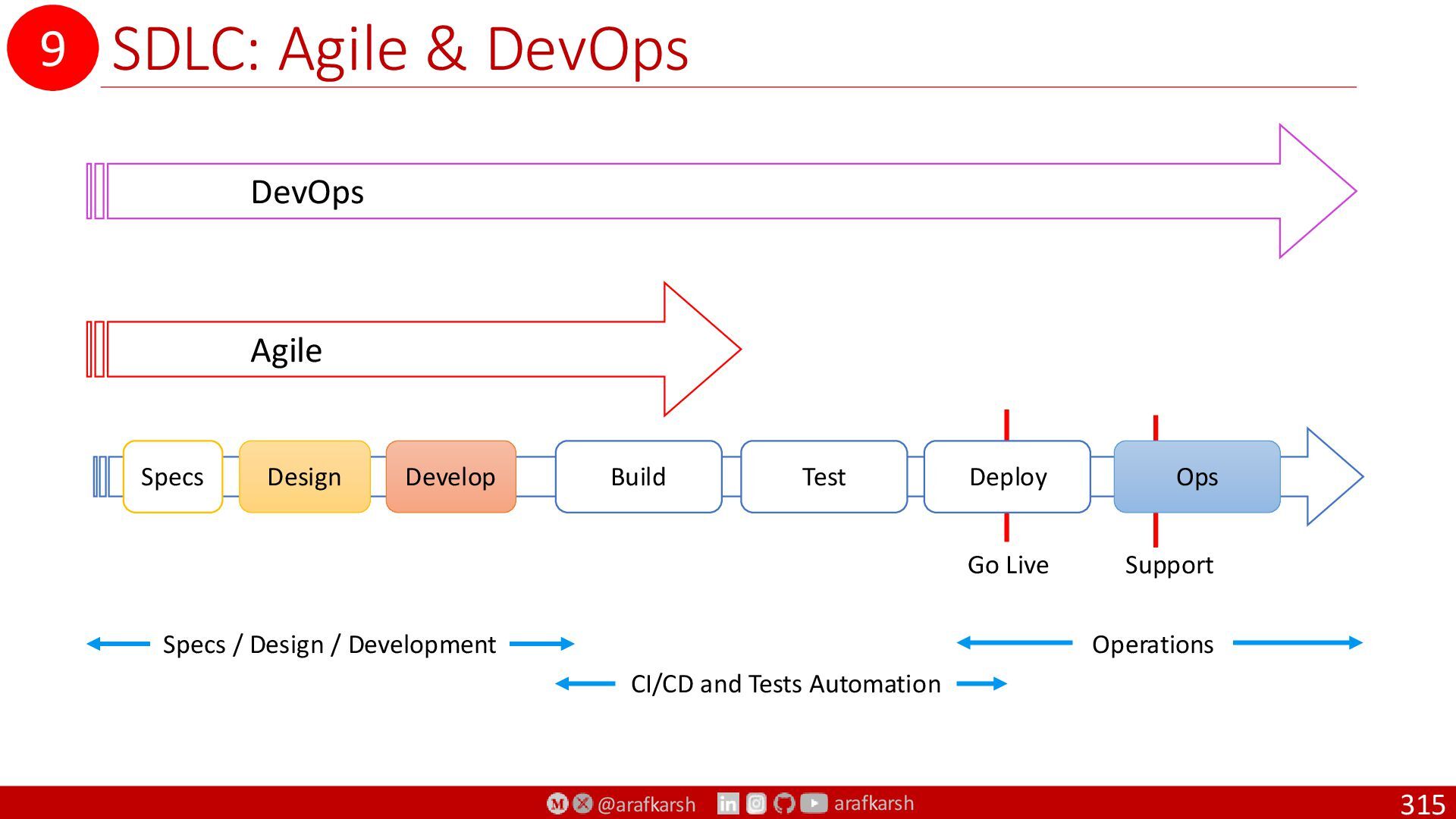
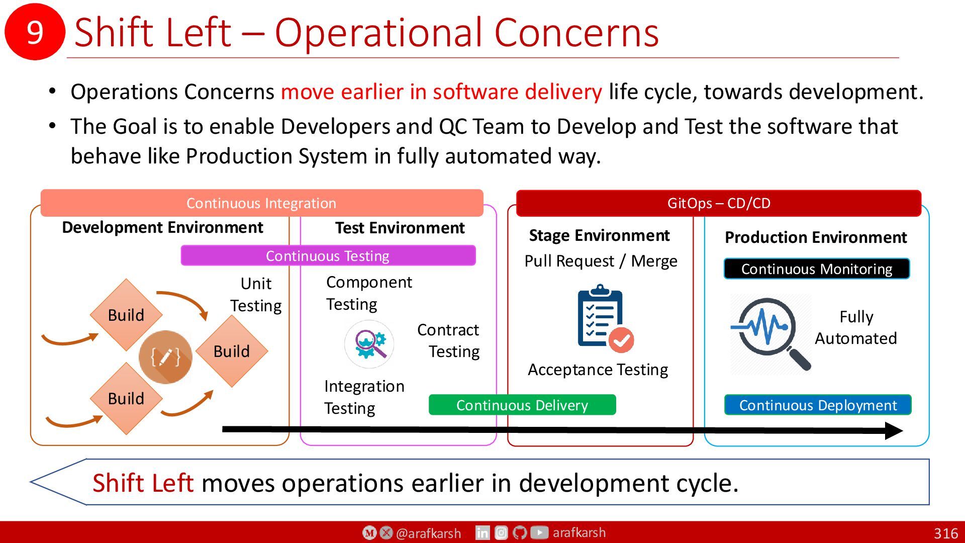
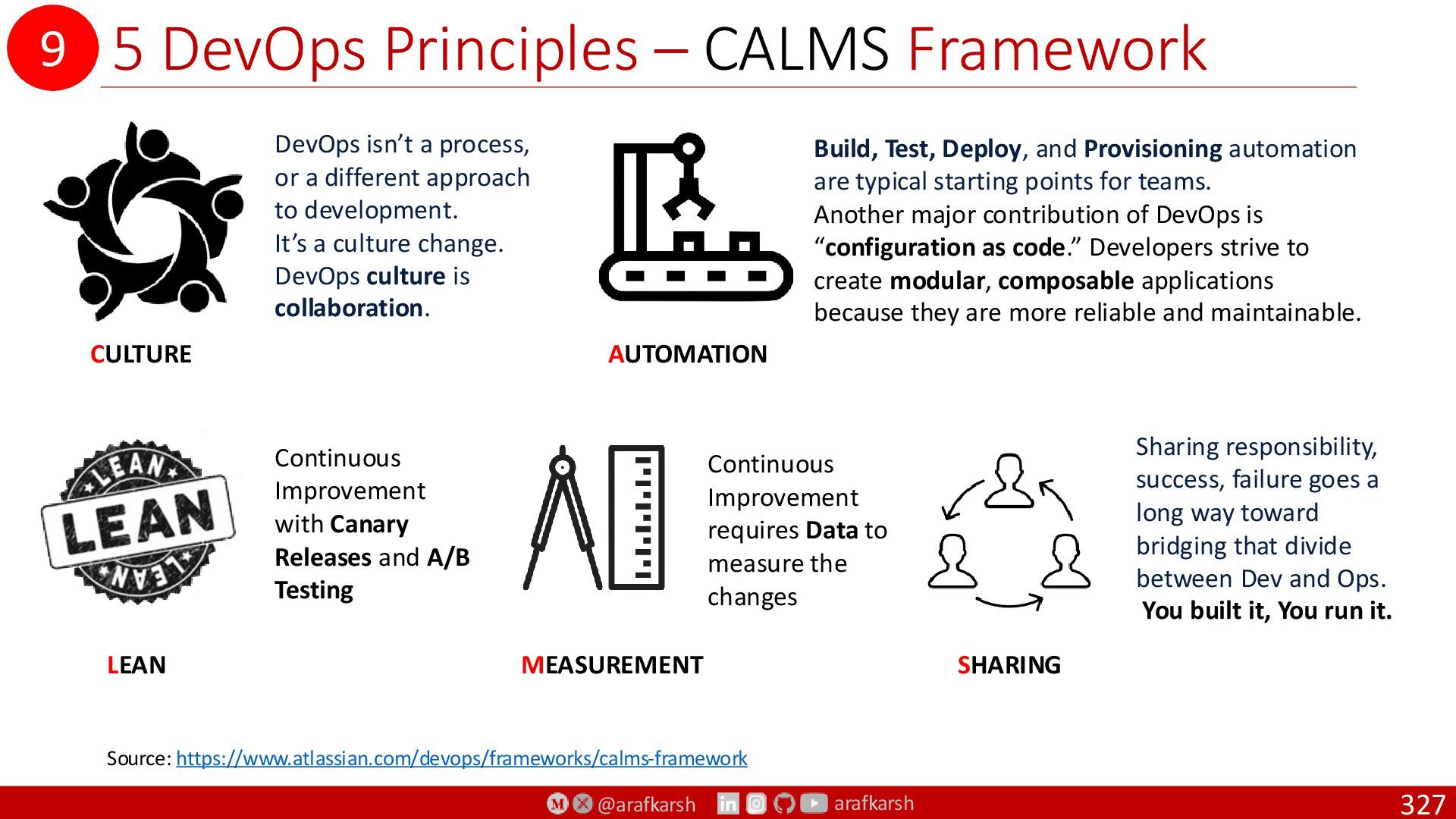
9. Solution Maintenance