Upgrade to Pro — share decks privately, control downloads, hide ads and more …

Presentation of Transportation Engineering Anal...

Presentation of Transportation Engineering Analysis Details

Transportation engineering or transport engineering is the application of technology and scientific principles to the planning, functional design, operation and management of facilities for any mode of transportation in order to provide for the safe, efficient, rapid, comfortable, convenient, economical, and environmentally compatible movement of people and goods transport.

The planning aspects of transportation engineering relate to elements of urban planning, and involve technical forecasting decisions and political factors. Technical forecasting of passenger travel usually involves an urban transportation planning model, requiring the estimation of trip generation (number of purposeful trips), trip distribution (destination choice, where the traveler is going), mode choice (mode that is being taken), and route assignment (the streets or routes that are being used). More sophisticated forecasting can include other aspects of traveler decisions, including auto ownership, trip chaining (the decision to link individual trips together in a tour) and the choice of residential or business location (known as land use forecasting). Passenger trips are the focus of transportation engineering because they often represent the peak of demand on any transportation system.

A review of descriptions of the scope of various committees indicates that while facility planning and design continue to be the core of the transportation engineering field, such areas as operations planning, logistics, network analysis, financing, and policy analysis are also important, particularly to those working in highway and urban transportation. The National Council of Examiners for Engineering and Surveying (NCEES) list online the safety protocols, geometric design requirements, and signal timing.

Transportation engineering, primarily involves planning, design, construction, maintenance, and operation of transportation facilities. The facilities support air, highway, railroad, pipeline, water, and even space transportation. The design aspects of transportation engineering include the sizing of transportation facilities (how many lanes or how much capacity the facility has), determining the materials and thickness used in pavement designing the geometry (vertical and horizontal alignment) of the roadway (or track).

Before any planning occurs an engineer must take what is known as an inventory of the area or, if it is appropriate, the previous system in place. This inventory or database must include information on population, land use, economic activity, transportation facilities and services, travel patterns and volumes, laws and ordinances, regional financial resources, and community values and expectations. These inventories help the engineer create business models to complete accurate forecasts of the future conditions of the system.

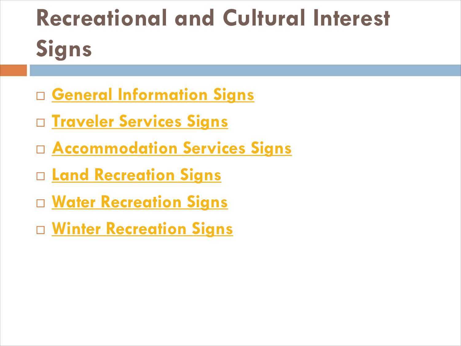
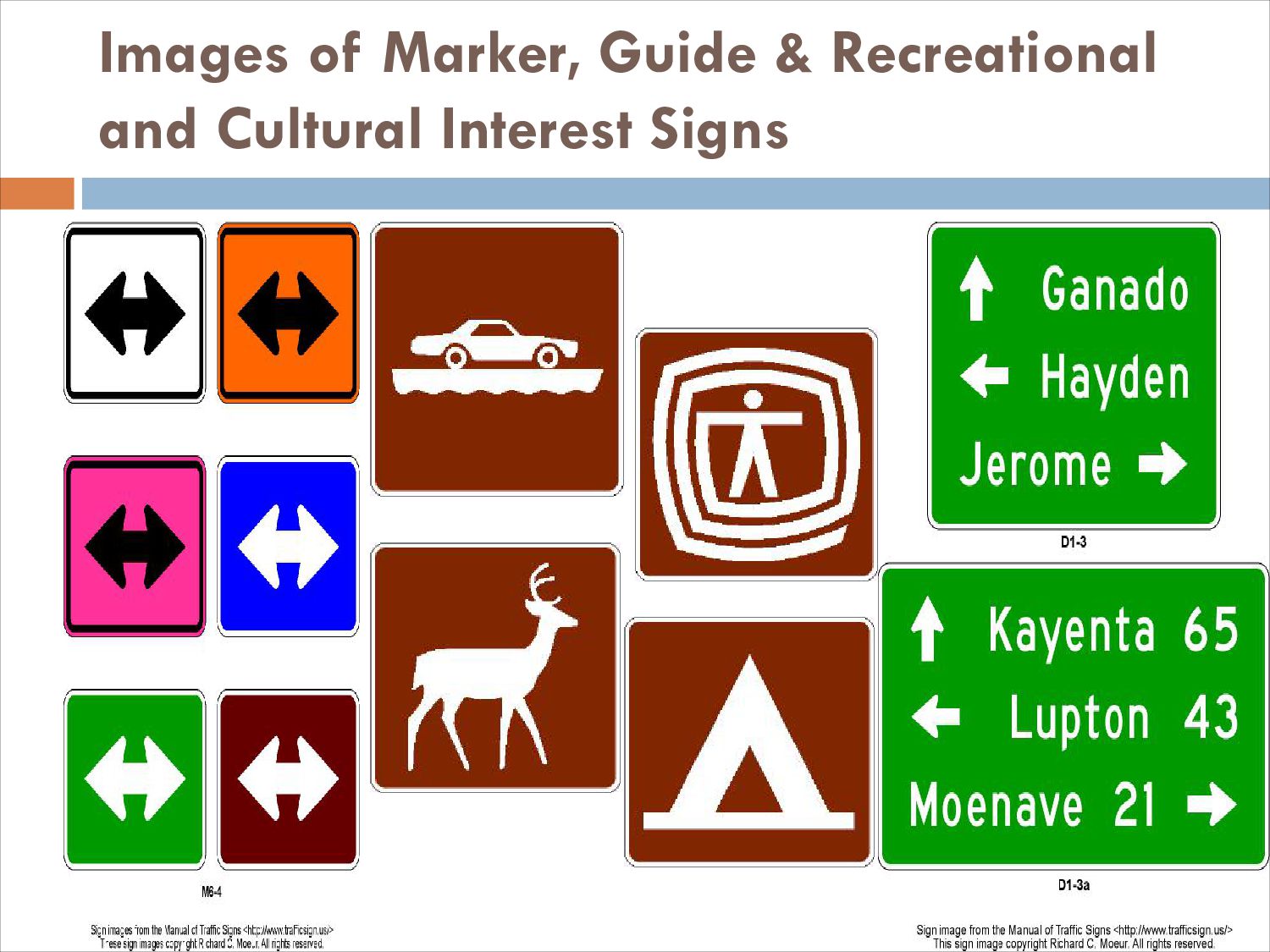
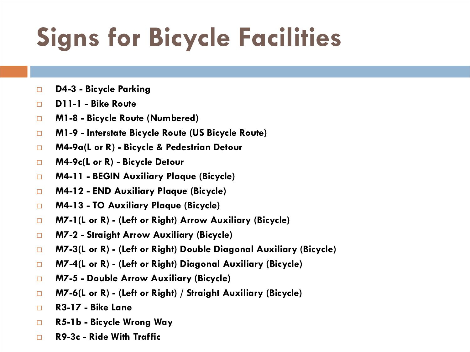
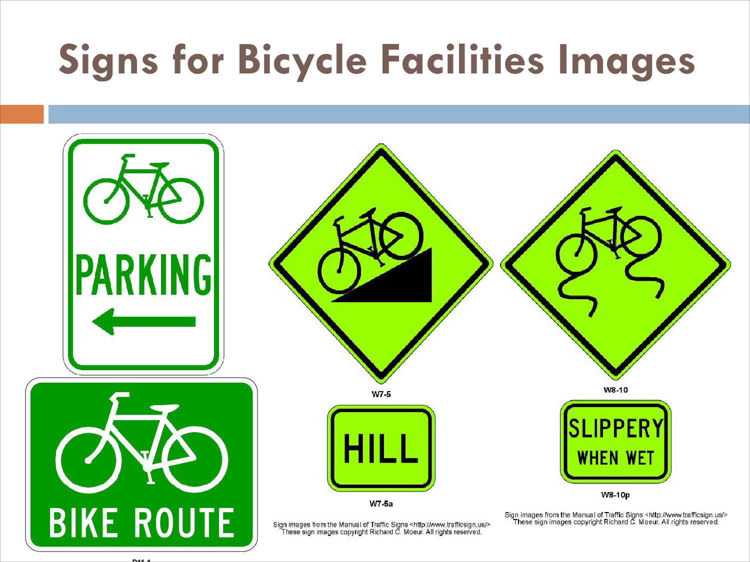
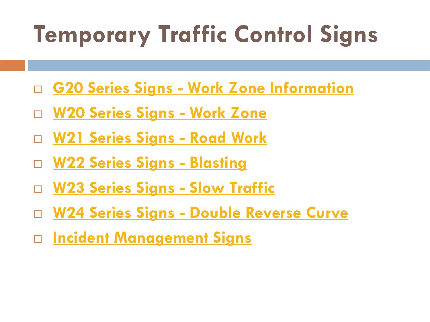
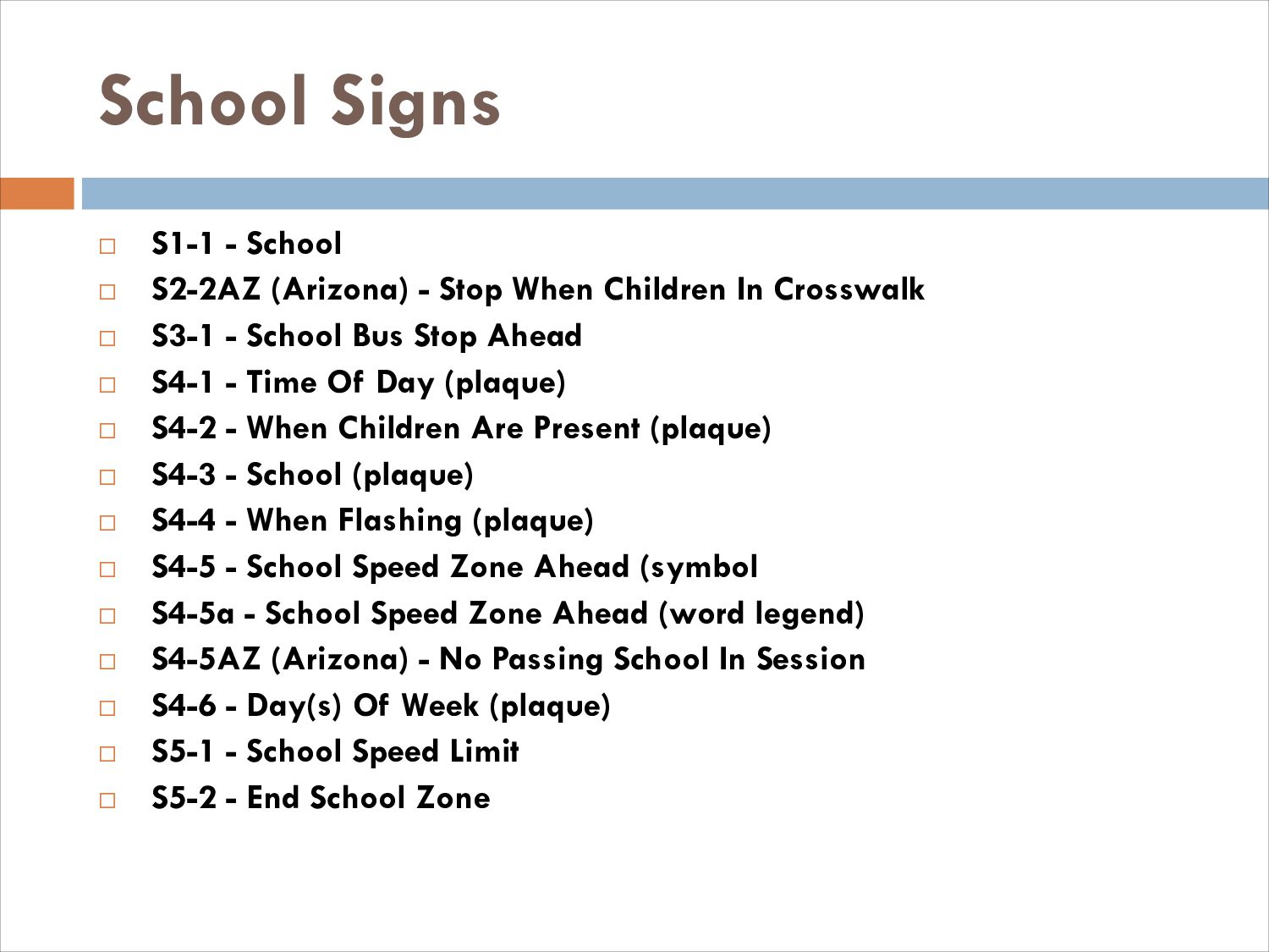
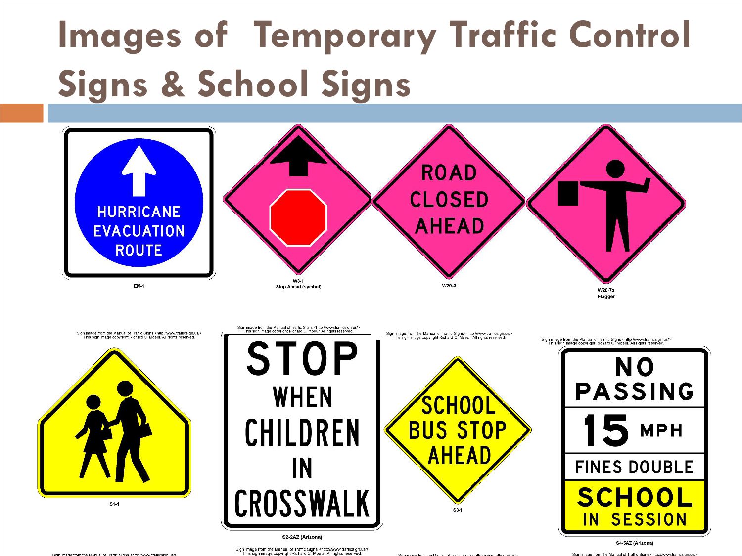
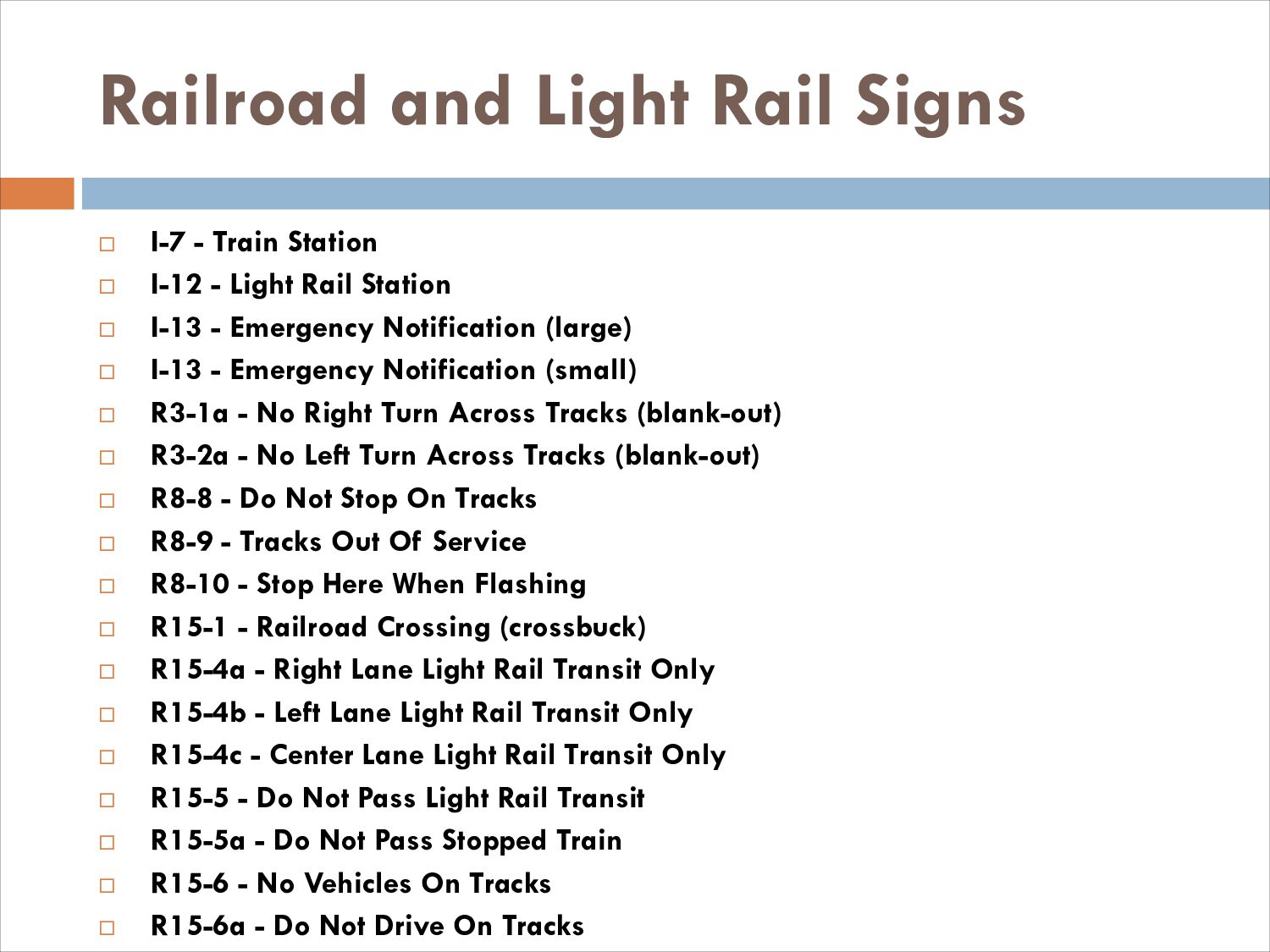
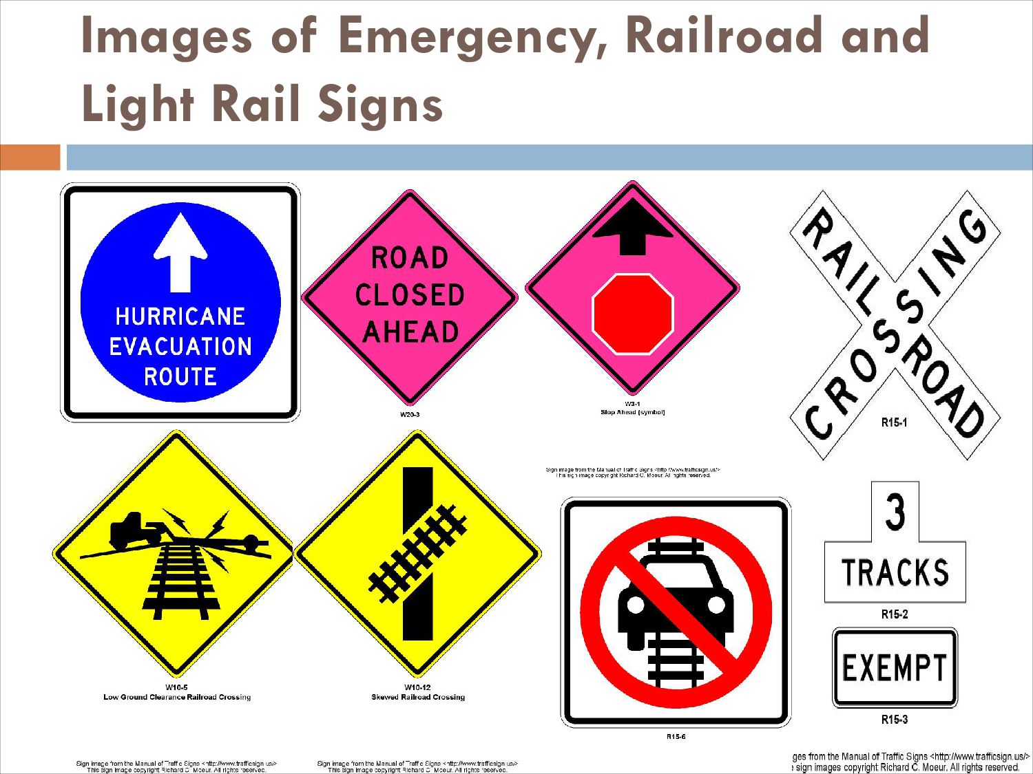
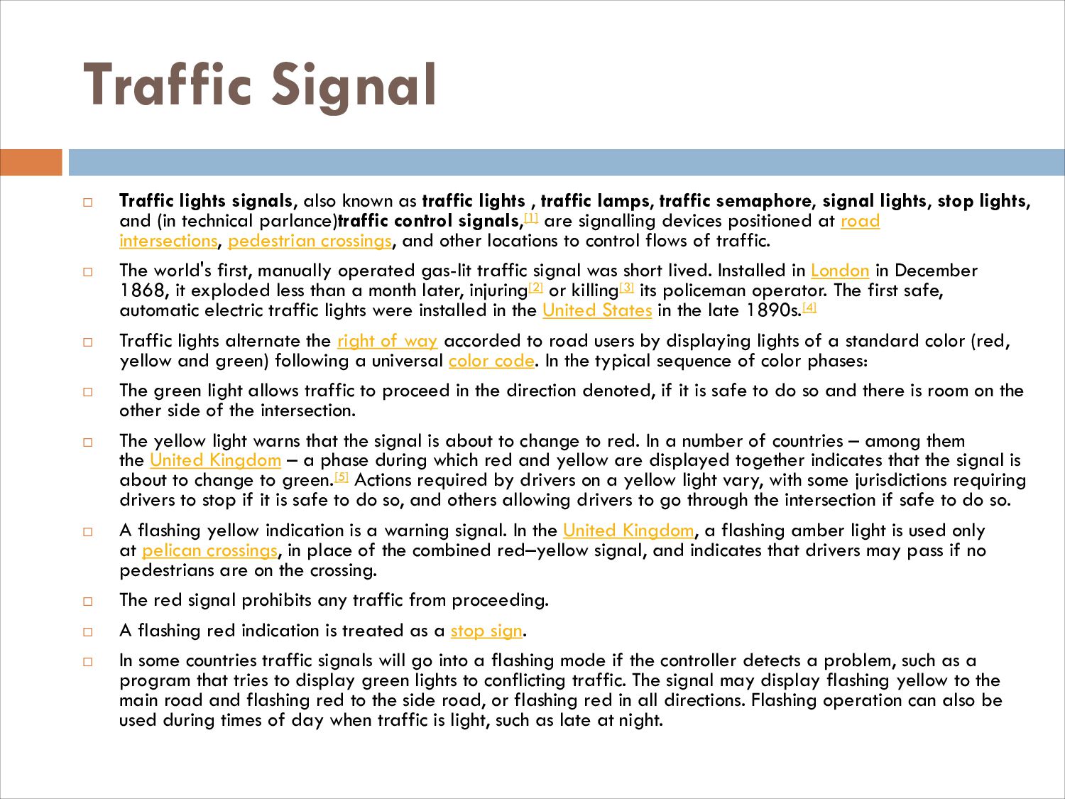
Operations and management involve traffic engineering, so that vehicles move smoothly on the road or track. Older techniques include signs, signals, markings, and tolling. Newer technologies involve intelligent transportation systems, including advanced traveler information systems (such as variable message signs), advanced traffic control systems (such as ramp meters), and vehicle infrastructure integration. Human factors are an aspect of transportation engineering, particularly concerning driver-vehicle interface and user interface of road signs, signals, and markings.
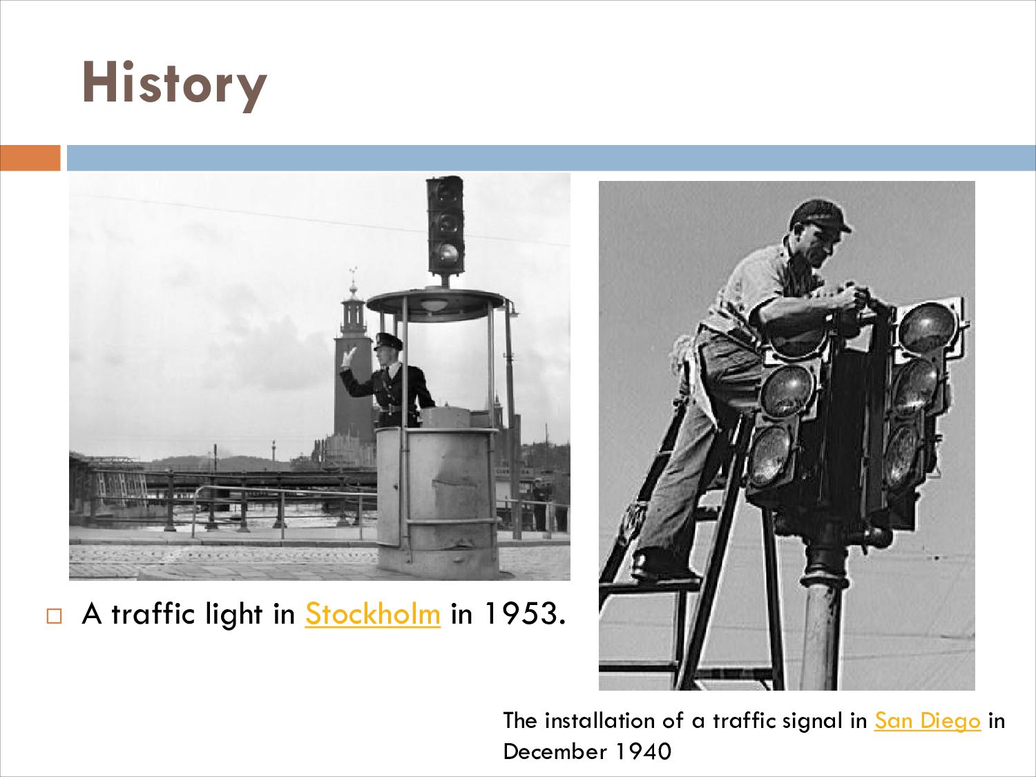
Avatar for Avijit Krishna Sushil

Avijit Krishna Sushil

August 05, 2023
Tweet

More Decks by Avijit Krishna Sushil

Other Decks in Research

Transcript

  1. Presentation About  Sign  Signal  Road Classification Of

    Transportation Systems in Bangladesh & All Over the World
  2. Presented To S M Rahat Rahaman Lecturer Department of Civil

    Engineering Port City International University, Chittagong.
  3. Traffic Sign  A sign conveying information, an instruction, or

    a warning to drivers.  Traffic signs or road signs are signs erected at the side of or above roads to give instructions or provide information to road users. The earliest signs were simple wooden or stone milestones. Later, signs with directional arms were introduced, for example, the fingerposts in the United Kingdom and their wooden counterparts in Saxony.  With traffic volumes increasing since the 1930s, many countries have adopted pictorial signs or otherwise simplified and standardized their signs to overcome language barriers, and enhance traffic safety. Such pictorial signs use symbols (often silhouettes) in place of words and are usually based on international protocols. Such signs were first developed in Europe, and have been adopted by most countries to varying degrees.
  4. History  The earliest road signs were milestones, giving distance

    or direction; for example, the Romans erected stone columns throughout their empire giving the distance to Rome. In the Middle Ages, multidirectional signs at intersections became common, giving directions to cities and towns.  In 1686, the first known Traffic Regulation Act in Europe is established by King Peter II of Portugal. This act foresees the placement of priority signs in the narrowest streets of Lisbon, stating which traffic should back up to give way. One of these signs still exists at Salvador street, in the neighborhood of Alfama.  The first modern road signs erected on a wide scale were designed for riders of high or "ordinary" bicycles in the late 1870s and early 1880s. These machines were fast, silent and their nature made them difficult to control, moreover their riders travelled considerable distances and often preferred to tour on unfamiliar roads. For such riders, cycling organizations began to erect signs that warned of potential hazards ahead (particularly steep hills), rather than merely giving distance or directions to places, thereby contributing the sign type that defines "modern" traffic signs.  The development of automobiles encouraged more complex signage systems using more than just text-based notices. One of the first modern-day road sign systems was devised by the Italian Touring Club in 1895. By 1900, a Congress of the International League of Touring Organizations in Paris was considering proposals for standardization of road signage. In 1903 the British government introduced four "national" signs based on shape, but the basic patterns of most traffic signs were set at the 1908 International Road Congress inParis.[citation needed] In 1909, nine European governments agreed on the use of four pictorial symbols, indicating "bump", "curve", "intersection", and "grade-level railroad crossing". The intensive work on international road signs that took place between 1926 and 1949 eventually led to the development of the European road sign system. Both Britain and the United States developed their own road signage systems, both of which were adopted or modified by many other nations in their respective spheres of influence. The UK adopted a version of the European road signs in 1964 and, over past decades, North American signage began using some symbols and graphics mixed in with
  5. History Roman milestone 17th century traffic sign in Salvador street,

    Lisbon, Portugal stating which traffic should back up to give way: Year of 1686. His Majesty commands all coaches, carriages and litters coming from Salvador's entrance to back up to the same part
  6. Categories  Traffic signs can be grouped into several types.

    For example, Annexe 1 of the Vienna Convention on Road Signs and Signals (1968), which on 30 June 2004 had 52 signatory countries, defines eight categories of signs:  A. Danger warning signs  B. Priority signs  C. Prohibitory or restrictive signs  D. Mandatory signs  E. Special regulation signs  F. Information, facilities, or service signs  G. Direction, position, or indication signs  H. Additional panels
  7. Categories  In the United States, Canada, Ireland, Australia, and

    New Zealand signs are categorized as follows:  Regulatory signs  Warning signs  Guide signs  Street name signs  Route marker signs  Expressway signs  Freeway signs  Welcome signs  Informational signs  Recreation and cultural interest signs
  8. Categories  Emergency management (civil defense) signs  Temporary traffic

    control (construction or work zone) signs  School signs  Railroad and light rail signs  Bicycle signs
  9. Regulatory Signs  R1 Series Signs - STOP and YIELD

     R2 Series Signs - Speed Regulation  R3 Series Signs - Turn & Lane Use  R4 Series Signs - Movement Regulation  R5 Series Signs - Selective Exclusion  R6 Series Signs - One Way / Divided Highway Crossing  R7 Series Signs - Parking Regulation  R8 Series Signs - Parking Prohibition & Emergency Restriction  R9 Series Signs - Pedestrian & Bicycle  R10 Series Signs - Traffic Signal  R11 Series Signs - Road Closed  R12 Series Signs - Weight Limit  R13 Series Signs - Weigh Station  R14 Series Signs - Truck Route  R15 Series Signs - Railroad & Light Rail  R16 Series Signs - Seat Belt
  10. Warning Signs  W1 Series Signs - Turn and Curve

     W2 Series Signs - Intersection  W3 Series Signs - Advance Traffic Control  W4 Series Signs - Merge and Lane Transition  W5 Series Signs - Width Restriction  W6 Series Signs - Divided Highway  W7 Series Signs - Hill  W8 Series Signs - Pavement Condition  W9 Series Signs - Lane Transition  W10 Series Signs - Railroad and Light Rail  W11 Series Signs - Advance Warning / Crossing  W12 Series Signs - Low Clearance  W13 Series Signs - Advisory Speed  W14 Series Signs - Dead End / No Outlet / No Passing  W15 Series Signs - Playground  W16 Series Signs - Supplemental Plaques  W17 Series Signs - Speed Hump
  11. Marker Signs  M1 Series Signs - Route Markers 

    M2 Series Signs - Junction Signs  M3 Series Signs - Cardinal Direction Auxiliaries  M4 Series Signs - Alternative Route Signs  M5 Series Signs - Advance Turn Auxiliaries  M6 Series Signs - Directional Arrow Auxiliaries  M7 Series Signs - Directional Arrow Auxiliaries (Bicycle)
  12. Guide Signs  D Series Signs - Destination and Distance

     E Series Signs - Expressway and Freeway  G20 Series Signs - Work Zone Information  I Series Signs - General Information  Recreational and Cultural Interest
  13. Recreational and Cultural Interest Signs  General Information Signs 

    Traveler Services Signs  Accommodation Services Signs  Land Recreation Signs  Water Recreation Signs  Winter Recreation Signs
  14. Signs for Bicycle Facilities  D4-3 - Bicycle Parking 

    D11-1 - Bike Route  M1-8 - Bicycle Route (Numbered)  M1-9 - Interstate Bicycle Route (US Bicycle Route)  M4-9a(L or R) - Bicycle & Pedestrian Detour  M4-9c(L or R) - Bicycle Detour  M4-11 - BEGIN Auxiliary Plaque (Bicycle)  M4-12 - END Auxiliary Plaque (Bicycle)  M4-13 - TO Auxiliary Plaque (Bicycle)  M7-1(L or R) - (Left or Right) Arrow Auxiliary (Bicycle)  M7-2 - Straight Arrow Auxiliary (Bicycle)  M7-3(L or R) - (Left or Right) Double Diagonal Auxiliary (Bicycle)  M7-4(L or R) - (Left or Right) Diagonal Auxiliary (Bicycle)  M7-5 - Double Arrow Auxiliary (Bicycle)  M7-6(L or R) - (Left or Right) / Straight Auxiliary (Bicycle)  R3-17 - Bike Lane  R5-1b - Bicycle Wrong Way  R9-3c - Ride With Traffic
  15. Temporary Traffic Control Signs  G20 Series Signs - Work

    Zone Information  W20 Series Signs - Work Zone  W21 Series Signs - Road Work  W22 Series Signs - Blasting  W23 Series Signs - Slow Traffic  W24 Series Signs - Double Reverse Curve  Incident Management Signs
  16. School Signs  S1-1 - School  S2-2AZ (Arizona) -

    Stop When Children In Crosswalk  S3-1 - School Bus Stop Ahead  S4-1 - Time Of Day (plaque)  S4-2 - When Children Are Present (plaque)  S4-3 - School (plaque)  S4-4 - When Flashing (plaque)  S4-5 - School Speed Zone Ahead (symbol  S4-5a - School Speed Zone Ahead (word legend)  S4-5AZ (Arizona) - No Passing School In Session  S4-6 - Day(s) Of Week (plaque)  S5-1 - School Speed Limit  S5-2 - End School Zone
  17. Emergency and Incident Management Signs Emergency Management Signs (Civil Defense

    Signs)  EM-1 - Evacuation Route marker  EM-2 - Area Closed  EM-3 - Traffic Control Point  EM-4 - Maintain Top Safe Speed  EM-5 - Road Use Permit Required For Thru Traffic  EM-6a - Emergency Aid (Medical Center)  EM-6b - Emergency Aid (Welfare Center)  EM-6c - Emergency Aid (Registration Center)  EM-6d - Emergency Aid (Decontamination Center)  EM-7a - Emergency Shelter Incident Management Signs  M4-8 - Detour Route Auxiliary  M4-8b - End (Detour) Auxiliary  M4-9 - Detour (with arrow)  M4-10 - Detour Arrow  W1-6 - Large Arrow (one direction)  W3-1 - Stop Ahead (symbol)  W3-1a - Stop Ahead (word legend)  W3-4 - Be Prepared To Stop
  18. Railroad and Light Rail Signs  I-7 - Train Station

     I-12 - Light Rail Station  I-13 - Emergency Notification (large)  I-13 - Emergency Notification (small)  R3-1a - No Right Turn Across Tracks (blank-out)  R3-2a - No Left Turn Across Tracks (blank-out)  R8-8 - Do Not Stop On Tracks  R8-9 - Tracks Out Of Service  R8-10 - Stop Here When Flashing  R15-1 - Railroad Crossing (crossbuck)  R15-4a - Right Lane Light Rail Transit Only  R15-4b - Left Lane Light Rail Transit Only  R15-4c - Center Lane Light Rail Transit Only  R15-5 - Do Not Pass Light Rail Transit  R15-5a - Do Not Pass Stopped Train  R15-6 - No Vehicles On Tracks  R15-6a - Do Not Drive On Tracks
  19. Traffic Signal  Traffic lights signals, also known as traffic

    lights , traffic lamps, traffic semaphore, signal lights, stop lights, and (in technical parlance)traffic control signals,[1] are signalling devices positioned at road intersections, pedestrian crossings, and other locations to control flows of traffic.  The world's first, manually operated gas-lit traffic signal was short lived. Installed in London in December 1868, it exploded less than a month later, injuring[2] or killing[3] its policeman operator. The first safe, automatic electric traffic lights were installed in the United States in the late 1890s.[4]  Traffic lights alternate the right of way accorded to road users by displaying lights of a standard color (red, yellow and green) following a universal color code. In the typical sequence of color phases:  The green light allows traffic to proceed in the direction denoted, if it is safe to do so and there is room on the other side of the intersection.  The yellow light warns that the signal is about to change to red. In a number of countries – among them the United Kingdom – a phase during which red and yellow are displayed together indicates that the signal is about to change to green.[5] Actions required by drivers on a yellow light vary, with some jurisdictions requiring drivers to stop if it is safe to do so, and others allowing drivers to go through the intersection if safe to do so.  A flashing yellow indication is a warning signal. In the United Kingdom, a flashing amber light is used only at pelican crossings, in place of the combined red–yellow signal, and indicates that drivers may pass if no pedestrians are on the crossing.  The red signal prohibits any traffic from proceeding.  A flashing red indication is treated as a stop sign.  In some countries traffic signals will go into a flashing mode if the controller detects a problem, such as a program that tries to display green lights to conflicting traffic. The signal may display flashing yellow to the main road and flashing red to the side road, or flashing red in all directions. Flashing operation can also be used during times of day when traffic is light, such as late at night.
  20. History  On 9 December 1868,[7] the first, non-electric, gas-lit

    traffic lights were installed outside the Houses of Parliament in London to control the traffic in Bridge Street, Great George Street and Parliament Street. They were promoted by the railway engineer J. P. Knight and constructed by the railway signal engineers of Saxby & Farmer. The design combined three semaphore arms with red and green gas lamps for night-time use, on a pillar, operated by a police constable. The gas lantern was manually turned by a traffic police officer, with a lever at its base so that the appropriate light faced traffic.[8]  Although it was said to be successful at controlling traffic, its operational life was brief. It exploded on 2 January 1869, as a result of a leak in one of the gas lines underneath the sidewalk,[9] injuring[2] or killing[3] the policeman who was operating it. With doubts about its safety, the concept was abandoned until electric signals became available.  The first electric traffic light was developed in 1912 by Lester Wire, a policeman in Salt Lake City, Utah, who also used red-green lights.[10]On 5 August 1914, the American Traffic Signal Company installed a traffic signal system on the corner of East 105th Street and Euclid Avenue in Cleveland, Ohio.[11][12] It had two colors, red and green, and a buzzer, based on the design of James Hoge, to provide a warning for color changes. The design by James Hoge[13] allowed police and fire stations to control the signals in case of emergency. The first four- way, three-color traffic light was created by police officer William Potts in Detroit, Michigan in 1920.[14] Ashville, Ohio claims to be the home of the oldest working traffic light in the United States, used at an intersection of public roads from 1932 to 1982 when it was moved to a local museum.[15][16] Many pictures of historical traffic lights appear at a Traffic Signal Trivia page.[17]  The first interconnected traffic signal system was installed in Salt Lake City in 1917, with six connected intersections controlled simultaneously from a manual switch.[19] Automatic control of interconnected traffic lights was introduced March 1922 in Houston, Texas.[20]
  21. History  A traffic light in Stockholm in 1953. The

    installation of a traffic signal in San Diego in December 1940
  22. Traffic-light signalling and operation  The use of traffic lights

    to control the movement of traffic differs regionally and internationally in certain respects. This article describes some of these non-universal features. Note that the color phase commonly known as "yellow" is often referred to, especially in official usage, as "amber"; for consistency this article uses "yellow" throughout.
  23. Flashing beacons  In the United States, a flashing red

    light is the equivalent of a stop sign. In the United States and Australia, flashing yellow does not require traffic to stop, but drivers should exercise caution since opposing traffic may enter the intersection after stopping. This may be used when there is a malfunction with the signals, or late at night when there is little traffic. A single four-way flashing light showing only one color in each direction may be used at intersections where full three-color operation is not needed, but stop or yield signs alone have not had acceptable safety performance. Yellow lights are displayed to the main road, to highlight the intersection and inform drivers of the need for caution. Red lights supplement stop signs on the side road approaches. All-way red flashing lights can supplement all-way stop control, but all-way yellow beacons are prohibited by United States regulations.  In New Zealand, paired red/red traffic lights are often installed outside Fire and Ambulance Stations on major roads, which when activated by the station, flash alternatively (so that at any time one red light is always showing), the purpose being to cause to traffic to stop for a set amount of time to allow emergency vehicles to exit their station safely.  In some parts of Canada, a flashing green (known as Advanced Green) light signals permission for a left turn before the opposing traffic is allowed to enter the intersection, i.e., oncoming traffic is facing a RED light. Similarly, a flashing green may be an Extended Green, for left turns after the opposing traffic's full green phase. The flashing light may be a "full" green, or a green left arrow, both meaning the same thing. At least one traffic light in Montreal (on the Island of Montreal, 'Right-on-Red' is not allowed), has a flashing right- turn arrow, indicating that the pedestrian crossing has a red light, so it is safe to turn right and drive across it. At some intersections in Winnipeg, Manitoba, a flashing green right-turn arrow appears with a red light when traffic from the right has a green flashing left-turn arrow and is not allowed to make a U-turn. In other parts of the same country (e.g., Vancouver) a flashing green light conveys a very different meaning: the crossing road has stop signs with no lights of its own, and oncoming traffic also has a flashing green, not a red stop-light. This functions the same as a European "priority" sign (a yellow-and-white diamond shaped sign indicating that the current street is a Priority or "main" road, which cross streets must yield to at uncontrolled junctions, opposite to the usual arrangement in many European countries), for which there is no direct equivalent in North America.  The new US 2009 Manual on Uniform Traffic Control Devices specifically prohibits flashing any green signal indication.
  24. Unusual traffic light phases  Turn prohibition  Some signals

    have a special phase where there is a red light illuminated simultaneously with a green arrow. The meaning of this configuration is that a motorist may only proceed in the direction of the arrow. In the Province of Quebec, a signal may display a green straight arrow alone, usually for 5 to 9 seconds, and then the full green (or right turn arrow) illuminates. This allows pedestrians to engage into the roadway, and therefore (in theory) increases safety. Soldier's Field Road in Brighton, Massachusetts at the intersection with Nonantum Road, Birmingham Parkway and North Beacon Streets always has a red ball. Green arrows appear with the red ball to allow traffic to travel in a particular direction, but the red ball is always illuminated. The same is true at the intersection of Cambridge Street and Massachusetts Avenue near Harvard Square in Cambridge, Massachusetts, the intersection of Delaware Avenue at Harrison Street in Wilmington, Delaware, and at the intersection of West 3rd Street and Mesaba Avenue in Duluth, Minnesota. This is also true in Chicago, the straight off straight on ramps from Lake Shore Drive to N Fullerton Ave display a red light and left turn arrow or a red light, never just a green arrow.  On the island of Montréal, Québec, Canada, it is forbidden to turn right while a red signal is present. At many intersections, lights will change from red to a green arrow permitting drivers to proceed straight through the intersection. After approximately 5 seconds, the green arrow is replaced with a green ball signal allowing drivers to proceed forward or turn as they wish.  In the United States, some intersections have a three-lens signal without arrows with an adjoining three-lens signal (with arrows) governing exclusive left- or right-turns. Signals with circular lenses generally control all movements. At such intersections, the exclusive turn signals indicate that there are no permissive turn movements at that intersection, and that only exclusive turn movements are allowed. At those intersections, the signals with circular lenses govern movements in all directions except those in the direction which the turn signal controls. This means that if there is a left-turn signal and a circular-lens signal at an intersection, the latter signal controls right turns and straight movements, but not left turns. If the former signal is showing a red arrow, and the latter signal is showing a green ball, then motorists cannot turn left even though the latter light is showing a green ball.
  25. Unusual traffic light phases Indication of protected turn  Left

    and through signals on a 'J-arm' in Orinda, California  Throughout most of the United States a protected turn (a turn that can be made without conflicting traffic) is indicated by a steady burning 12-inch-diameter (300 mm) green arrow. This indication may be displayed in a separate traffic signal head or may be in combination with other arrows or a green ball indication on the same signal such as with the Dallas Phasing configuration described below. Modern signal standards require that a yellow "clearance" interval be displayed for not less than three seconds prior to the protected turn interval ending.  In parts of Canada (the Maritime Provinces, Quebec, Ontario, Saskatchewan and Alberta[2]), a flashing green light has a special meaning. It is only shown in one direction, with the other three directions in a 4-way intersection having a red light. It gives the traffic in its direction the right of way in all directions; straight through, left turn or right turn. This was done because the green arrow already had a different meaning in Ontario. It meant that all traffic must turn in the direction of the arrow.[3]  The light phase is known as "advanced green", and a sign saying "Advanced green when flashing" is usually attached to the light in question. The opposite side often has a sign attached to their lights saying "Delayed Green Wait for signal" or "Opposing Traffic Has Advanced Green." Advanced green indicates that the opposing traffic is facing a red light, and it is safe for the driver to turn left. Some of the signals had the turn phase after the oncoming green. They had signs saying "Extended green when flashing." This sequence had the hazard of yellow trap.  In Ontario, older lights with this system are slowly being phased out in favour of more universally understood left-turn arrow signals. In Alberta and Saskatchewan as a legacy, left-turn arrow signals also flash, rather than being displayed steadily as is done elsewhere.  In British Columbia, Alberta, Saskatchewan, Ontario, Quebec, New Brunswick and Nova Scotia, a flashing green arrow indicates that the opposing direction still has a red light (and any pedestrian crossing in that direction is at a "don't walk" indication), thus drivers are free to make a turn in the direction of the arrow. This is also used in most of the former British Commonwealth.  Protected flashing green is now used in parts of California[4] and Ontario as part of traffic signal preemption for emergency vehicles. This does not conform to the Manual on Uniform Traffic Control Devices.  In Ireland and the UK, a right arrow may be displayed alongside a green light to indicate that oncoming traffic has been stopped and that it is safe to turn right.  In Japan, they never show a green arrow with the circular green. Instead, green arrows must be shown with the circular red. This means a signal may display green arrows pointing in all possible directions with the circular red. Another unusual sequence is that the circular red changes to circular yellow whenever some or all of the arrows end, and then changes back to red after the clearance period.[5]
  26. Unusual traffic light phases Indication of permissive turn  Flashing

    yellow arrow  A pole-mounted flashing left turn signal in Oregon  A new configuration involving a flashing yellow arrow[6] has been introduced and is gaining acceptance across the US. This configuration prevents "yellow trap" when properly implemented. First observed in Oregon—and then elsewhere in the United States, like Fullerton, California;[7] Lawrence, Kansas; Tyler, Texas; Gainesville, Florida; across North Carolina; and New York City—the signals displaying a flashing yellow arrow are being phased in to replace the 5-lamp protected/permissive signals that are still in widespread use.  Four models of this signal exist. The one with 4 lamps is the most common. It has a steady red arrow, a steady yellow arrow, a flashing yellow arrow, and a steady green arrow. One rare version has five lenses, with a steady red arrow, two steady yellow arrows, a flashing yellow arrow, and a steady green arrow, and is only used sometimes, when there is a leading protected left turn. There are also two with 3 lamps. One signal has a steady red arrow, a steady yellow arrow, and a "dual indication" third lamp which can display either a steady green arrow or a flashing yellow arrow. The other 3-lamp signal has a steady red arrow, a steady yellow arrow and a flashing yellow arrow, with no green arrow; this can be used for either left or right turns, and is used to prevent yellow trap where no green arrow left turn phase exists on the approach. This cannot be done with the circular green without causing yellow trap, because a circular green releases other movements. The steady arrows all have their usual meanings. A flashing yellow arrow indicates a "permitted" left turn, where drivers may turn left without stopping (same as a Yield Sign), but opposing traffic has the right-of- way. The flashing yellow arrow must always be followed by either a steady yellow arrow or a steady green arrow.
  27. Indication of protected turn & permissive turn images  Left

    and through signals on a 'J-arm' in Orinda, California A pole-mounted flashing left turn signal in Oregon
  28. Dallas phasing  Horizontal Dallas display viewed from the left

    turn bay  In the configuration commonly known as Dallas phasing that began in the Dallas/Fort Worth Metroplex, the five-light left turn signal head is used in a different manner than standard signals of this type. The left turn signal head operates independently from the signals for straight through traffic. This allows permissive turning even when straight through traffic is shown a red light, avoiding yellow trap. Louvers are fitted over the green and yellow balls of the left turn signal head to prevent driver confusion. The left turn signal head is also accompanied by a sign indicating its special use.[15]  In this configuration, the left-turn signal will display circular green from the leading protected left turn phase until the lagging permissive left turn phase, but the green arrow will only be displayed during the leading protected left-turn phase. During the lagging permissive left-turn phase, it is assumed that opposing traffic has both a permissive left turn phase and a straight- through green light. This can also be used in the opposite configuration, with leading permissive and lagging protected left-turn phases.[15]  Doghouse Dallas display viewed from the left turn bay  Dallas phasing gives traffic engineers more flexibility with the leading and lagging protected left turn phase configurations allowing for better coordination between signals. There are also yellow and green arrows on Dallas phasing signals, permitting exclusive protected left-turn phases as well as protected/permissive left-turn phases.  The new 2009 Manual of Uniform Traffic Control Devices prohibits this display for new installations in favor of the flashing-yellow-arrow left-turn signal, which accommodates both permissive and protected left turns. Older installations are allowed to stay until they are replaced.[16]
  29. Images of Dallas phasing  Horizontal Dallas display viewed from

    the left turn bay Doghouse Dallas display viewed from the left turn bay
  30. No Turn Arrow  In Australia and New Zealand, an

    absent left or right turn arrow means traffic turning in the direction of the arrow may turn when the main light is green, provided they give way to pedestrians and other traffic.  In the state of Victoria, some intersections of this type employ a turn arrow without the red arrow. This would turn green with the main signal, before turning yellow, then off, giving priority to oncoming traffic. The nationwide standard seems to now include a red arrow that turns off. This arrow turns red simultaneously with the main light. After the cross traffic has had its turn, the arrows on opposite sides would both turn green, until one side runs out of right-turn traffic. In any case, when both sides of the intersection turn green, the corresponding arrow will turn off after a short delay, thus working similarly to the old Victorian standard. This method has the advantage of being controlled during peak-hours, where controllers would be able to prevent the arrow from turning off in extreme peak-hour traffic, but causes confusion as drivers expect a light to be on when three are present.  In New Zealand, red and yellow arrows (where fitted) always display regardless of the aspect main light. When a road is given a green light from an all-turn direction stop, a red arrow continues to display to turning traffic, holding traffic back while the pedestrian crossing on the side road is given a green signal. As soon as the pedestrian signal changes to flashing red, the red arrow extinguishes. Traffic turning may now proceed provided they give way to pedestrians and other traffic (oncoming traffic for right turns, right-turning traffic for left turns). This method is becoming common in many states of Australia. When an intersection is given a protected turn prior to the pedestrian crossing on the side road given the green signal, the lights change to yellow and red, and then the red arrow disappears as soon as the pedestrian crossing is given a flashing red signal.  The 5-light protected permissive signals in the US are the same.
  31. Images of No Turn Arrow An intersection in South Australia.

    This intersection uses the Protected/Permissive right turn explained here. If right-turn traffic on the opposite side runs out, then the main light on the facing side will turn green with the shown arrow (in the distance) remaining green until it runs out of right-turn traffic.
  32. Flashing Lights  Yellow arrow and ball  Around Richmond

    in Vancouver, British Columbia, some left turn signals use a dual-indication LED lamp; these signals display a green arrow, a yellow arrow in addition to a yellow ball, and a red ball. A traffic signal on the intersection of the Westminster Highway and Knight Street does the same with dual-indication through and right turn arrows. The yellow arrows are redundant, although they were also used where the yellow ball lamp had not yet been upgraded to an LED setup.  Crosswalks  Flashing green light  In British Columbia,[22] a flashing green globe signal is used at a pedestrian crossing or intersection, at which pedestrians have the ability to stop traffic to allow a safe crossing. They may also be used at a drawbridge. The flashing green indicates that the signal is not currently in use. After the pedestrian pushes the button to trigger the signal, the light becomes a steady green until the sequence of yellow, then red (at which time the pedestrian crossing gives a WALK signal) as in a conventional set of traffic lights, then returns to flashing green until another crossing is requested.[23]  In several European countries and Mexico, a flashing green light is used in crosswalks to indicate that signal is going to change from green to red soon. Therefore, flashing green has roughly the same meaning to pedestrians as ordinary yellow signal has for motorists. Slow-moving pedestrians are warned about oncoming signal change and have opportunity to wait for next signal cycle. Motorists are more likely to notice flashing signal. Drivers of vehicles about to cross pedestrian crossings should be more aware of incoming pedestrians.  Current users of flashing green signal are Austria, Belgium, Estonia, Finland, Great Britain, Hungary, Netherlands, Norway, Mexico, Poland, Spain and Sweden. France, Portugal and Switzerland make limited use of flashing green.  Flashing red lights[edit]  In Australia, New Zealand, Canada and most of the United States, a flashing red pedestrian signal is used at between green and steady red; it means "complete crossing but do not start to cross". This has a similar meaning to European flashing green, but means that if a pedestrian glances at it, they will not enter an intersection without enough time to leave. In the United States and in parts of Canada and New Zealand (e.g., Auckland CBD) pedestrian signals which count down the number of seconds (see Timers below) until cross traffic has the right of way are becoming popular at heavily used pedestrian crossings such as in urban shopping districts.
  33. Flashing Lights  Red and yellow light  Red and

    yellow pedestrian signaling at an intersection in Framingham, Massachusetts  In Massachusetts only, simultaneous red and yellow lights in all directions allow a pedestrian to cross diagonally.[24] This replaces the extra "WALK/DONT WALK" signal, but is in violation of the MUTCD.[25] As of 2011, this practice was being phased out but it remains in the Commonwealth's 2015 driver's manual Red and yellow pedestrian signaling at an intersection in Framingham, Massachusetts
  34. Special signals  Transit priority signal  In Oregon, Ontario,

    Quebec, British Columbia, Nova Scotia, Manitoba and Alberta, traffic signals may also have an extra white rectangular light mounted above the red light. This phase indicates that a public transit vehicle may proceed through an intersection in any direction while all other traffic faces a red light.  In some areas such as Boston, Massachusetts, a trolley may have its own traffic signals, indicating that it is okay for it to cross an intersection. These signals are all white, and the top section (stop) is a horizontal bar, the middle (caution) is an upright triangle, and the bottom (go) is a vertical bar.[26]  In Australia and New Zealand, buses and trams may have a white "B" and "T" light respectively to indicate they may proceed through the intersection in any direction. A white arrow indicates that they only may proceed in the arrow's direction, common for trams to indicate that they may proceed and the points are set for proceeding that direction. Transit signals may be accompanied by red and yellow B/T signals indicating to buses and trams stop and caution respectively.[27]  Singapore uses a similar "B" light for buses, but it is green.  In many parts of Western Europe transit signals (for trams, and in some cases buses as well) employ traffic signals that are phased similarly to main traffic signals but replace the green light with a vertical white bar, the red light with a horizontal white bar and the yellow with a white dot or diamond. This is intended to avoid confusion between transit signals and main traffic signals at intersections where both sets are visible.  Emergency priority signal  At many intersections in the United States, intersections use traffic signal preemption to give priority to emergency vehicles. These preemption applications often include an illuminated "notifier" signal. A notifier is a secondary lighting device usually mounted independently of the traffic signal, such as a standard or strobing light bulb in an omnidirectional enclosure or spotlights aimed at oncoming traffic lanes. The colors of these secondary lighting devices vary regionally depending upon the operational policies of the local traffic management and emergency service agencies.[28]  Reverse side red light indicator  Some jurisdictions use special small blue lights on the reverse of signal heads to indicate a red light lit on that head. They are used to communicate the presence of a red signal to police so they can view the situation without having to traverse the intersection.[29] Other jurisdictions simply drill a small hole in the red signal visor to allow police to see the status of the signal from a wide angle (but not directly opposite the signal).
  35. Warnings that light will change  Change from green to

    yellow  In Austria, Cambodia, Estonia, Latvia, Lithuania, Russia, most of Israel, Malaysia, parts of Mexico, Turkey, and in certain other parts of Europe, the green lights will start flashing at the end of the Go or Turn phase to indicate that the yellow (Caution phase) lights are about to be engaged. This is useful in fast paced roads to allow for longer slowing down time, and for pedestrians crossing broad streets. Some traffic lights in Pennsylvania illuminate the yellow light a few seconds before the green light turns off, to give this same warning.  Note that the 2009 Manual of Uniform Traffic Control Devices prohibits any display that gives warning of an upcoming signal change, unless that display is placed well upstream of the signal (See "Warnings of traffic light ahead" below), so traffic at the stop line can not see it.  Change from yellow to red  At some intersections in Quebec, Canada, the yellow and red lights will appear together to indicate that the light is about to change to red. This mitigates the fact that at mostQuebec intersections, there is no delay between the time that the lights in one direction turn red and the lights in the perpendicular direction turn green. However, this is considered redundant in other places, as the yellow light itself indicates that the light is about to change to red.  Change from red to green  In most European countries (including Austria, Belarus, Bosnia and Herzegovina, Bulgaria, Croatia, the Czech Republic, Denmark, Estonia, Finland, Germany, Hungary, Iceland,Latvia, Lithuania, Macedonia, Malta, Moldova, Montenegro, Norway, Poland, Russia, Serbia, Slovakia, Slovenia, Sweden, Switzerland, Ukraine, and the United Kingdom), as well as in Argentina, Colombia, Hong Kong, Indonesia, Israel, Pakistan, and Paraguay the red and yellow lights are displayed together for one, two, or three seconds at the end of the red cycle to indicate that the light is about to change to green. This phase aids the drivers of vehicles with manual gearboxes, giving them time to change into first gear during the short phase, as well as drivers of vehicles that may have been yellow-trapped whilst turning right a chance to clear the intersection in more safety. It also informs drivers who may be approaching the intersection at speed that a green light is imminent, so they may proceed through the junction without having to stop (or, with enough of a lead distance, even having to slow), reducing the potential annoyance (and safety risk) of braking sharply to a halt only to have the green light appear immediately after.
  36. Warnings of traffic light ahead  Flashing yellow lights 

    In some areas, a "prepare to stop" sign with two alternately flashing yellow lights is installed in locations where a high-speed road (design speed usually at least 55 mph / 90 km/h) leads up to a traffic light, where the traffic light is obscured from a distance (or both conditions), or before the first traffic signal after a long stretch of road with no signals. This is installed so that drivers can view it from a distance. This light begins blinking with enough time for the driver to see it and slow down before the intersection light turns yellow, then red. The flashing yellow light can go out immediately when the light turns green, or it may continue for several seconds after the intersection light has turned green, as it usually takes a line of cars some time to accelerate to cruising speed from a red light. These are relatively common in areas such as the United States, Canada, Western Australia, and New Zealand. Japan uses a variant signal with two lamps, a green one and a flashing yellow one, for the same purpose.  Red signal ahead  A common way of warning that an obscured traffic light ahead is red is a red-signal-ahead sign. It is shaped like a standard yellow diamond shape sign with LEDs spelling out "Signal Ahead". Just before the traffic light goes yellow, the word "Red" will light up above Signal Ahead and they will begin to flash alternately.  Strobed red lights  In some parts of the United States, a few traffic lights have slowly flashing white strobe lights superimposed on the center of the red light, which are activated when the red light itself is illuminated. These are common on highways with few traffic signals, in high- traffic, and/or high-speed areas (where drivers running red lights are a major problem), in a place where a regular traveler wouldn't expect a signal (such as a newly erected signal or one put up for construction) in other situations where extra work may be needed to draw attention to the status of the light (such as in an area where many other red lights approximate the brightness, placement and color of a red traffic signal), or the strobe may also be a flash from a camera located within the traffic signal itself (there has been much dispute as to whether this is legal or not). These are also used in areas prone to fog, as the strobing white light may be visible from a distance while the standard red light is not. A newer variant uses a flashing white LED ring located on the outer edge of the red indication as opposed to in the center of the red. Typically one strobe equipped signal is mounted as a supplement between two normal signal heads. It is worthy of note that such strobe installations have been prohibited by the FHWA since 1990; however, individual states have been slow to conform..
  37. Warnings of traffic light ahead image One example of a

    preemptive traffic signal warning sign
  38. Unusual traffic light designs  Double red lights  A

    traffic signal in Halifax, Nova Scotia with specially shaped lights to assist people with colour blindness  The Canadian provinces of Quebec, New Brunswick and Prince Edward Island generally use horizontal traffic lights with red to the left and green to the right. These signals also use specific shapes for each color, which aids color-blind people in distinguishing signal aspects:  green – an ordinary "ball" shape,  yellow – a diamond shape, and  red – a square (somewhat larger than the ball shape).  In Quebec, most horizontal traffic lights have a red signal on both sides of the fixture (left and right). They are also now replacing the shaped traffic lights for color-blind people with regular round signals.  Some signals have two red lights, one on each end.  In some Texas urban areas including Houston and Dallas, the use of a double red light is different. It is typically used on left turn signals. For horizontally mounted signals, typically hung or mounted over the lanes, it is configured with two red balls or arrows, one yellow arrow or ball, and a green arrow (from left to right). For vertically mounted signals, the two red balls or arrows are on the top, then a yellow arrow or ball, and a green arrow. It is usually accompanied by signs saying "left turn signal" or "left on arrow only". Signals for traffic going straight use standard signals, usually mounted horizontally over the road. The use of two red lights on the left turn signal allows for redundancy in case one of the red lights burns out, while saving money by requiring only one signal for left turns per direction that needs one. It also prevents the yellow trap that would occur at night if a single red signal burned out, and left-turning vehicles obeyed the circular signals instead.  One type of installation in Texas uses a double red light instead of a single red light to make the red light more pronounced and visible from a distance. In this installation, it is the first traffic light on a rural highway for miles, and traffic approaches at highway speed (65 mph). The double red light makes the red phase of the light visible at a greater distance than the yellow and green on the same signal. This installation is also used on rural highways in California, always in a vertical configuration.
  39. Images of Unusual traffic light designs A traffic signal in

    Halifax, Nova Scotia with specially shaped lights to assist people with colour blindness
  40. Traffic lights in Tianjin, China  "Bar" lights  The

    "bar traffic light" in Tianjin (variant one)  One system is where there is a horizontal bar in a specific colour, with the colour changing and the bar shrinking. The shrinking bar indicates the time remaining in that colour. The colour itself is either red (stop), yellow or green (go). A blinking green one-third-full bar means "reduce speed now", and a blinking yellow full-bar indicates "proceed with caution".  When lights of this system turn from green to red, the diminishing green bar will flash once two-thirds (note: not the full bar) of the green bar is "eaten up", with the remaining third intact. A full, uninterrupted yellow bar will appear for a few seconds before, after a short blink, lights turn red. Immediately after the full red bar appears, a tiny (almost unnoticeable) split/division appears to signify the bit that will not be "eaten up". This corresponds to the usual position of a red light (leftmost, or rightmost if at the other end of the road and at the other side of the pavement; or the upper third). When two-thirds of the red bit is "eaten up", the red light extinguishes, only to be replaced nearly immediately with a full chunk of green (again with the minute division). The process then repeats itself.  Arrow lights  The "multiple arrow traffic light" in Tianjin (variant two)  Another system, which is also common in the other cities in China, is where there is a set of three lights as traffic lights. Every light is an arrow pointing in a different direction and every arrow has a colour of its own, to show whether traffic flow is permitted or prohibited in that direction.  The major disadvantage of this system of traffic light is that it is unfamiliar to those who are used to seeing specific colours of the traffic lights at the various ends of a normal traffic light itself (e.g. green rightmost, red leftmost, etc.) as well is being problematic for the color blind (although by Chinese traffic laws, people who are color blind are not permitted to drive). It does, however, conserve space. The other disadvantage of it is it does not have indication of when a turn can be made without yielding and when the turn can made only after yielding to the oncoming traffic. Although by Chinese traffic laws, turning is always supposed to be made after yielding to oncoming traffic.
  41. Unusual uses of traffic lights  Ramp metering  A

    ramp meter or metering light is a device, usually a basic traffic light or a two-phase (red and green, no yellow) light, that regulates the flow of traffic entering freeways according to current traffic conditions. They are intended to reduce congestion on the freeway in two ways. One is to ensure that the total flow entering the freeway does not exceed the capacity at a downstream bottleneck. A second is to break up platoons of vehicles entering freeways, ensuring that traffic can merge more easily. Some metered ramps have bypass lanes for high-occupancy vehicles, allowing car-poolers and buses to skip the queue and get directly on the highway. Meters often only operate in rush hour periods.  On some large toll bridges, such as the San Francisco–Oakland Bay Bridge, red/green traffic lights, similar to ramp meters, are used to stagger traffic leading into the bridge. In the Bay Bridge's case, approximately 25 lanes of toll booth traffic are reduced to five lanes of bridge traffic in about 1/2 mile. To accomplish this, an overhead red/green traffic light is visible above each lane, several hundred feet beyond the toll plaza. Green is illuminated for 2 seconds, signalling the first driver in that lane to begin acceleration. Then the signal jumps to red for eight seconds. Using this method, there are always five lanes with a "green" signal, staggered throughout the 25 lanes of traffic.  Timers  Countdown to red light for vehicles, vice versa the digits are shown in red light (Sakon Nakhon, Thailand)  Countdown to red light for pedestrians (Nagoya, Japan)  Traffic lights are sometimes accompanied by timers that indicate how much longer a certain phase will last. This is especially common for pedestrian crossing lights in high-traffic areas. Timers have been extensively used in India, Indonesia, China, Thailand, Philippines and Cambodia for both pedestrian and vehicular traffic.  In Canada and the United States, most pedestrian signals now have countdown timers in the flashing hand symbol/"Don't Walk" phase. All new installations of pedestrian signals in the United States must include a countdown timer, unless the countdown timer is less than seven seconds long, per the 2009 MUTCD. In New York City, however, this is not the case, as only streets that are wide enough will get countdown timers, regardless of the length of the countdown.[33] Countdown pedestrian signals are also used in London, United Kingdom.[34]
  42. Images of Unusual uses of traffic lights Countdown to red

    light for pedestrians (Nagoya, Japan) Countdown to red light for vehicles, vice versa the digits are shown in red light (Sakon Nakhon, Thailand)
  43. Traffic light control and coordination  The normal function of

    traffic lights requires more than slight control and coordination to ensure that traffic moves as smoothly and safely as possible and that pedestrians are protected when they cross the roads. A variety of different control systems are used to accomplish this, ranging from simple clockwork mechanisms to sophisticated computerized control and coordination systems that self-adjust to minimize delay to people using the road.
  44. Traffic controller systems  A traffic signal is typically controlled

    by a controller inside a cabinet mounted on a concrete pad.[1] Some electro-mechanical controllers are still in use (New York City still had 4,800 as of 1998, though the number is lower now due to the prevalence of the signal controller boxes[2]). However, modern traffic controllers are solid state. The cabinet typically contains a power panel, to distribute electrical power in the cabinet; a detector interface panel, to connect to loop detectors and other detectors; detector amplifiers; the controller itself; a conflict monitor unit; flash transfer relays; a police panel, to allow the police to disable the signal; and other components.[1]  Computerized traffic control box  In the United States, controllers are standardized by the NEMA, which sets standards for connectors, operating limits, and intervals.[1] The TS-1 standard was introduced in 1976 for the first generation of solid-state controllers.[3]  Traffic controllers use the concept of phases, which are directions of movement grouped together.[4] For instance, a simple intersection may have two phases: North/South, and East/West. A 4-way intersection with independent control for each direction and each left-turn, will have eight phases. Controllers also use rings; each ring is an array of independent timing sequences. For example, with a dual-ring controller, opposing left-turn arrows may turn red independently, depending on the amount of traffic. Thus, a typical controller is an 8-phase, dual ring control.  Solid state controllers are required to have an independent conflict monitor unit (CMU), which ensures fail-safe operation. The CMU monitors the outputs of the controller, and if a fault is detected, the CMU uses the flash transfer relays to put the intersection to FLASH, with all red lights flashing, rather than displaying a potentially hazardous combination of signals. The CMU is programmed with the allowable combinations of lights, and will detect if the controller gives conflicting directions a green signal, for instance.  In the late 1990s, a national standardization effort known as the Advanced transportation controller (ATC) was undertaken in the United States by the Institute of Transportation Engineers.[3] The project attempts to create a single national standard for traffic light controllers. The standardization effort is part of the National Intelligent transportation system program funded by various highway bills, starting withISTEA in 1991, followed by TEA-21, and subsequent bills. The controllers will communicate using National Transportation Communications for ITS Protocol (NTCIP), based on Internet Protocol, ISO/OSI, and ASN.1.[3]  Battery backups installed in a separate cabinet from the traffic controller cabinet on the top.  Traffic lights must be instructed when to change phase and they are usually coordinated so that the phase changes occur in some relationship to other nearby signals or to the press of a pedestrian button or to the action of a timer or a number of other inputs.
  45. Fixed time control  Pedestrian traffic signal in Taiwan, featuring

    a "Walking green man" below a countdown display where the "Red Man" once stood.  In traffic control, simple and old forms of signal controllers are what are known as electro-mechanical signal controllers. Unlike computerized signal controllers, electro- mechanical signal controllers are mainly composed of movable parts (cams, dials, and shafts) that control signals that are wired to them correctly. Aside from movable parts, electrical relays are also used. In general, electro-mechanical signal controllers use dial timers that have fixed, signalized intersection time plans. Cycle lengths of signalized intersections are determined by small gears that are located within dial timers. Cycle gears, as they are commonly known, range from 35 seconds to 120 seconds. If a cycle gear in a dial timer results in a failure, it can be replaced with another cycle gear that would be appropriate to use. Since a dial timer has only one signalized intersection time plan, it can control phases at a signalized intersection in only one way. Many old signalized intersections still use electro- mechanical signal controllers, and signals that are controlled by them are effective in one way grids where it is often possible to coordinate the signals to the posted speed limit. They are however disadvantageous when the signal timing of an intersection would benefit from being adapted to the dominant flows changing over the time of the day.
  46. Images of Traffic controller systems Computerized traffic control box Pedestrian

    traffic signal in Taiwan, featuring a "Walking green man" below a countdown display where the "Red Man" once stood.
  47. Road Classsification  Road classification is a fundamental part of

    planning and managing the road network and involves assigning all the roads within a prescribed jurisdiction to a category, according their function. The assigned category then helps guide future decisions about the operation, maintenance, planning and development of the network. It also helps guide expectations about the level-of-service that might be experienced by those who will use or interact with the facility. It is important to note, however, that classification by itself does not in any way pre-determine the level-of-service or outcome experienced for any particular user. Classification is simply the basis or starting point guiding decisions about the management and future planning of the network, to ensure that this is carried out in a consistent and transparent way.
  48. Classification Categories  Prior to the formation of Auckland Transport

    in November 2010 road classification was the responsibility of each of the now defunct district and city councils. Each applied different categorisation processes and categories. Thus, roads crossing administrative boundaries often changed category leading to confusion. The formation of Auckland Transport has enabled this issue to be rectified so that there is now a consistent classification and network of routes across the region. Auckland Transport has classified all roads within the Auckland region, including State Highways managed by the New Zealand Transport Agency (NZTA), into one of two categories: arterial and non-arterial roads. Arterial roads are further sub-divided into the following sub-categories: • Motorways • Strategic Routes • Primary Arterials • Secondary Arterials Non-arterial roads are further sub-divided in to the following sub-categories: • Collector Roads • Local Streets • Lanes and Service Lanes • Shared Space / Shared Zones Classifications for all existing roads within the region can be identified from an interactive map on the Auckland Transport website, the link to which is provided under section 3.8 below. It is important to recognise that road classifications are not ‘set in stone’. Auckland Transport will monitor and review, on an on-going basis, their validity to allow for changing circumstances. For example, the construction of a new road on its own or as part of a major | Page 5 development could impact on the role required of existing adjacent roads. Similarly, intensification of adjacent land may also require consideration and review of the role both of the immediate and adjacent roads.
  49. Classification Process and Definition  Auckland Transport has classified all

    of the region’s existing roads in collaboration with officials from Auckland Council and NZTA. That process firstly involved a review of the earlier classifications applied by the former city and district councils, along with the 2009 Regional Arterial Road Plan (RARP) prepared by the now defunct Auckland Regional Transport Authority and the outcomes prescribed by the Auckland Plan. Roads were then assessed against various functional criteria, including the role played in connecting local, regional and inter-regional locations, the importance of through-traffic, public transport network role, traffic volumes, vehicle speed, degree to which corridor access is permitted, number of traffic lanes, segregation of opposing lanes, extent to which parking is permitted, safety and use by pedestrians and cyclists. In this way the existing roads were assigned in a coherent and consistent way to one of the classification categories in section 4.2. Thus, the categories themselves only represent the expected functional role of the road in question, as a starting point for considering all other planning decisions that impact on the corridor. Arterials are so defined because they perform a more significant role in enabling through trips compared with non-arterials which perform a greater role in providing access to adjacent land use. The extent of these roles, when considered alongside the other functional criteria mentioned above, determined which category of arterial (motorway, strategic, primary or secondary) or non- arterial (collector, local, lane or shared space) was assigned to each road segment. Those seeking further details about how each of the functional criteria noted above contributed toward the classification of roads across the region, should refer to section 3.8 below.
  50. One Network Road Classification Project  At the time of

    publication of this first version of ATCOP, NZTA in partnership with New Zealand’s Road Controlling Authorities is in the process of developing a national One Network Road Classification (ONRC), covering all roads in New Zealand. Auckland Transport is working with NZTA on this project as part of both the governance group and the project team. The classification system set out in this chapter will be consistent with the national system under development. The purpose of the proposed ONRC is to support more effective and efficient asset management across New Zealand. It aims to draw upon and incorporate the current State Highway Classification System, and earlier work undertaken by NZTA and the Ministry of Transport (MOT) to develop a national road classification system. | Page 6 The planned ONRC will reinforce the ‘one network’ approach in Auckland and help to ensure that planning, investment, maintenance and operational decisions relating to all roads reflect their function as part of the wider network beyond the Auckland region.
  51. Role of Classification  Existing Road Network Road classification is

    an input into the integrated transport planning framework (One System approach) outlined in ATCOP Chapter 2. As explained in Chapter 2, the Integrated Transport Programme (ITP) details how the strategic direction, established by the various 10-year network plans (for public transport, cycling and walking, regional arterial roads and freight) will be implemented through development and application of corridor management plans, network operating plans, transport responses to growth in in metropolitan centres and major projects such as the Auckland-Manukau Eastern Transport Initiative (AMETI). Road classification is an important input into these process tools, but does not by itself predetermine the operational or design outcome for the roads in question. It is simply one consideration as part of taking a balanced view of functional requirements and priorities, be they movement priorities or place / liveability priorities, for each segment along a road corridor. The appropriate balance between movement and place needs to consider the capacity (incorporating the safe movement of people and goods), and character (recognising the role of a road/street in the urban setting and types of buildings/landscape present or planned) of the corridor and acknowledge the role of transport to assist in place-shaping. As noted in section 4.2, road classifications are not ‘set in stone’. Auckland Transport will monitor and review, on an on-going basis, their validity, to allow for changing circumstances. ATCOP Chapter 7 sets out the road layout parameters applicable for different road classification categories. Chapter 7 section 7.4 includes typical cross-sections for each road classification category, including minimum lane and corridor widths. The aim is to provide correspondence between adjoining sections of a similar road type, thereby achieving a broadly consistent experience along routes. But as already noted, these are only typical cross-sections; the detailed design specification for all the segments of a route would still be subject to balancing movement, place, context and environmental priorities determined through the relevant corridor management plan, network operating plan, metropolitan centre plan and/or major project plan. In other words, classification is only one consideration in determining the desired cross-sectional layout.
  52. Road Maintenance and Renewals  Auckland Transport is also required

    to maintain, repair and renew existing and future transport assets in a way that minimises whole-of- life costs. Road classification is a key ‘tool’ in delivering a consistent and coordinated maintenance regime across the region’s road network. ATCOP Chapter 25 sets out ‘Maintenance Priority’ levels for different road classification categories (MP1 to MP8) and corresponding Service Levels (SL1 to SL8) applicable to each category under varying criteria. However, decisions | Page 7 about the maintenance regime on any particular road segment will also take into account the context, place and environment, not just the relevant classification. For example, roads that are identified as high profile or encourage and promote tourism, such as Queen Street, will be subject to increased service levels compared with other locations. The same will also apply for roads identified as key passenger transport, freight or emergency lifeline routes.
  53. Future Roads  New roads are planned, developed and constructed

    in a collaborative process with key stakeholders, applying relevant standards and codes-of-practice, and are subject to all the process requirements and safeguards under the Resource Management Act. Auckland Transport is responsible for classifying new roads. New roads will be classified applying the same approach as for existing roads, by considering the functional criteria outlined above in section 4.3 and taking into account the classification of the adjacent network. As new roads are planned and then subsequently constructed, they not only add to the existing road network but also influence the role and function of the surrounding roads and subsequent land use outcomes. This will require Auckland Transport to review, assess and reclassify the existing road network, as and when appropriate, in response to changing circumstances.
  54. Map of Arterial Roads in Auckland Region Figure 9 depicts

    all the arterial roads in the Auckland Region along with the assigned category.
  55. Further Information and Road Classification Table  4.8 The Road

    Classification Table is currently being updated as part of the Arterial Network Deficiency Analysis (formerly referred to as the RARP Review). Table 3 has been included showing the interim Road Classification Table. Further guidance and details on the classification process, categories assigned and an interactive GIS map illustrating all the categories assigned to all roads within the Auckland Region will be made available once the above mentioned Arterial Network Deficiency Analysis (ANDA) has been completed and the map has been accordingly developed.
  56. The above provisional classification of roads recognises the following: 

    (a) The higher speed environment of rural roads presents different safety and capacity issues to urban roads carrying similar volumes.  (b) The road’s classification is an important consideration in planning decisions to allow (or not allow) intensification of land-use on adjacent or nearby land and/ or allow additional access points onto the road.  (c) Many rural arterials are approaching the point where if more adjacent land-use development is allowed, either the speed limit will need to be lowered and/or significant safety improvements will be required.  (d) There may be a need to preserve the rural character of rural roads.  (e) The classification is consistent with the draft national One Network Road Classification (ONRC) being developed by NZTA, MOT and RCAs. Work is currently underway to align the road use functional requirements with the maintenance levels of service requirements as part of the ONRC process. An updated Table 3 Road Classification Table – showing the functional criteria considered, accompanied by an explanation of how the criteria were applied and decisions made about classification category will be provided when the Arterial Network Deficiency Analysis (ANDA) has been completed.
  57. Classification of Roads in Bangladesh.  The ownership and responsibility

    of the overall road network in Bangladesh is unclear over time.  Roads are now basically classified after the name of the agency who built it, though PC has taken some initiatives to classify roads.  The concept of Feeder Roads needs review as its geometric and technical standard are same for both of its category, and RHD and LGED disputed on its ownership.  So its time to update classifications so that road network becomes a logical hierarchy.
  58. Road Classification – WB & PC, 1996. Seq. Category Definition

    1. National Highway (NH) connecting national capital with divisional head quarters, old district headquarters, port cities and international highways; 2. Regional Highway (RH) connecting different regions with each other, which are not connected by the national highways; 3. Feeder Road Type-A (FRA) connecting Thana headquarters to the arterial network; 4. Feeder Road Type-B (FRB) connecting growth centers to the RHD network (FRA or arterial road) or to the Thana Headquarters;
  59. Road Classification – WB & PC, 1996. Seq. Category Definition

    5. Rural Road Class 1 (R1) Connecting union headquarters/local markets with the Thana headquarters or road system. 6. Rural Road Class 2 (R2) Connecting villages and farms to local markets/union headquarters. 7. Rural Road Class 3 (R3) Roads within villages.
  60. Initiatives Taken for Road Re-classification  The first meeting was

    held on ownership of Feeder roads and its developmental responsibility on 19.08.1997 under the chairmanship of Honorable Communication Minister and it was decided that both RHD and LGED can work on Feeder roads with proper coordination.  A meeting was held in Planning Commission on 17.08.2000 with the chairmanship of Member, Physical Planning, PC on "Reclassification of RHD Road Network" and a proposal was initiated that about 2757 Kms. of Feeder Road is to be upgraded to Regional Road and 1440 kms. of Feeder roads is to be upgraded to National Roads for its higher traffic volume.That meeting was also proposes to reclassify RHD Roads as Class-A, Class-B and Class-C roads based on traffic volume.  A subsequent meeting was held with State Minister for Planning in the chair on 27-11-2000 at the PC as WB requires separation of management responsibility of primary and secondary road network to RHD and LGED, where decisions were taken accordingly, and RHD and LGED are requested to submit proposal to that effect.  Simultaneously Road Sector Reform Study and Land Transport Policy Formulation are going on.
  61. Proposed Road Classification - LGED Classification Definition Crest width Pavement

    width Shoulder width on either side 1 2 3 4 5 I. Primary Road System : 1. National Highways (NH) Highways connecting Divisional HQ. or Sea ports with National Capital or each others Category - A Category - B 40'-0" 40'-0" 22'-0" 18'-0" 9'-0" 11'-0" 2. Regional Highways (RH) Highways connecting district HQs or River ports with Divisional HQ, NH or each others. 36'-0" 18'-0" 9'-0" 3. District Roads (DR) Roads connecting Upazila HQs with District HQ or higher road system by a single connection. 30'-0" 12'-0" 9'-0"
  62. Proposed Road Classification - LGED Classification Definition Crest width Pavement

    width Shoulder width on either side 1 2 3 4 5 II. Secondary Road System : 4. Feeder Roads (FR) Roads connecting Growth Centers (as identified by Planning Commission) with Upazila HQs or higher road system, or each others. 24'-0'' 12'-0'' 6'-0'' 5. Upazila Roads (UR) Roads connecting Union HQs with Upazila HQs or higher road system or each others. 24'-0'' 12'-0'' 6'-0'' 6. Market/Hat Connecting Road (MHR) Roads Connecting Markets/Hats (other than Growth Centers) with Upazila HQ or higher road system or each other. 24'-0'' 12'-0'' 6'-0''
  63. Classification Definition Crest width Pavement width Shoulder width on either

    side 1 2 3 4 5 III. Rural Road System : 7. Union Roads (UR) Roads connecting villages and farms with Union HQ. or local markets or each others. 16'-0" 10'-0'' 3'-0'' 8. Village Roads (VR) Roads within a village. 12'-0" - - 9. Community Road (CR) Roads within a Para or connecting local social centers. 8'-0'' - - Proposed Road Classification - LGED
  64. Comparison of Definition by PC, RHD & LGED  Definition

    of Planning Commission :  Feeder Roads Type-A (FRA) : Roads connecting Upazila HQs to the arterial net work.  Feeder Roads Type-B (FRB) : Roads connecting growth centre to the RHD network (FRA or arterial road) or to the Upazila HQs.  Definition Proposed by RHD :  Feeder Roads: Type-A(FRA) : Roads connecting Upazila HQs and important growth centers/places of economic or strategic importance with the nearest national/regional highway network or Roads connecting Upazila HQs with each other and with motorized vpd<400 in both the cases.  Definition Proposed by LGED :  District Roads (DR): Roads connecting Upazila HQs with District HQ or higher road system by a single connection.  Feeder Roads (FR): Roads connecting Growth Centres (as identified by Planning Commission) with Upazila HQs or higher road system or each other.
  65. Comparative Statement on Road Classifications Rural Development Strategy’84 of planning

    commision Rural Infrastructure Strategy Study ’96 of World Bank & PC Newly Proposed by LGED Classification Definition Classification Definition Classification Definition I. Arterial Road System : I. Primary Road System : 1.National Highways Highways connecting a region with the national capital Category – A Category – B 1.National Highways (NH) Roads connecting national capital with divisional head quarters, old district headquarters, port cities and international highways 1.National Highways (NH) Highways connecting Divisional HQ. or Sea ports with National Capital or each others Category – A Category – B 2.Regional Highways Highways connecting district HQs or River ports with Divisional HQ, NH or each others 2.Regional Highways (RH) Road connecting different regions with each other, which are not connected by the national highways 2.Regional Highways (RH) Highways connecting district HQs or River ports with Divisional HQ, NH or each others
  66. 3. District Roads (UR) Roads connecting Sub-divisional Head Quarters with

    district Head Quarters and with each other within the district. 2.Feeder Road Type-A (FRA) Roads connecting Thana headquarters to the arterial network 3.District Roads (DR) Roads connecting Upazila HQ by a single connection with District HQ or higher road system . Rural Development Strategy’84 of planning commission Rural Infrastructure Strategy Study ’96 of World Bank & PC Newly Proposed by LGED Classification Definition Classification Definition Classification Definition I. Arterial Road System : I. Primary Road System : II. Feeder Road System : II. Secondary Road System : 4. Feeder Roads Roads connecting Upazila Head Quarters and other Growth Centres with the arterial road system. 2.Feeder Road Type-B (FRB) Roads connecting Growth centers to the RHD network (FRA or arterial road) or to the Thana Headquarters 4.Feeder Roads (FR) Roads connecting Growth Centers (as identified by Planning Commission) with Upazila HQs or higher road system, or each others. Comparative Statement on Road Classifications
  67. Rural Development Strategy’84 of planning commission Rural Infrastructure Strategy Study

    ’96 of World Bank & PC Newly Proposed by LGED Classification Definition Classification Definition Classification Definition II. Feeder Road System : II. Secondary Road System : 4. Feeder Roads Roads connecting Upazila Head Quarters and other Growth Centres with the arterial road system. 2.Feeder Road Type-B (FRB) Roads connecting Growth centers to the RHD network FRA or arterial road) or to the Thana Headquarters 5.Upazila Roads (UR) Roads connecting Union HQs with Upazila HQs or higher road system or each others . 6.Market/Hat Connecting Road (MHR) Roads Connecting Markets/Hats (other than Growth Centers) with Upazila HQ or higher road system or each other. Comparative Statement on Road Classifications
  68. 5. Category R1 (Upazila Roads) Roads connecting Union HQs/markets with

    the Upazila Head Quarters or road system. 5.Rural Road class 1 (R1) connecting union headquarters/l ocal markets with the Thana headquarters or road system; 7.Union Roads (UR) Roads connecting villages and farms with Union HQ or local markets or each others. Rural Development Strategy’84 of planning commission Rural Infrastructure Strategy Study ’96 of World Bank & PC Newly Proposed by LGED Classification Definition Classification Definition Classification Definition III. Rural Road System : III. Rural Road System : 6. Category R2 (Union Roads) Roads connecting Villages and farms to local markets/union HQ. 6.Rural Road class 2 (R2) connecting villages and farms to local markets/union headquarters; and 8.Village Roads (VR) Roads within a village to village 7. Category R3 (Village Roads) Roads within a Village. 7.Rural Road class 3 (R3) Roads within Villages 9.Community Road (CR) Roads within a para or connecting local centers. Comparative Statement on Road Classifications
  69. Policy  Government policy should be ensuring a logical split

    of responsibilities between RHD and LGED and other Local Road Authority .  This will be based on the principle that RHD should construct and maintain Primary Road System and LGED should construct and maintain Secondary Road System and Local Councils construct and maintain Rural and other Road System.  Design Standards should be different for different classes and based on traffic demand.  Government would issue a notification to codify above with definite classifications, standards and authorities responsible for construction and maintenance.