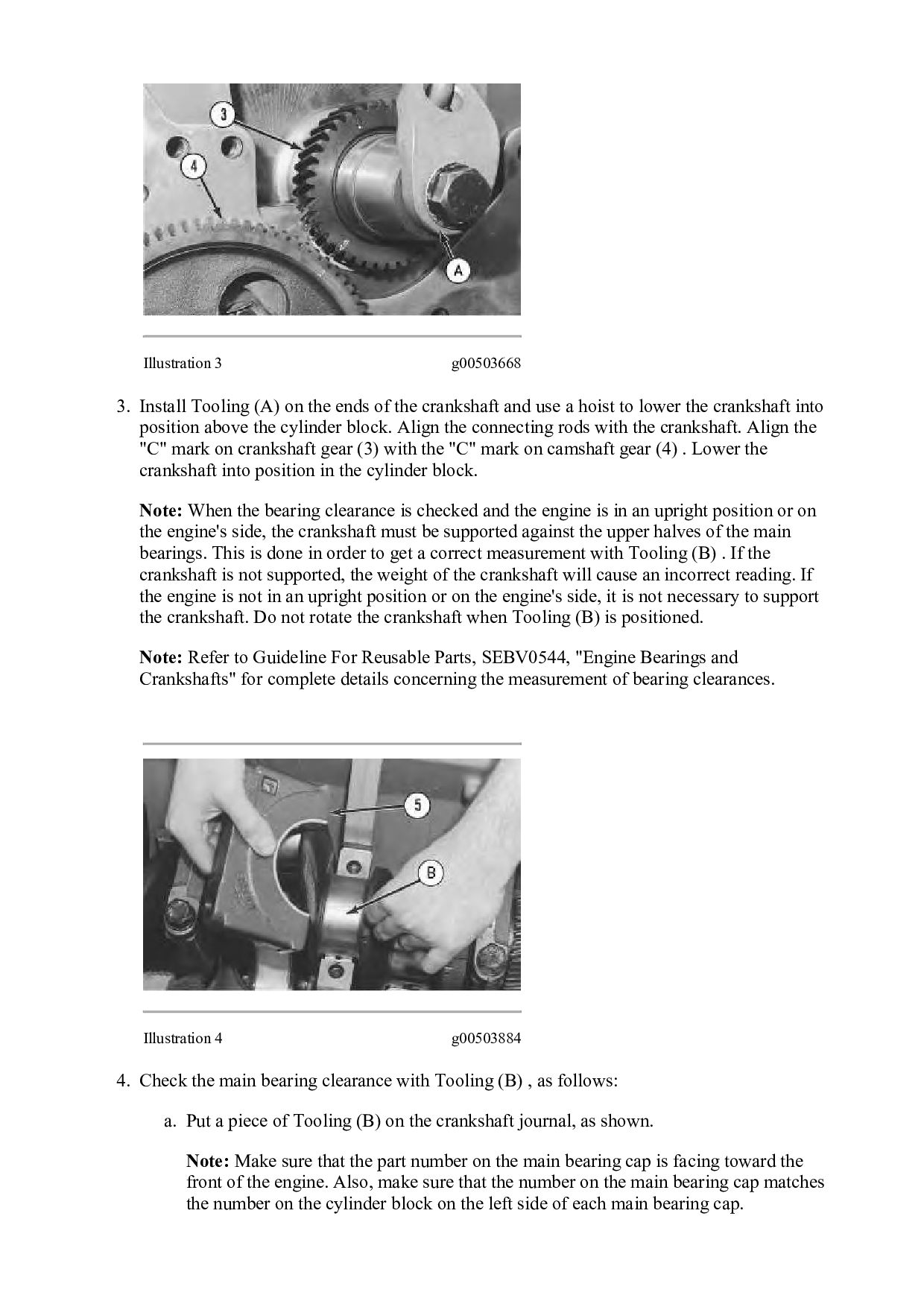
of the crankshaft and use a hoist to lower the crankshaft into position above the cylinder block. Align the connecting rods with the crankshaft. Align the "C" mark on crankshaft gear (3) with the "C" mark on camshaft gear (4) . Lower the crankshaft into position in the cylinder block. Note: When the bearing clearance is checked and the engine is in an upright position or on the engine's side, the crankshaft must be supported against the upper halves of the main bearings. This is done in order to get a correct measurement with Tooling (B) . If the crankshaft is not supported, the weight of the crankshaft will cause an incorrect reading. If the engine is not in an upright position or on the engine's side, it is not necessary to support the crankshaft. Do not rotate the crankshaft when Tooling (B) is positioned. Note: Refer to Guideline For Reusable Parts, SEBV0544, "Engine Bearings and Crankshafts" for complete details concerning the measurement of bearing clearances. Illustration 4 g00503884 4. Check the main bearing clearance with Tooling (B) , as follows: a. Put a piece of Tooling (B) on the crankshaft journal, as shown. Note: Make sure that the part number on the main bearing cap is facing toward the front of the engine. Also, make sure that the number on the main bearing cap matches the number on the cylinder block on the left side of each main bearing cap.
![Please write to us. Our email: [email protected] Please go to](https://files.speakerdeck.com/presentations/fa8992ab01ec4dcab222bb1968739abe/slide_28.jpg)