Upgrade to Pro — share decks privately, control downloads, hide ads and more …

Caterpillar_Cat_D6N_TRACK-TYPE_TRACTOR__Prefix_...

dcrfqdcnvk
May 21, 2024
5

 Caterpillar_Cat_D6N_TRACK-TYPE_TRACTOR__Prefix_P5W__Service_Repair_Manual__P5W00001_and_up_.pdf

dcrfqdcnvk

May 21, 2024
Tweet

More Decks by dcrfqdcnvk

Transcript

  1. Shutdown SIS Previous Screen Product: TRACK-TYPE TRACTOR Model: D6N TRACK-TYPE

    TRACTOR P5W Configuration: D6N LGP VPAT Track-Type Tractor P5W00001-UP (MACHINE) POWERED BY C7.1 Engine Disassembly and Assembly D5R and D6N Track-Type Tractor Power Train Media Number -M0071174-02 Publication Date -01/09/2015 Date Updated -25/07/2018 i06740784 Final Drive, Steering Planetary, and Brake (Right Side) - Remove and Install SMCS - 4050-010-RI; 4132-010-RI Removal Procedure Table 1 Required Tools Tool Part Number Part Description Qty A 142-1664 Lifting Bracket Gp 1 Start By: a. Separate the track. b. Remove the axle. Illustration 1 g06100971
  2. 1. Remove bolt (1), bolt (2), and the nuts. Illustration

    2 g01237341 2. Attach Tooling (A) and a suitable lifting device to final drive, steering planetary, and brake (right side) (3). The weight of final drive, steering planetary, and brake (right side) (3) is approximately 590 kg (1300 lb). Illustration 3 g01237361 3. Remove bolts (4). Note: Do not remove bolts (5). 4. Remove bolts (6).
  3. Illustration 4 g01237373 5. Remove final drive, steering planetary, and

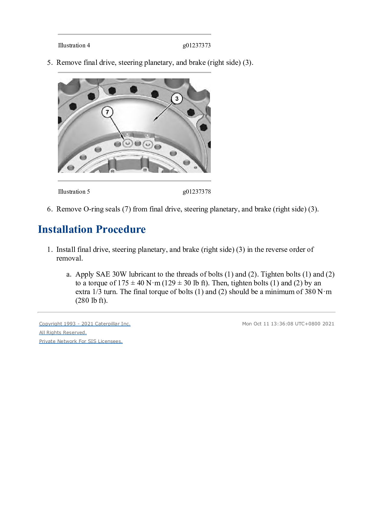
    brake (right side) (3). Illustration 5 g01237378 6. Remove O-ring seals (7) from final drive, steering planetary, and brake (right side) (3). Installation Procedure 1. Install final drive, steering planetary, and brake (right side) (3) in the reverse order of removal. a. Apply SAE 30W lubricant to the threads of bolts (1) and (2). Tighten bolts (1) and (2) to a torque of 175 ± 40 N·m (129 ± 30 lb ft). Then, tighten bolts (1) and (2) by an extra 1/3 turn. The final torque of bolts (1) and (2) should be a minimum of 380 N·m (280 lb ft). Copyright 1993 - 2021 Caterpillar Inc. All Rights Reserved. Private Network For SIS Licensees. Mon Oct 11 13:36:08 UTC+0800 2021
  4. Shutdown SIS Previous Screen Product: TRACK-TYPE TRACTOR Model: D6N TRACK-TYPE

    TRACTOR P5W Configuration: D6N LGP VPAT Track-Type Tractor P5W00001-UP (MACHINE) POWERED BY C7.1 Engine Disassembly and Assembly D5R and D6N Track-Type Tractor Power Train Media Number -M0071174-02 Publication Date -01/09/2015 Date Updated -25/07/2018 i06691884 Steering Planetary and Brake - Disassemble SMCS - 4132-015 Disassembly Procedure Table 1 Required Tools Tool Part Number Part Description Qty A 439-3940 Bracket As 3 B 1P-0520 Driver Group 1 C - 3/8 × 16 Forcing Screw 3 Start By: a. Remove the final drive, steering planetary, and brake (right side). Illustration 1 g01234433
  5. https://www.aservicemanualpdf.com/ My Dear Friend! Thank you very much for visiting.

    Full manual if required, please enter the following URL into your browser. https://www.aservicemanualpdf.com/
  6. 1. Position the final drive, steering planetary, and brake (right

    side). 2. Remove bolts (1A) (not shown) that hold steering planetary and brake (1) to final drive (2). 3. Attach Tooling (A) and a suitable lifting device (not shown) to steering planetary and brake (1). The weight of steering planetary and brake (1) is approximately 136 kg (300 lb). 4. Install Tooling (C) in the final drive hub. 5. Tighten Tooling (C) evenly to separate steering planetary and brake (1) from final drive (2). Illustration 2 g00622109 Personal injury can result from parts and/or covers under spring pressure. Spring force will be released when covers are removed. Be prepared to hold spring loaded covers as the bolts are loosened. 6. Remove bolts (3). 7. Remove ring gear (4) from housing (5).
  7. Illustration 3 g06078032 8. Remove friction discs (6) and brake

    plates (7) (not shown) from housing (5). Illustration 4 g06078040 Illustration 5 g06078046 9. Remove bolts (8) and plate (9). Note: Do not allow planetary carrier (11) to fall when the planetary carrier is pressed from housing (5). 10. Use a suitable press and Tooling (B) to remove planetary carrier (11) from housing (5).
  8. 11. Remove bearing cone (10) from housing (5). Illustration 6

    g00622127 12. Remove ring (14) from planetary carrier (11). 13. Remove bolts (13). 14. Remove slinger (12) from planetary carrier (11). NOTICE The component is destroyed if the component is removed. 15. If necessary, remove bearing cone (15) from planetary carrier (11). Illustration 7 g00996861 16. Use a hammer and a suitable punch to push spring pin (21) in planetary shaft (20).
  9. Illustration 8 g00996857 17. Remove planetary shaft (20), planetary gear

    (19), thrust discs (17), and roller bearings (18) from planetary carrier (11). 18. Remove spring pin (21) from planetary shaft (20). 19. Repeat Steps 16 through 18 for the remaining planetary gears. 20. Remove sun gear (16) from planetary carrier (11). Illustration 9 g00622132 Personal injury can result from parts and/or covers under spring pressure. Spring force will be released when covers are removed. Be prepared to hold spring loaded covers as the bolts are loosened. 21. Remove bolts (22) and the washers.
  10. 22. Remove retainer (23) from piston (24). Illustration 10 g00996858

    23. If necessary, remove bearing cups (25) from retainer (23). 24. Remove seal ring (26) from retainer (23). Illustration 11 g00622156 25. Remove piston (24) and O-ring seal (27) from the housing. Illustration 12 g00996860
  11. 26. Remove seal ring (28) from piston (24). Illustration 13

    g00819345 27. Remove disc spring (29) and ring (30) from housing (5). Copyright 1993 - 2021 Caterpillar Inc. All Rights Reserved. Private Network For SIS Licensees. Mon Oct 11 13:37:04 UTC+0800 2021
  12. Shutdown SIS Previous Screen Product: TRACK-TYPE TRACTOR Model: D6N TRACK-TYPE

    TRACTOR P5W Configuration: D6N LGP VPAT Track-Type Tractor P5W00001-UP (MACHINE) POWERED BY C7.1 Engine Disassembly and Assembly D5R and D6N Track-Type Tractor Power Train Media Number -M0071174-02 Publication Date -01/09/2015 Date Updated -25/07/2018 i06691986 Steering Planetary and Brake - Assemble SMCS - 4132-016 Assembly Procedure Table 1 Required Tools Tool Part Number Part Description Qty A 439-3940 Bracket As 3 D - Loctite 518 - Illustration 1 g00819345 Note: Orient the disc spring with the outer edge downward. 1. Install ring (30) and disc spring (29) in housing (5).
  13. Illustration 2 g00622157 2. Apply clean oil to seal ring

    (28). Note: Orient the seal ring with the lip downward. Refer to Illustration 2. 3. Install seal ring (28) in piston (24). Illustration 3 g00622156 4. Install piston (24) and O-ring seal (27) in the housing. Illustration 4 g00996858
  14. 5. If necessary, lower the temperature of bearing cups (25)

    and install bearing cups (25) in retainer (23). Note: Orient the seal ring with the lip downward. Refer to Illustration 4. 6. Apply clean oil to seal ring (26). Install seal ring (26) in retainer (23). Illustration 5 g00622132 7. Install retainer (23) on piston (24). Align the oil passage in retainer (23) with the oil passage and the O-ring seal in the housing. Install bolts (22). Illustration 6 g00996857 8. Install sun gear (16) in planetary carrier (11). 9. Install bearings (18) in planetary gear (19). 10. Install thrust discs (17) and planetary gear (19) in planetary carrier (11). Install planetary shaft (20).
  15. Illustration 7 g00996861 Note: If the rubber in spring pin

    (21) is damaged, replace spring pin (21). 11. Align the hole in planetary shaft (20) with the hole in planetary carrier (11) and install spring pin (21). Install spring pin (21) until the spring pin is even with the surface of planetary carrier (11). 12. Repeat Steps 9 through 11 for the remaining planetary gears. Illustration 8 g00622127 Note: If bearing cone (15) was removed from planetary carrier (11), a new bearing cone must be installed. 13. Raise the temperature of bearing cone (15). Install bearing cone (15) on planetary carrier (11). 14. Apply Tooling (D) to the flange of slinger (12). 15. Install slinger (12) on planetary carrier (11). Install bolts (13). 16. Install ring (14) in planetary carrier (11).
  16. Illustration 9 g06078188 17. Position housing (5) on planetary carrier

    (11). 18. Raise the temperature of bearing cone (10). Install bearing cone (10) on planetary carrier (11). Illustration 10 g06078197 19. Position plate (9) on the planetary carrier. 20. Install bolts (8). Illustration 11 g06078201
  17. 21. Install friction discs (6) and brake plates (7) (not

    shown). Alternate the friction discs and the brake plates. Illustration 12 g00622109 22. Position ring gear (4) on housing (5). 23. Install bolts (3). Tighten bolts (3) to a torque of 135 ± 20 N·m (100 ± 15 lb ft). Illustration 13 g01234433 24. Attach Tooling (A) and a suitable lifting device (not shown) to position the steering planetary and brake (1) on final drive (2). The weight of steering planetary and brake (1) is approximately 135 kg (300 lb). 25. Install bolts (1A) (not shown) that hold steering planetary and brake (1) on the final drive. End By: a. Install the final drive, steering planetary, and brake (right side). Copyright 1993 - 2021 Caterpillar Inc. All Rights Reserved. Private Network For SIS Licensees. Mon Oct 11 13:38:00 UTC+0800 2021
  18. Shutdown SIS Previous Screen Product: TRACK-TYPE TRACTOR Model: D6N TRACK-TYPE

    TRACTOR P5W Configuration: D6N LGP VPAT Track-Type Tractor P5W00001-UP (MACHINE) POWERED BY C7.1 Engine Disassembly and Assembly D5R and D6N Track-Type Tractor Power Train Media Number -M0071174-02 Publication Date -01/09/2015 Date Updated -25/07/2018 i06740854 Final Drive - Remove and Install SMCS - 4050-010 Removal Procedure Table 1 Required Tools Tool Part Number Part Description Qty A 142-1664 Lifting Bracket Gp 1 Start By: a. Separate the track. b. Remove the axle. 1. Drain the final drive oil. Refer to Operation and Maintenance Manual, "Final Drive Oil - Change" for the correct draining and filling procedures. Illustration 1 g06100971
  19. 2. Remove bolt (1), bolt (2), and the nuts. Illustration

    2 g01237341 Illustration 3 g01237514 3. Attach Tooling (A) and a suitable lifting device to final drive (3). The weight of final drive (3) is approximately 408 kg (900 lb). 4. Remove bolts (4) and bolts (5). Note: Do not remove bolts (6). 5. Remove final drive (3). Installation Procedure 1. Install final drive (3) in the reverse order of removal. a. Apply SAE 30W lubricant to the threads of bolts (1) and (2). Tighten bolts (1) and (2) to a torque of 175 ± 40 N·m (129 ± 30 lb ft). Then, tighten bolts (1) and (2) by an extra 1/3 turn. The final torque of bolts (1) and (2) should be a minimum of 380 N·m (280 lb ft). Copyright 1993 - 2021 Caterpillar Inc. All Rights Reserved. Mon Oct 11 13:38:56 UTC+0800 2021
  20. Shutdown SIS Previous Screen Product: TRACK-TYPE TRACTOR Model: D6N TRACK-TYPE

    TRACTOR P5W Configuration: D6N LGP VPAT Track-Type Tractor P5W00001-UP (MACHINE) POWERED BY C7.1 Engine Disassembly and Assembly D5R and D6N Track-Type Tractor Power Train Media Number -M0071174-02 Publication Date -01/09/2015 Date Updated -25/07/2018 i06691352 Final Drive - Disassemble SMCS - 4050-015 Disassembly Procedure Table 1 Required Tools Tool Part Number Part Description Qty A 439-3938 Link Bracket 3 B 1P-0074 Slide Hammer Puller Gp 1 C FT-1934 Puller Beam 1 - (16 mm x 190.5 mm) Bolt 4 5P-8247 Hard Washer 4 6V-3170 Double Acting Cylinder 1 9U-6600 Hand Hydraulic Pump 1 1P-0521 Driver Group 1 D 439-3940 Bracket As 2 Start By: a. Remove the final drive.
  21. Illustration 1 g01234745 1. Attach Tooling (A) and a suitable

    lifting device to carrier (1). The weight of carrier (1) is approximately 50 kg (110 lb). 2. Remove bolts (2) and carrier (1) from sprocket hub (3). Position carrier (1) onto suitable cribbing. Illustration 2 g01234760 3. Remove bolt (4), the washer, the retainer, and the O-ring seal from carrier (1). 4. Use a suitable press to remove shaft (5) from carrier (1). 5. Repeat Steps 3 and 4 for the remaining shafts.
  22. Illustration 3 g06077476 6. Remove planetary gear (8) from carrier

    (1). 7. Remove bearing cones (6) and (9) from planetary gear (8). 8. Remove bearing cups (7) from planetary gear (8). 9. Repeat Steps 6 through 8 for the remaining planetary gears.
  23. Illustration 4 g00988981 10. Remove bolts (10) and retainer (11).

    11. Remove ring gear hub (12) and ring gear (13). Illustration 5 g00988984 12. Remove ring (14) and ring gear hub (12) from ring gear (13). Illustration 6 g00988985 13. Use Tooling (B) to remove bushing (15) and lip-type seal (16) (not shown).
  24. Illustration 7 g00988979 14. Raise the temperature of bearing cone

    (17). 15. Use Tooling (C) to remove bearing cone (17) from the spindle. Note: Do not lift the sprocket hub so that the sprocket hub contacts the fittings that are on the hydraulic cylinder. Damage to the fittings could occur. 16. Remove Tooling (C). Illustration 8 g01235181 17. Attach Tooling (D) and a suitable lifting device to sprocket hub (3). The weight of sprocket hub (3) is approximately 135 kg (298 lb). Remove sprocket hub (3) from the spindle.
  25. Illustration 9 g01235238 18. Remove bearing cups (18) and (19)

    from sprocket hub (3). 19. Remove Duo-cone seal (20) from sprocket hub (3). Illustration 10 g01235241 20. Remove Duo-cone seal (22) from spindle (23). 21. Remove bearing cone (21) from spindle (23). Copyright 1993 - 2021 Caterpillar Inc. All Rights Reserved. Private Network For SIS Licensees. Mon Oct 11 13:39:52 UTC+0800 2021
  26. Shutdown SIS Previous Screen Product: TRACK-TYPE TRACTOR Model: D6N TRACK-TYPE

    TRACTOR P5W Configuration: D6N LGP VPAT Track-Type Tractor P5W00001-UP (MACHINE) POWERED BY C7.1 Engine Disassembly and Assembly D5R and D6N Track-Type Tractor Power Train Media Number -M0071174-02 Publication Date -01/09/2015 Date Updated -25/07/2018 i06691406 Final Drive - Assemble SMCS - 4050-016 Assembly Procedure Table 1 Required Tools Tool Part Number Part Description Qty A 439-3938 Link Bracket 3 D 439-3940 Bracket As 2 E 1P-0520 Driver Gp 1 F 1U-6437 Duo-Cone Seal Installer As 1 G 1U-7234 Feeler Gauge 1
  27. Illustration 1 g01235241 1. Raise the temperature of bearing cone

    (21). Lubricate bearing cone (21) with the lubricant that is being sealed. Install bearing cone (21) onto spindle (23). 2. Use Tooling (F) (not shown) to install Duo-cone seal (22). Refer to Disassembly and Assembly, "Duo-Cone Conventional Seals - Install". Illustration 2 g01235238 3. Lower the temperature of bearing cups (19) and (18). 4. Install bearing cups (19) and (18) in sprocket hub (3). 5. Use Tooling (F) (not shown) to install Duo-cone seal (20) in sprocket hub (3). Refer to Disassembly and Assembly, "Duo-Cone Conventional Seals - Install".
  28. Illustration 3 g01235181 6. Attach Tooling (D) and a suitable

    lifting device to sprocket hub (3). The weight of sprocket hub (3) is approximately 135 kg (298 lb). Install sprocket hub (3) onto the spindle. Illustration 4 g00990323 7. Lubricate lip-type seal (16) with the lubricant that is being sealed. Use Tooling (E) to install lip-type seal (16) and bushing (15).
  29. Thank you very much for your reading. Please Click Here.

    Then Get COMPLETE MANUAL. NO WAITING NOTE: If there is no response to click on the link above, please download the PDF document first and then click on it.
  30. Illustration 6 g02145273 9. Raise the temperature of bearing cone

    (17). Lubricate bearing cone (17) with the lubricant that is being sealed. Install bearing cone (17) on the spindle. 10. Install ring gear hub (12) and ring gear (13) as an assembly. 11. Install retainer (11) and bolts (10). Tighten all bolts (10) in a star pattern. Tighten bolts (10) to a torque of 120 ± 20 N·m (89 ± 15 lb ft). Continually rotate hub (12) to properly seat bearing cone (17). Tighten bolts (10) to a torque of 120 ± 20 N·m (89 ± 15 lb ft) to ensure the proper torque. 12. Use Tooling (G) (not shown) to verify from inside the axle opening that the spindle is touching the retainer. 13. If necessary, repeat Step 11 and Step 12 to verify that bearing cone (17) is seated properly.
  31. Illustration 7 g06077476 14. Lower the temperature of bearing cups

    (7). Install bearing cups (7) into planetary gear (8). 15. Lubricate bearing cones (6) and (9) with the lubricant that is being sealed. Position bearing cones (6) and (9) into planetary gear (8). 16. Position planetary gear (8) into carrier (1). 17. Repeat Steps 14 through 16 for the remaining planetary gears. Illustration 8 g01235164 18. Lower the temperature of shaft (5). Use a suitable press to install shaft (5). Install shaft (5) until the end of the shaft is flush with the outer surface of carrier (1).
  32. https://www.aservicemanualpdf.com/ My Dear Friend! Thank you very much for visiting.

    Full manual if required, please enter the following URL into your browser. https://www.aservicemanualpdf.com/