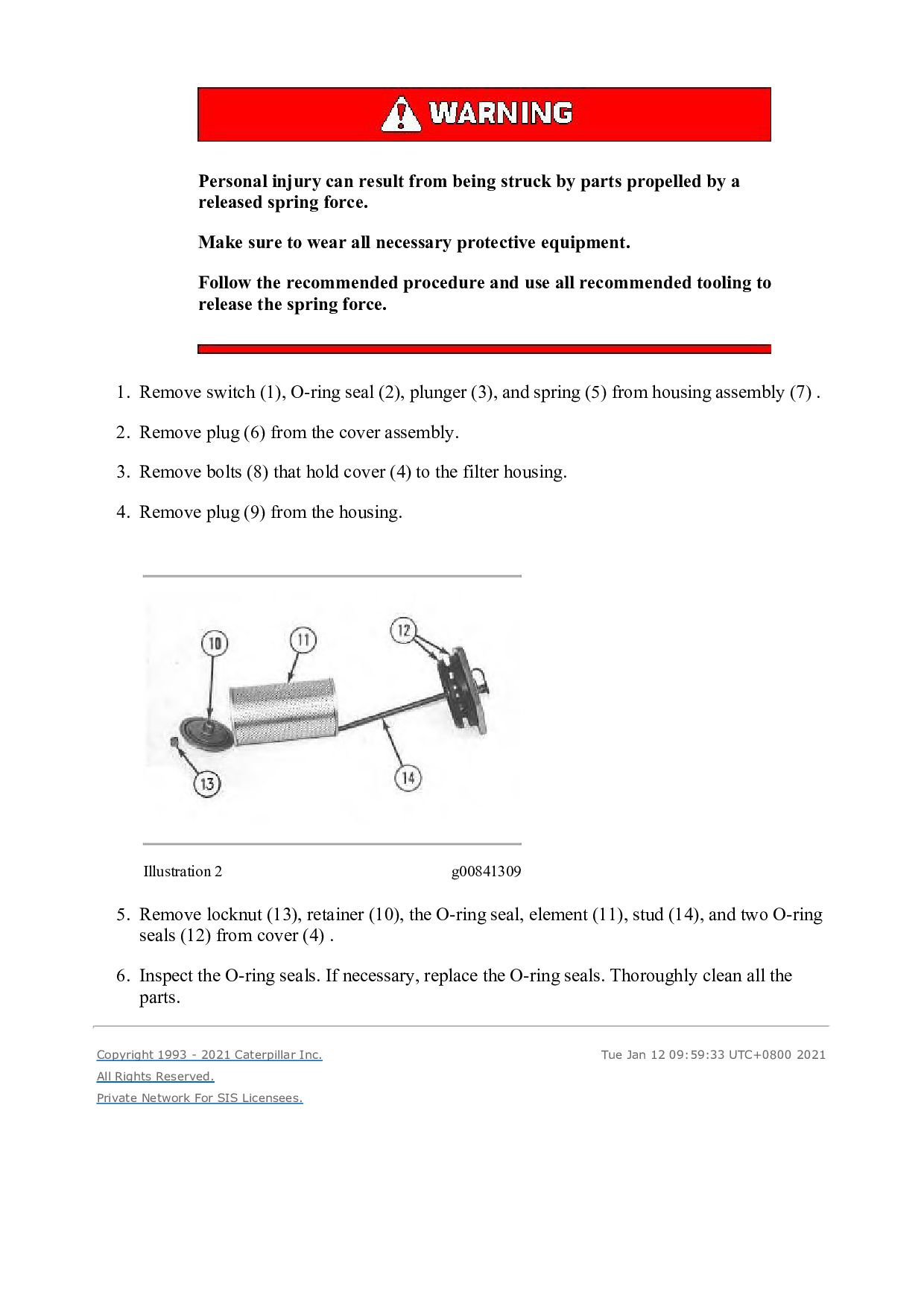
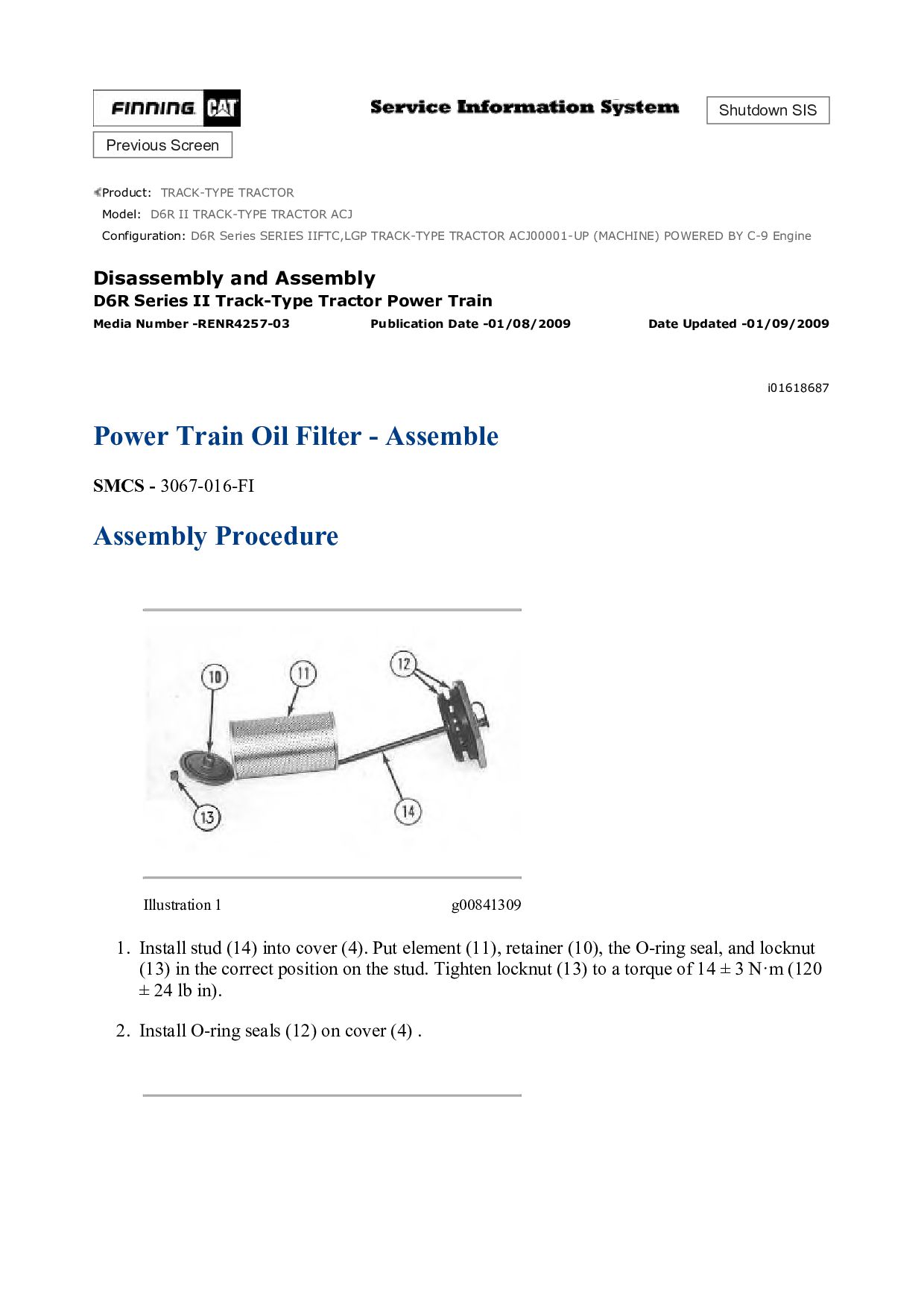
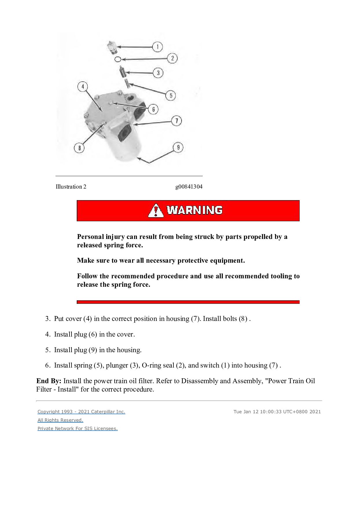
by a released spring force. Make sure to wear all necessary protective equipment. Follow the recommended procedure and use all recommended tooling to release the spring force. 1. Remove switch (1), O-ring seal (2), plunger (3), and spring (5) from housing assembly (7) . 2. Remove plug (6) from the cover assembly. 3. Remove bolts (8) that hold cover (4) to the filter housing. 4. Remove plug (9) from the housing. Illustration 2 g00841309 5. Remove locknut (13), retainer (10), the O-ring seal, element (11), stud (14), and two O-ring seals (12) from cover (4) . 6. Inspect the O-ring seals. If necessary, replace the O-ring seals. Thoroughly clean all the parts. Copyright 1993 - 2021 Caterpillar Inc. All Rights Reserved. Private Network For SIS Licensees. Tue Jan 12 09:59:33 UTC+0800 2021