Upgrade to Pro — share decks privately, control downloads, hide ads and more …

Caterpillar_Cat_980F_WHEEL_LOADER__Prefix_5XJ__Service_Repair_Manual__5XJ00713_and_up_.pdf

dcfv
May 20, 2024
4

 Caterpillar_Cat_980F_WHEEL_LOADER__Prefix_5XJ__Service_Repair_Manual__5XJ00713_and_up_.pdf

dcfv

May 20, 2024
Tweet

More Decks by dcfv

Transcript

  1. Shutdown SIS Previous Screen Product: WHEEL LOADER Model: 980F WHEEL

    LOADER 5XJ Configuration: 980F SERIES II WHEEL LOADER 5XJ00713-UP (MACHINE) POWERED BY 3406 ENGINE Disassembly and Assembly 3406C DIESEL ENGINES FOR CATERPILLAR BUILT MACHINES Media Number -SENR6409-02 Publication Date -01/07/2006 Date Updated -19/05/2015 SENR64090026 Cylinder Head Assembly SMCS - 1100-011; 1100-012 Remove Cylinder Head Assembly Start By: a. remove rocker shaft assemblies and push rods b. remove water temperature regulator c. remove aftercooler housing d. remove fuel injection lines e. remove exhaust manifold Typical Example 1. Remove bolts (1) from the alternator bracket. 2. Remove the bolts that hold plate (3) and remove the plate. 3. Disconnect water line (2) from the air compressor. NOTE: Turn the water line tee toward the lifting bracket in order to provide clearance to remove the head bolt.
  2. 4. Remove bolts (4) and (5) that hold the cylinder

    head assembly to the cylinder block. 5. Fasten a hoist and remove the cylinder head assembly. The weight is approximately 135 kg (300 lb). NOTICE Do not put the cylinder head assembly down on a flat surface. This can cause damage to the fuel injection valves. 6. Remove the gasket and seals from the spacer plate. Install Cylinder Head Assembly NOTE: Be sure a new gasket has been installed between the spacer plate and the cylinder block. See topic, "Remove & Install Spacer Plate". 1. Thoroughly clean the spacer plate and the bottom surface of the cylinder head assembly. Install a new head gasket, new seals (1) and two O-ring seals (2). 2. Fasten a hoist and put the cylinder head assembly (3) in position on the cylinder block. 3. Tighten the bolts in sequence shown in Illustration D11970.
  3. (1) Large bolts (3/4 inch). Put 6V4876 Molycoat Paste Lubricant

    on bolt threads and between washers and underside of bolt heads. (2) Small bolts (3/8 inch). See Step 4h. 4. Install the cylinder head bolts and washers. Tighten the bolts in sequence shown. a. Tighten bolts 1 through 14 in number sequence to 270 ± 25 N·m (200 ± 20 lb ft). b. Tighten bolts 1 through 14 in number sequence to 470 ± 20 N·m (345 ± 15 lb ft). c. Tighten bolts 1 through 14 in number sequence again to 470 ± 20 N·m (345 ± 15 lb ft). d. Install the rocker arm shafts for the engine valves and the remaining (3/4 in) bolts and/or compression brake studs. e. Tighten bolts 15 through 26 in number sequence to 270 ± 25 N·m (200 ± 20 lb ft). f. Tighten bolts 15 through 26 in number sequence to 450 ± 20 N·m (330 ± 15 lb ft). g. Tighten bolts 15 through 26 in number sequence again to 450 ± 20 N·m (330 ± 15 lb ft). h. Tighten the thirteen small bolts (2) to 45 ± 7 N·m (33 ± 5 lb ft). 5. Make an adjustment to the valves to have a clearance of 0.38 mm (.015 in) for intake and 0.76 mm (.030 in) for exhaust. Tighten the locknuts for the valve adjustment screws to a torque of 28 ± 4 N·m (21 ± 3 lb ft). 6. Install the valve cover bases and the inner fuel lines. See topic, "Install Rocker Shaft Assemblies & Push Rods". 7. Install the valve covers. See topic, "Install Valve Covers". Typical Example 8. Install plate (4).
  4. 9. Connect the water line to the air compressor. 10.

    Install bolts (5) for the alternator bracket. End By: a. install exhaust manifold b. install fuel injection lines c. install aftercooler housing d. install water temperature regulator e. install rocker shaft assemblies and push rods Copyright 1993 - 2022 Caterpillar Inc. All Rights Reserved. Private Network For SIS Licensees. Mon Feb 21 19:45:18 UTC+0800 2022
  5. Shutdown SIS Previous Screen Product: WHEEL LOADER Model: 980F WHEEL

    LOADER 5XJ Configuration: 980F SERIES II WHEEL LOADER 5XJ00713-UP (MACHINE) POWERED BY 3406 ENGINE Disassembly and Assembly 3406C DIESEL ENGINES FOR CATERPILLAR BUILT MACHINES Media Number -SENR6409-02 Publication Date -01/07/2006 Date Updated -19/05/2015 SENR64090027 Spacer Plate SMCS - 1221-011; 1221-012 Remove Spacer Plate Start By: a. remove cylinder head assembly 1. Remove spacer plate (1) from the cylinder block. NOTICE Do not cause damage to the dowels. 2. Remove the spacer plate gasket and two O-ring seals. Install Spacer Plate
  6. https://www.aservicemanualpdf.com/ My Dear Friend! Thank you very much for visiting.

    Full manual if required, please enter the following URL into your browser. https://www.aservicemanualpdf.com/
  7. 1. Thoroughly clean the spacer plate and cylinder block surface.

    Install two O-ring seals (1) in the cylinder block. NOTICE Both surfaces of the spacer plate, top of cylinder block and both sides of the spacer plate gasket must be clean and dry. Gasket adhesives or other substances must not be used on these surfaces. 2. Install a new gasket between the spacer plate and cylinder block. Put spacer plate (2) in position on the cylinder block. 3. Check cylinder liner projection. See topic, "Install Cylinder Liners". End By: a. install cylinder head assembly Copyright 1993 - 2022 Caterpillar Inc. All Rights Reserved. Private Network For SIS Licensees. Mon Feb 21 19:46:13 UTC+0800 2022
  8. Shutdown SIS Previous Screen Product: WHEEL LOADER Model: 980F WHEEL

    LOADER 5XJ Configuration: 980F SERIES II WHEEL LOADER 5XJ00713-UP (MACHINE) POWERED BY 3406 ENGINE Disassembly and Assembly 3406C DIESEL ENGINES FOR CATERPILLAR BUILT MACHINES Media Number -SENR6409-02 Publication Date -01/07/2006 Date Updated -19/05/2015 SENR64090028 Valves SMCS - 1105-011; 1105-012 Remove Valves Start By: a. remove cylinder head assembly 1. Use Tool (A) to compress springs (1). 2. Remove the locks. 3. Remove Tool (A), the valve, the rotocoil, and the spring. NOTE: If a valve can be used again, put identification on the valve for location at installation.
  9. 4. Use Tool (B) to check spring force. The specifications

    for the spring are given in Specifications Manual, SENR6470. 5. Do Steps 1 through 4 again for the remainder of the valves. Install Valves 1. Put clean engine oil on the valve stem. Install washer (3), spring (2), rotocoil (1) and the valve. 2. Use Tool (A) to compress the spring. 3. Install locks (4) with the thick end up. Locks can be thrown from valve when compressor is released, if they are not in their correct position on the valve stem.
  10. 4. Remove the compressor and hit the valve with a

    soft faced hammer to be sure locks are in their correct position on the valve. 5. Do Steps 1 through 4 again for the remainder of the valves. End By: a. install cylinder assembly Copyright 1993 - 2022 Caterpillar Inc. All Rights Reserved. Private Network For SIS Licensees. Mon Feb 21 19:47:09 UTC+0800 2022
  11. Shutdown SIS Previous Screen Product: WHEEL LOADER Model: 980F WHEEL

    LOADER 5XJ Configuration: 980F SERIES II WHEEL LOADER 5XJ00713-UP (MACHINE) POWERED BY 3406 ENGINE Disassembly and Assembly 3406C DIESEL ENGINES FOR CATERPILLAR BUILT MACHINES Media Number -SENR6409-02 Publication Date -01/07/2006 Date Updated -19/05/2015 SENR64090029 Valve Seat Inserts SMCS - 1103-010 Remove & Install Valve Seat Inserts Start By: a. remove valves 1. Use Tool (A) to remove the valve seat inserts from the cylinder head. 2. Clean and remove any burrs from the valve seat bores. NOTE: For reconditioning information of the cylinder head, see Service Training Meeting Guide, SESV1202. NOTE: The following steps are for the installation of the valve seat inserts.
  12. 3. Lower the temperature of the new valve seat inserts.

    Use Tool (B) to install the new valve seat inserts in the cylinder head. End By: a. install valves Copyright 1993 - 2022 Caterpillar Inc. All Rights Reserved. Private Network For SIS Licensees. Mon Feb 21 19:48:05 UTC+0800 2022
  13. Shutdown SIS Previous Screen Product: WHEEL LOADER Model: 980F WHEEL

    LOADER 5XJ Configuration: 980F SERIES II WHEEL LOADER 5XJ00713-UP (MACHINE) POWERED BY 3406 ENGINE Disassembly and Assembly 3406C DIESEL ENGINES FOR CATERPILLAR BUILT MACHINES Media Number -SENR6409-02 Publication Date -01/07/2006 Date Updated -19/05/2015 SENR64090030 Bridge Dowels SMCS - 1121-011; 1121-012 Remove Bridge Dowels Start By: a. remove valves 1. Use Tool (A) to remove bridge dowel (1). Install Bridge Dowels
  14. 1. Use Tool (A) to install the bridge dowel. End

    By: a. install valves Copyright 1993 - 2022 Caterpillar Inc. All Rights Reserved. Private Network For SIS Licensees. Mon Feb 21 19:49:01 UTC+0800 2022
  15. Shutdown SIS Previous Screen Product: WHEEL LOADER Model: 980F WHEEL

    LOADER 5XJ Configuration: 980F SERIES II WHEEL LOADER 5XJ00713-UP (MACHINE) POWERED BY 3406 ENGINE Disassembly and Assembly 3406C DIESEL ENGINES FOR CATERPILLAR BUILT MACHINES Media Number -SENR6409-02 Publication Date -01/07/2006 Date Updated -19/05/2015 SENR64090031 Valve Guides SMCS - 1104-012; 1104-011 Remove Valve Guides Start By: a. remove valves 1. Use Tool (A) to remove the valve guides. Install Valve Guides
  16. 1. Put clean engine oil on the outside of the

    valve guide. 2. Use Tool (A) to install the valve guides. 3. After installation, the inside diameter of the valve guide must be 9.487 ± 0.025 mm (.3735 ± .0010 in). The maximum diameter of used guides is 8.538 mm (.3361 in). End By: a. install valves Copyright 1993 - 2022 Caterpillar Inc. All Rights Reserved. Private Network For SIS Licensees. Mon Feb 21 19:49:56 UTC+0800 2022
  17. Shutdown SIS Previous Screen Product: WHEEL LOADER Model: 980F WHEEL

    LOADER 5XJ Configuration: 980F SERIES II WHEEL LOADER 5XJ00713-UP (MACHINE) POWERED BY 3406 ENGINE Disassembly and Assembly 3406C DIESEL ENGINES FOR CATERPILLAR BUILT MACHINES Media Number -SENR6409-02 Publication Date -01/07/2006 Date Updated -19/05/2015 SENR64090032 Oil Pan & Plate SMCS - 1302-011; 1302-012 Remove Oil Pan & Plate Typical Example 1. Drain the oil from the engine into a suitable container for storage or disposal. 2. Remove the lower clamp and bracket that hold the breather tube to the cylinder block and oil pan. 3. Remove all but four of the bolts (1) that hold the oil pan to the cylinder block. Use two persons to hold the oil pan in position while the last four bolts are removed. 4. Remove the oil pan (2). Weight of the oil pan is 57 kg (126 lb).
  18. 5. Remove suction bell (3). Remove suction bell and tube

    (4). Remove oil supply tube (5). Remove plate (6). Install Oil Pan & Plate 1. Put plate (1) in position on the cylinder block. Put suction bell and tube (2) in position on the oil pump and cylinder block. Install the bolts that hold it. 2. Install oil supply tube (4). 3. Install the suction bell (3). 4. Install two 3/8 in 16 NC Guide Pins 6 in long in the cylinder block. Put the oil pan (5) in position on the cylinder block. Install all but two of the bolts that hold it. Remove the two guide pins. Install the last two bolts. 5. Fill the engine with oil to the correct level. See the Operation & Maintenance Manual. Copyright 1993 - 2022 Caterpillar Inc. All Rights Reserved. Private Network For SIS Licensees. Mon Feb 21 19:50:52 UTC+0800 2022
  19. Shutdown SIS Previous Screen Product: WHEEL LOADER Model: 980F WHEEL

    LOADER 5XJ Configuration: 980F SERIES II WHEEL LOADER 5XJ00713-UP (MACHINE) POWERED BY 3406 ENGINE Disassembly and Assembly 3406C DIESEL ENGINES FOR CATERPILLAR BUILT MACHINES Media Number -SENR6409-02 Publication Date -01/07/2006 Date Updated -19/05/2015 SENR64090033 Oil Pump SMCS - 1304-010; 1304-015; 1304-016 Remove & Install Oil Pump Start By: a. remove oil pan 1. Remove oil supply tube (1) and suction bell and tube (2). 2. Remove bolts (3) that hold the oil pump to the cylinder block and remove oil pump (4). 3. To install, put oil pump (4) in position on the cylinder block. Install the bolts that hold the oil pump to the cylinder block. 4. Put clean engine oil on the O-ring seals of the tubes.
  20. 5. Install oil supply tube (1), suction bell and tube

    (2). End By: a. install oil pan Disassemble Oil Pump Start By: a. remove oil pump 1. Remove the bolt and washer that hold the gear on the shaft. 2. Use Tool (A) and remove drive gear (1) from the shaft. Remove the key from the shaft. 3. Remove retainer (3) for the bypass valve. Remove the spring and the bypass valve. 4. Remove cover (2) from the pump body.
  21. 5. Use Tool (B) and remove the bearings from the

    cover. 6. Remove gears (5) from pump body (4). 7. Use Tool (B) and remove the bearings from pump body (4). Assemble Oil Pump 1. Use Tool (B) to install the bearings in the pump body. Install the bearings so the joint in the bearings is 30 ± 15 degrees from the center line of the oil pump outlet passage (2).
  22. 2. Install idler gear and drive gear (5) in the

    oil pump body (4). Put clean engine oil on the bearings and the gears. 3. Use Tool (A) and install the bearings in cover (2). Install the bearings so the joint of the bearing bores toward oil pump outlet passage (6). 4. Install bypass valve (7), spring (8) and the retainer. 5. Install the key on the shaft. 6. Install gear (1) on the shaft. Install the washer and bolt that hold the gear on the shaft. Be sure the pump turns freely after assembly. End By: a. install oil pump Copyright 1993 - 2022 Caterpillar Inc. All Rights Reserved. Private Network For SIS Licensees. Mon Feb 21 19:51:48 UTC+0800 2022
  23. Shutdown SIS Previous Screen Product: WHEEL LOADER Model: 980F WHEEL

    LOADER 5XJ Configuration: 980F SERIES II WHEEL LOADER 5XJ00713-UP (MACHINE) POWERED BY 3406 ENGINE Disassembly and Assembly 3406C DIESEL ENGINES FOR CATERPILLAR BUILT MACHINES Media Number -SENR6409-02 Publication Date -01/07/2006 Date Updated -19/05/2015 SENR64090034 Piston Cooling Tubes SMCS - 1307-010 Remove & Install Piston Cooling Tubes Start By: a. remove oil pump NOTE: The piston and connecting rod were removed for better illustration. 1. Remove bolts (1). Remove piston cooling tubes (2) from the engine. Use Tool (A) to turn the crankshaft in a clockwise direction (as seen from the front of the engine) to get access to all of the piston cooling tubes. NOTE: The following steps are for the installation of the piston cooling tubes. 2. Check the alignment of the piston cooling tubes with Tool (B). See Use Of 5P8709 Tool Group for Alignment Of Piston Cooling Jets, SMHS7267 for the correct alignment procedure.
  24. 3. Install piston cooling tubes (2) on the engine. Use

    Tool (A) to turn the crankshaft clockwise (as seen from the front of the engine) to get access for the installation of the piston cooling tubes. End By: a. install oil pump Copyright 1993 - 2022 Caterpillar Inc. All Rights Reserved. Private Network For SIS Licensees. Mon Feb 21 19:52:44 UTC+0800 2022
  25. Shutdown SIS Previous Screen Product: WHEEL LOADER Model: 980F WHEEL

    LOADER 5XJ Configuration: 980F SERIES II WHEEL LOADER 5XJ00713-UP (MACHINE) POWERED BY 3406 ENGINE Disassembly and Assembly 3406C DIESEL ENGINES FOR CATERPILLAR BUILT MACHINES Media Number -SENR6409-02 Publication Date -01/07/2006 Date Updated -19/05/2015 SENR64090035 Pistons & Connecting Rod Assemblies SMCS - 1225-011; 1225-012; 1225-017 Remove Pistons & Connecting Rod Assemblies Start By: a. remove cylinder head assembly b. remove oil pump c. remove piston cooling tubes 1. Remove the carbon ridge from the top inside surface of the cylinder liners. 2. Turn the crankshaft until two pistons are at bottom center. 3. Remove bolts (1) and the bearing caps. Push the rods and pistons up until the rings are out of the cylinder liners.
  26. 4. Remove pistons (2) and connecting rods from the cylinder

    liners. 5. Do Steps 1 through 4 for the remainder of the pistons and connecting rods. Install Pistons & Connecting Rod Assemblies 1. Put clean engine oil on piston rings, connecting rod bearings and cylinder liners. 2. Use Tool (A), and install piston (2) and the connecting rod in the cylinder liner. 3. Install the bearing cap on the connecting rod with the number on the side of the bearing cap on the same side and same number as on the connecting rod. 4. Put 2P2506 Thread Lubricant on the threads of the bolts. Install the nuts, and tighten them to a torque of 90 ± 8 N·m (67 ± 6 lb ft). Put a mark on the nuts and cap, and tighten the nuts an extra 90 ± 5 degrees. 5. Do Steps 1 through 4 for the remainder of the pistons and connecting rods. End By: a. install piston cooling tubes b. install oil pump c. install cylinder head assembly
  27. Disassemble & Assemble Pistons & Connecting Rod Assemblies Start By:

    a. remove pistons and connecting rod assemblies 1. Remove bearings (3) from the connecting rod and connecting rod cap. 2. Remove retainer ring (1) with Tool (A). 3. Remove pin (2) and connecting rod (4) from the piston. 4. Remove piston rings (5) from the piston with Tool (B). Clean the piston ring grooves on the pistons with an acceptable ring groove cleaning tool.
  28. NOTE: See, Use Of Piston Bearing Removal And Installation Tools,

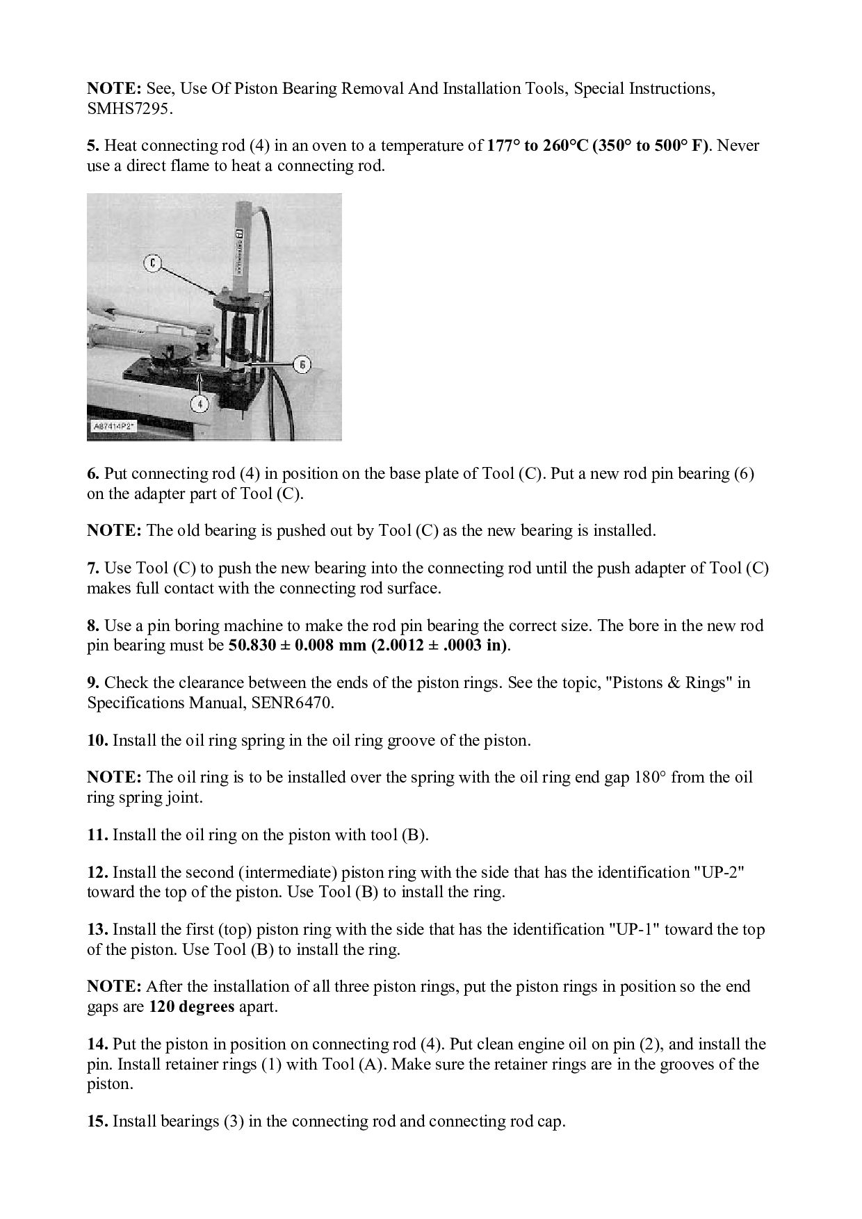
    Special Instructions, SMHS7295. 5. Heat connecting rod (4) in an oven to a temperature of 177° to 260°C (350° to 500° F). Never use a direct flame to heat a connecting rod. 6. Put connecting rod (4) in position on the base plate of Tool (C). Put a new rod pin bearing (6) on the adapter part of Tool (C). NOTE: The old bearing is pushed out by Tool (C) as the new bearing is installed. 7. Use Tool (C) to push the new bearing into the connecting rod until the push adapter of Tool (C) makes full contact with the connecting rod surface. 8. Use a pin boring machine to make the rod pin bearing the correct size. The bore in the new rod pin bearing must be 50.830 ± 0.008 mm (2.0012 ± .0003 in). 9. Check the clearance between the ends of the piston rings. See the topic, "Pistons & Rings" in Specifications Manual, SENR6470. 10. Install the oil ring spring in the oil ring groove of the piston. NOTE: The oil ring is to be installed over the spring with the oil ring end gap 180° from the oil ring spring joint. 11. Install the oil ring on the piston with tool (B). 12. Install the second (intermediate) piston ring with the side that has the identification "UP-2" toward the top of the piston. Use Tool (B) to install the ring. 13. Install the first (top) piston ring with the side that has the identification "UP-1" toward the top of the piston. Use Tool (B) to install the ring. NOTE: After the installation of all three piston rings, put the piston rings in position so the end gaps are 120 degrees apart. 14. Put the piston in position on connecting rod (4). Put clean engine oil on pin (2), and install the pin. Install retainer rings (1) with Tool (A). Make sure the retainer rings are in the grooves of the piston. 15. Install bearings (3) in the connecting rod and connecting rod cap.
  29. NOTE: Be sure the tabs in back of the bearings

    are in tab slots of the connecting rod and connecting rod cap. End By: a. install pistons and connecting rod assemblies Copyright 1993 - 2022 Caterpillar Inc. All Rights Reserved. Private Network For SIS Licensees. Mon Feb 21 19:53:39 UTC+0800 2022
  30. Shutdown SIS Previous Screen Product: WHEEL LOADER Model: 980F WHEEL

    LOADER 5XJ Configuration: 980F SERIES II WHEEL LOADER 5XJ00713-UP (MACHINE) POWERED BY 3406 ENGINE Disassembly and Assembly 3406C DIESEL ENGINES FOR CATERPILLAR BUILT MACHINES Media Number -SENR6409-02 Publication Date -01/07/2006 Date Updated -19/05/2015 SENR64090036 Cylinder Liners SMCS - 1216-010 Remove & Install Cylinder Liners Start By: a. remove pistons and connecting rod assemblies 1. Put covers on the journals of the crankshaft for protection from dirt or water. 2. Remove the cylinder liners with Tool (A) as shown. NOTE: The Caterpillar pack pulling tools can be used to remove the cylinder liner, piston and connecting rod as a unit. For more detail, see Special Instruction, SEHS8554.
  31. 3. To install, clean the cylinder liners and liner bores

    in the cylinder block. 4. Install cylinder liners (1) in the block without the O-ring seals or filler band. 5. To check the cylinder liner projection, see the topic, "Cylinder Liner Projection" in Systems Operations Testing & Adjusting Manual SENR6471. 6. Remove the liner. Install new O-ring seals on the liners. 7. Put liquid soap on the O-ring seals and on the cylinder bores. Put the filler band in SAE 30W Oil, then immediately install the filler band on the cylinder liner. Immediately install the cylinder liner in the cylinder block with Tool (B) before expansion of the band. End By: a. install pistons and connecting rod assemblies Copyright 1993 - 2022 Caterpillar Inc. All Rights Reserved. Private Network For SIS Licensees. Mon Feb 21 19:54:35 UTC+0800 2022
  32. Shutdown SIS Previous Screen Product: WHEEL LOADER Model: 980F WHEEL

    LOADER 5XJ Configuration: 980F SERIES II WHEEL LOADER 5XJ00713-UP (MACHINE) POWERED BY 3406 ENGINE Disassembly and Assembly 3406C DIESEL ENGINES FOR CATERPILLAR BUILT MACHINES Media Number -SENR6409-02 Publication Date -01/07/2006 Date Updated -19/05/2015 SENR64090037 Timing Gear Cover SMCS - 1166-010 Remove & Install Timing Gear Cover Start By: a. remove water pump b. remove governor and fuel pump drive c. remove oil pan d. remove crankshaft front seal and wear sleeve e. remove engine front support 1. Remove governor and fuel pump drive covers to timing gear cover bolts (1). 2. Remove two fuel injection pump housing to timing gear cover bolts (2) and two plates to cover bolts (3).
  33. 3. Remove the five timing gear covers to cylinder block

    bolts and remove timing gear cover (4). 4. To install, be sure that O-ring seal (5) is in position in the timing gear plate as shown. 5. Put a new gasket in position and install timing gear cover (4) over the two dowel pins in the cylinder block. 6. Install the bolts that hold the timing gear cover to the cylinder block. Cut the cover gasket to make it even with the surface of the cylinder block and the bottom of the timing gear cover. 7. Install the bolts that hold the governor and fuel pump drive cover to the timing gear cover. Install the fuel injection pump housing to timing gear cover bolts and the two plates to cover bolts. End By: a. install engine front support b. install crankshaft front seal and wear sleeve c. install oil pan d. install governor and fuel pump drive e. install water pump Copyright 1993 - 2022 Caterpillar Inc. All Rights Reserved. Private Network For SIS Licensees. Mon Feb 21 19:55:31 UTC+0800 2022
  34. Please write to us. Our email: [email protected] Please go to

    the homepage to get the full manual, or other brand PDF manuals. Home Site: aservicemanualpdf.com
  35. Thank you very much for your reading. Please Click Here.

    Then Get COMPLETE MANUAL. NO WAITING NOTE: If there is no response to click on the link above, please download the PDF document first and then click on it.
  36. Shutdown SIS Previous Screen Product: WHEEL LOADER Model: 980F WHEEL

    LOADER 5XJ Configuration: 980F SERIES II WHEEL LOADER 5XJ00713-UP (MACHINE) POWERED BY 3406 ENGINE Disassembly and Assembly 3406C DIESEL ENGINES FOR CATERPILLAR BUILT MACHINES Media Number -SENR6409-02 Publication Date -01/07/2006 Date Updated -19/05/2015 SENR64090038 Timing Gears & Plate SMCS - 1162-010; 1206 Remove & Install Timing Gears & Plate Start By: a. remove timing gear cover b. remove fuel injection pump housing and governor 1. Remove four bolts (2), plate (3) and idler gear (1).
  37. 2. If the camshaft is not going to be removed,

    use Tool (A) to remove camshaft gear (4). NOTICE Do not turn the crankshaft with the camshaft gear removed. Damage can be caused to the pistons and valves or both. 3. Remove bolts (5) that hold timing gear plate (6) to the cylinder block. 4. Remove timing gear plate (6). 5. Use Tool (B) to remove the bearing from the idler gear. NOTE: The following steps are for the installation of the timing gears and plate. 6. Install a new gasket on the timing gear plate. 7. Put timing gear plate (6) in position on the cylinder block and install the bolts that hold the timing gear plate to the cylinder block. 8. Heat camshaft gear (4) to a maximum temperature of 205° C (400° F) for no longer than three hours and install it on the camshaft.
  38. 9. Use Tool (B) and install the bearing in the

    idler gear. NOTE: Set the gear on the front face (face with the timing marks). Drive the bearing from the rear face toward the front face of the gear. Install the bearing to a depth of 1.5 ± 0.5 mm (.06 ± .02 in) below the rear face of the idler gear. 10. Install the idler gear, plate and bolts. NOTE: Be sure No. 1 cylinder is at top center on the compression stroke. Install the idler gear so "V" mark (7) on the idler gear is in alignment with the "V" mark on the crankshaft gear. "K" marks (8) on the camshaft gear can be seen at the outer edges of the idler gear. End By: a. install fuel injection pump housing and governor b. install timing gear cover Copyright 1993 - 2022 Caterpillar Inc. All Rights Reserved. Private Network For SIS Licensees. Mon Feb 21 19:56:27 UTC+0800 2022
  39. https://www.aservicemanualpdf.com/ My Dear Friend! Thank you very much for visiting.

    Full manual if required, please enter the following URL into your browser. https://www.aservicemanualpdf.com/