Upgrade to Pro — share decks privately, control downloads, hide ads and more …

Verena Häberle Defense Slides

Avatar for Florian Dörfler Florian Dörfler
September 13, 2025
8

Verena Häberle Defense Slides

Avatar for Florian Dörfler

Florian Dörfler

September 13, 2025
Tweet

Transcript

  1. Dynamic ancillary services = fast frequency & voltage regulation Conventional

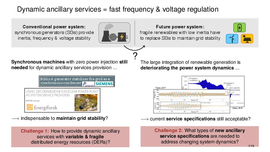
    power system: synchronous generators (SGs) provide inertia, frequency & voltage stability Future power system: fragile renewables with low inertia have to replace SGs to maintain grid stability ? Synchronous machines with zero power injection still needed for dynamic ancillary services provision ... Biblis A generator stabilizes the grid as a synchronous condenser Instrumentation, Controls & Electrical SPPA-E3000 Electrical Solutions makes it possible to use the generator of Biblis A as a synchronous condenser. This serves to even out grid voltage fluctuations. The Plant The Biblis power plant, which has been in a permanently non-productive state, is located in the community of Biblis in the south of Hesse, Germany and belongs to RWE Power AG. Until 2011 it comprised two pressurized water reactors in units A and B, with an output of 1200 MW (unit A) and 1300 MW ( unit B) respectively. Based on the decision of the nuclear energy moratorium, unit A was disconnected from the grid on March 18, 2011. At that time unit B was already in a scheduled revision. The Task As a result of the fluctuating infeed of renewable energy and the shutdown of nuclear power plants in southern Germany, voltage stabilization within the Amprion grid is becoming increasingly challenging. In order to stabilize the grid in the future too, the Biblis A generator was to be converted into a synchronous condenser. This called for a provider capable of implementing this project together with the customer and delivering the requisite major components in the shortest possible time. Our Solution For the first time a generator of this size was converted into a rotating synchronous The Result Ŷ Improved grid stability thanks to the generation of reactive power through the conversion of the generator to a synchronous condenser Ŷ Innovative further use of a shut down power plant Ŷ Optimum planning security and deadline compliance thanks to smooth project handling the generator via the generator terminal lead. It was thus possible to connect the generator from unit A to the grid as a synchronous condenser. This now regulates the reactive power from -400 up to +900 MVar, which is made available to grid operator Amprion in situations of low or high grid voltage. The resulting voltage regulation thus ensures a balanced relationship between active and reactive power. During the start-up procedure of the synchronous condenser, special functions are set in the unit protection. Measures here include deactivation of the underfrequency protection and switching to a sensitive-setting definite time overcurrent protection of the synchronous machine. Even though the customer addressed additional requirements, it was possible to keep the set timeframe of five months for the realization of the project. "The synchronous condenser makes it easier for us to maintain Reference – Electrical Solutions Biblis A generator stabilizes the grid as a synchronous condenser Instrumentation, Controls & Electrical SPPA-E3000 Electrical Solutions makes it possible to use the generator of Biblis A as a synchronous condenser. This serves to even out grid voltage fluctuations. The Plant The Biblis power plant, which has been in a permanently non-productive state, is located in the community of Biblis in the south of Hesse, Germany and belongs to RWE Power AG. Until 2011 it comprised two pressurized water reactors in units A and B, with an output of 1200 MW (unit A) and 1300 MW ( unit B) respectively. Based on the decision of the nuclear energy moratorium, unit A was The Result the generator via the generator terminal lead. It was thus possible to connect the generator from unit A to the grid as a synchronous condenser. This now regulates the reactive power from -400 up to +900 MVar, which is made available to grid operator Amprion in situations of low or high grid voltage. The resulting voltage regulation thus ensures a balanced relationship between active and reactive power. During the start-up procedure of the synchronous condenser, special functions are set in the unit protection. Measures here include deactivation of the underfrequency protection and switching to a sensitive-setting Reference – Electrical Solutions 8/19/18, 14:35 Generator wird zum Motor STARTSEITE → PRESSE 24.02.2012 12:00 24.02.2012 12:00 GENERATOR WIRD ZUM MOTOR Die Spannungshaltung im deutschen Stromnetz wird durch die Einspeisung schwankender erneuerbarer Energien und die Abschaltung von Kernkra werken vor allem im Süden Deutschlands immer anspruchsvoller. Insbesondere im Herbst und Winter kann es hier zu Störungen kommen. Dies hat die Bundesnetzagentur (BNA) in ihrem Bericht zu den Auswirkungen des Kernkra ausstieges auf die Übertragungsnetze und die Versorgungssicherheit im Sommer 2011 deutlich gemacht. Der Übertragungsnetzbetreiber Amprion und RWE Power haben vor diesem Hintergrund vereinbart, den Generator von Block A im nicht-nuklearen Teil des abgeschalteten Kernkra werks Biblis für die Netzdienstleistung ¿Phasenschieberbetrieb¿ umzurüsten und so zur Stabilisierung des Netzes im Süden Deutschlands beizutragen. ¿Der Phasenschieber erleichtert es unseren Ingenieuren, die Systemsicherheit im Amprion-Netz auch in schwierigen Netzsituationen aufrecht zu erhalten¿, so Dr. Klaus Kleinekorte, Technischer Geschä sführer. ¿Die rasche Durchführung dieses ehrgeizigen Projektes war nur möglich, weil alle Beteiligten - Siemens, RWE Power und unsere Mitarbeiter ¿ in den vergangenen Monaten hervorragende Arbeit geleistet haben.¿ Die elektrische Maschine ist technisch so von RWE Power und dem Hersteller Siemens umgerüstet worden, dass der Generator jetzt im Motorbetrieb so genannte Blindleistung regeln kann, die für die Spannungshaltung im Netz dringend benötigt wird. Die ersten Planungen für die umfangreiche und technisch sehr schwierige und aufwändige Umrüstung hatten im Juli vergangenen Jahres begonnen. ¿Uns blieb nicht viel Zeit, denn Amprion wollte den Phasenschieber schon im Februar 2012 in Betrieb nehmen¿, sagte Marcel Lipthal, Projektleiter der Siemens AG. USING DECOMMISSIONED NUCLEAR POWER PLANT AS SYSTEM SERVICE PROVIDERS REPORT 2017:348 NUCLEAR POWER NUCLEAR POWER USING DECOMMISSIONED NUCLEAR POWER PLANT AS SYSTEM SERVICE PROVIDERS REPORT 2017:348 NUCLEAR POWER Biblis A generator stabilizes the grid as a synchronous condenser Instrumentation, Controls & Electrical SPPA-E3000 Electrical Solutions makes it possible to use the generator of Biblis A as a synchronous condenser. This serves to even out grid voltage fluctuations. The Plant The Biblis power plant, which has been in a permanently non-productive state, is located in the community of Biblis in the south of Hesse, Germany and belongs to RWE Power AG. Until 2011 it comprised two pressurized water reactors in units A and B, with an output of 1200 MW (unit A) and 1300 MW ( unit B) respectively. Based on the decision of the nuclear energy moratorium, unit A was disconnected from the grid on March 18, 2011. At that time unit B was already in a scheduled revision. The Task As a result of the fluctuating infeed of renewable energy and the shutdown of nuclear power plants in southern Germany, voltage stabilization within the Amprion grid is becoming increasingly challenging. In order to stabilize the grid in the future too, the Biblis A generator was to be converted into a synchronous condenser. This called for a provider capable of implementing this project together with the customer and delivering the requisite major components in the shortest possible time. Our Solution For the first time a generator of this size was converted into a rotating synchronous condenser by usage of various solutions from The Result Ŷ Improved grid stability thanks to the generation of reactive power through the conversion of the generator to a synchronous condenser Ŷ Innovative further use of a shut down power plant Ŷ Optimum planning security and deadline compliance thanks to smooth project handling the generator via the generator terminal lead. It was thus possible to connect the generator from unit A to the grid as a synchronous condenser. This now regulates the reactive power from -400 up to +900 MVar, which is made available to grid operator Amprion in situations of low or high grid voltage. The resulting voltage regulation thus ensures a balanced relationship between active and reactive power. During the start-up procedure of the synchronous condenser, special functions are set in the unit protection. Measures here include deactivation of the underfrequency protection and switching to a sensitive-setting definite time overcurrent protection of the synchronous machine. Even though the customer addressed additional requirements, it was possible to keep the set timeframe of five months for the realization of the project. "The synchronous condenser makes it easier for us to maintain system security in the grid Reference – Electrical Solutions Biblis A generator stabilizes the grid as a synchronous condenser Instrumentation, Controls & Electrical SPPA-E3000 Electrical Solutions makes it possible to use the generator of Biblis A as a synchronous condenser. This serves to even out grid voltage fluctuations. The Plant The Biblis power plant, which has been in a permanently non-productive state, is located in the community of Biblis in the south of Hesse, Germany and belongs to RWE Power AG. Until 2011 it comprised two pressurized water reactors in units A and B, with an output of 1200 MW (unit A) and 1300 MW ( unit B) respectively. Based on the decision of the nuclear energy moratorium, unit A was disconnected from the grid on March 18, 2011. The Result the generator via the generator terminal lead. It was thus possible to connect the generator from unit A to the grid as a synchronous condenser. This now regulates the reactive power from -400 up to +900 MVar, which is made available to grid operator Amprion in situations of low or high grid voltage. The resulting voltage regulation thus ensures a balanced relationship between active and reactive power. During the start-up procedure of the synchronous condenser, special functions are set in the unit protection. Measures here include deactivation of the underfrequency protection and switching to a sensitive-setting definite time overcurrent protection of the Reference – Electrical Solutions 8/19/18, 14:35 Generator wird zum Motor STARTSEITE → PRESSE 24.02.2012 12:00 24.02.2012 12:00 GENERATOR WIRD ZUM MOTOR Die Spannungshaltung im deutschen Stromnetz wird durch die Einspeisung schwankender erneuerbarer Energien und die Abschaltung von Kernkra werken vor allem im Süden Deutschlands immer anspruchsvoller. Insbesondere im Herbst und Winter kann es hier zu Störungen kommen. Dies hat die Bundesnetzagentur (BNA) in ihrem Bericht zu den Auswirkungen des Kernkra ausstieges auf die Übertragungsnetze und die Versorgungssicherheit im Sommer 2011 deutlich gemacht. Der Übertragungsnetzbetreiber Amprion und RWE Power haben vor diesem Hintergrund vereinbart, den Generator von Block A im nicht-nuklearen Teil des abgeschalteten Kernkra werks Biblis für die Netzdienstleistung ¿Phasenschieberbetrieb¿ umzurüsten und so zur Stabilisierung des Netzes im Süden Deutschlands beizutragen. ¿Der Phasenschieber erleichtert es unseren Ingenieuren, die Systemsicherheit im Amprion-Netz auch in schwierigen Netzsituationen aufrecht zu erhalten¿, so Dr. Klaus Kleinekorte, Technischer Geschä sführer. ¿Die rasche Durchführung dieses ehrgeizigen Projektes war nur möglich, weil alle Beteiligten - Siemens, RWE Power und unsere Mitarbeiter ¿ in den vergangenen Monaten hervorragende Arbeit geleistet haben.¿ Die elektrische Maschine ist technisch so von RWE Power und dem Hersteller Siemens umgerüstet worden, dass der Generator jetzt im Motorbetrieb so genannte Blindleistung regeln kann, die für die Spannungshaltung im Netz dringend benötigt wird. Die ersten Planungen für die umfangreiche und technisch sehr schwierige und aufwändige Umrüstung hatten im Juli vergangenen Jahres begonnen. ¿Uns blieb nicht viel Zeit, denn Amprion wollte den Phasenschieber schon im Februar 2012 in Betrieb nehmen¿, sagte Marcel Lipthal, Projektleiter der Siemens AG. USING DECOMMISSIONED NUCLEAR POWER PLANT AS SYSTEM SERVICE PROVIDERS REPORT 2017:348 NUCLEAR POWER NUCLEAR POWER USING DECOMMISSIONED NUCLEAR POWER PLANT AS SYSTEM SERVICE PROVIDERS REPORT 2017:348 NUCLEAR POWER −→ indispensable to maintain grid stability? Challenge 1: How to provide dynamic ancillary services with variable & fragile distributed energy resources (DERs)? The large integration of renewable generation is deteriorating the power system dynamics ... China, 2019 Texas, 2017 −→ current service specifications still acceptable? Challenge 2: What types of new ancillary service specifications are needed to address changing system dynamics? 1/19
  2. Our solution: Dynamic Virtual Power Plants (DVPP) IDEA: coordinate a

    heterogeneous ensemble of DERs to collectively provide dynamic ancillary services APPROACH: coordination via decentralized control implementation of individual DER units REQUIREMENT: collection of DERs with sufficiently heterogenous capacities & response times GOAL: provide dynamic ancillary services specified as a desired aggregate I/O behavior ≈ 2/19
  3. Problem abstraction in a simple setting • DVPP setup (simplified)

    consisting of – DERs connected at a common bus – input signal broadcasted to all DERs – collect aggregate output signal • ancillary service = aggregate DVPP specification: – desired dynamic response behavior output = Tdes(s) · input – Tdes(s) encodes grid codes while ensuring stability & optimal performance with grid • task: coordinated model matching – design decentralized DER controls so that DVPP behavior matches the aggregate specification i output i ! = Tdes(s) · input – while taking device-level constraints into account DER 1 DER 𝑛 ⋮ ≈ desired aggregate behavior DVPP broadcast input signal aggregate output signal 3/19
  4. Outline utility grid utility grid ≈ aggregate dynamic ancillary services

    specification PV wind BESS DVPP <latexit sha1_base64="Gaj+zIQXBKcYKJjHYCtZouMjiLI=">AAAB+nicbVC7TsMwFHV4lvJKYWSxqJDKUiWoAsYKFsYi9SW1UeQ4TmvVdiLbAVWhn8LCAEKsfAkbf4PTZoCWI1k6Oude3eMTJIwq7Tjf1tr6xubWdmmnvLu3f3BoV466Kk4lJh0cs1j2A6QIo4J0NNWM9BNJEA8Y6QWT29zvPRCpaCzaepoQj6ORoBHFSBvJtyttf8iRHkuehUTNaurct6tO3ZkDrhK3IFVQoOXbX8MwxiknQmOGlBq4TqK9DElNMSOz8jBVJEF4gkZkYKhAnCgvm0efwTOjhDCKpXlCw7n6eyNDXKkpD8xkHlMte7n4nzdIdXTtZVQkqSYCLw5FKYM6hnkPMKSSYM2mhiAsqckK8RhJhLVpq2xKcJe/vEq6F3X3st64b1SbN0UdJXACTkENuOAKNMEdaIEOwOARPINX8GY9WS/Wu/WxGF2zip1j8AfW5w8jhZPu</latexit> Tdes (s) Part I: DVPP control → address challenge 1: how to provide? IEEE Transactions on Power Systems, 2021 IEEE Transactions on Smart Grid, 2023 IEEE Transactions on Smart Grid (u. revision), 2025 22nd Wind & Solar Integration Workshop, 2023 50th IEEE IECON, 2024 16th IEEE Power Tech, 2025 Part II: future dynamic ancillary services → address challenge 2: what to provide? Electric Power System Research, 2024 IEEE Transactions on Power Systems, 2024 IEEE Transactions on Control of Network Systems (u. revision), 2025 62nd IEEE CDC, 2023 4/19
  5. Decentralized DVPP control setup • global broadcast signal ∆f ∆v

    • global aggregated power output ∆pagg ∆qagg = i ∆pi ∆qi • DERs with controllable closed-loop behaviors Ti(s) • overall/global/aggregate DVPP behavior ∆pagg(s) ∆qagg(s) = i Ti(s) ∆f(s) ∆v(s) • desired DVPP specification ∆pdes(s) ∆qdes(s) = Tfp des (s) 0 0 Tvq des (s) Tdes(s) ∆f(s) ∆v(s) → aggregation condition: i Ti(s) = Tdes(s) DVPP: collection of heterogeneous DERs grid-follow. DER n grid-follow. DER 1 . . . ∆f ∆v ∆pagg ∆qagg ∆p1 ∆q1 ∆pn ∆qn plant 1 control 1 T1(s) plant n control n Tn(s) ≈ Tdes(s) ∆pdes ∆qdes ∆f ∆v task: find local controllers such that the aggregation condition & the local DER constraints are satisfied. 5/19
  6. Divide & conquer strategy 1) Disaggregation & pooling desired behavior

    of unit i ... ... Disaggregate Tdes(s) into local desired behaviors via dynamic participation factors (DPFs) Tdes(s) Mi(s) = mfp i (s) 0 0 mvq i (s) Mi(s) · Tdes(s) such that i Ti(s) = Tdes(s) = i Mi(s) · Tdes(s) participation condition i Mi(s) = I2 2) Local matching control plant i matching control i ≈ desired behavior i Mi(s) · Tdes(s) For each unit i, design local matching control to match desired behavior i Ti(s) Ti(s) = Mi(s) · Tdes(s) Häberle, V., Fisher, M., Prieto, E. & Dörfler, F. (2021). Control design of dynamic virtual power plants: an adaptive divide-&-conquer approach. IEEE Transactions on Power Systems. 6/19
  7. Dynamic participation factor (DPF) selection Define DPFs mfp i (s)

    and mvq i (s) of the DVPP units as transfer functions, among others characterized by • a time constant τi for the roll-off frequency • a DC gain mi(0) = ψi to account for power capacity limitations (possibly time-varying due to weather dependency → adaptive DC gain mi(0) = ψi(t)) Divide DVPP units into three categories, i.e., we envision low-pass filter participation units that can provide regulation on longer time scales including steady-state contributions mi(s) = ψi τis+1 frequency amplitude high-pass filter participation units that can provide regulation on very short time scales (fast response capability) mi(s) = τis τis+1 frequency amplitude band-pass filter participation units able to cover the intermediate regime mi(s) = (τi−τj )s (τis+1)(τj s+1) frequency amplitude 7/19
  8. Local matching control Control objective: for each DVPP unit, find

    local matching controllers such that the local closed-loop behavior matches the local desired specification Ti(s) = Mi(s) · Tdes(s) General setup for matching control of unit i • incorporate local desired behavior Mi(s) · Tdes(s) as reference model into conventional converter control architecture • different matching control implementations, e.g., classical PI-based control, robust & optimal H∞ methods, etc. ˙ x = Ax + Bu + Ew y = Cx + Du + Fw Ti(s) K(s) plant i matching control controller local reference model w = ∆f ∆v y = ∆pi ∆qi Mi(s) · Tdes(s) Goal: minimize local matching error! 8/19
  9. Case study Nonlinear & detailed simulation model 2 7 8

    9 3 5 6 4 1 SG 2 SG 3 SG 1 wind PV STATCOM DVPP DVPP specification: frequency & voltage control ∆pdes(s) ∆qdes(s) = Dp+Ms τps+1 0 0 Dq τqs+1 = Tdes(s) ∆f(s) ∆v(s) Participation factor selection 10-1 100 101 10-2 100 102 10-2 10-1 100 10-2 100 102 wind pv statcom sum wind pv statcom sum mfp i (s) mvq i (s) System response during load increase at bus 6 -0.1 -0.05 0 -4 -2 0 2 4 -0.05 0 0.05 -2 0 2 4 6 active power deviation (MW) reactive power deviation (Mvar) voltage deviation (pu) frequency deviation (Hz) 5 25 5 25 wind pv statcom sum wind pv statcom wind pv statcom sum wind pv statcom 9/19
  10. Experimental validation: Multi-converter PHIL testbed SG resisitve load unit grid

    acquisition module MC220 CPU FC 1 ASM SG PLC FC 2 FC 3 main power supply ASM PCC pconv p pconv s p pconv w fref grid pv statcom wind 49.8 50 50.2 0.45 0.5 0.55 0.26 0.28 0.3 0.32 0.34 -0.05 0 0.05 0 5 10 15 20 25 30 0.18 0.2 0.22 wind desired desired desired statcom pv sum desired with DVPP without DVPP • DVPP (wind, PV, STATCOM) for frequency regulation • DVPP response during a ± 1kW load jump • response characteristics according to selected DPFs Andrejewski, M., Häberle, V., Goldschmidt, N., Dörfler, F. & Schulte, H. (2023). Experimental validation of a dynamic virtual power plant control concept based on multi-converter power hardware-in-the-loop test bench, 22nd Wind and Solar Integration Workshop. 10/19
  11. DVPP extensions coupled Tdes(s) Tdes(s) = Tfp des (s) Tvp

    des (s) Tfq des (s) Tvq des (s) noncontrollable units 4 1 hydro BESS super- capacitor DVPP 10-2 100 102 10-3 10-2 10-1 100 101 grid-forming DVPP ∆fdes(s) ∆vdes(s) = Tdes(s) ∆p ∆q adaptive DPF active power before cloud during cloud spatially distributed POC 1 POC r remaining power system DVPP area ≈ Tdes(s) DVPP POC 1 POC r remaining power system DVPP area others • complex-frequency DVPP • DC DVPP • ... Häberle, V., Fisher, M., Prieto, E. & Dörfler, F. (2021). Control design of dynamic virtual power plants: an adaptive divide-&-conquer approach. IEEE Transactions on Power Systems. Häberle, V., Tayyebi, A., He, X., Prieto, E. & Dörfler, F. (2023). Grid-forming & spatially distributed control design of dynamic virtual power plants. IEEE Transactions on Smart Grid. Domingo, R., Häberle, V., He, X., & Dörfler, F. (2024). Dynamic complex frequency control of grid-forming converters. Annual Conference of IEEE Industrial Electronics Society. He, X., Duarte, J., Häberle, V., & Dörfler, F. (2024). Grid-forming control of modular dynamic virtual power plants. IEEE Transactions on Smart Grid (under revision). 11/19
  12. Outline utility grid utility grid ≈ aggregate dynamic ancillary services

    specification PV wind BESS DVPP <latexit sha1_base64="Gaj+zIQXBKcYKJjHYCtZouMjiLI=">AAAB+nicbVC7TsMwFHV4lvJKYWSxqJDKUiWoAsYKFsYi9SW1UeQ4TmvVdiLbAVWhn8LCAEKsfAkbf4PTZoCWI1k6Oude3eMTJIwq7Tjf1tr6xubWdmmnvLu3f3BoV466Kk4lJh0cs1j2A6QIo4J0NNWM9BNJEA8Y6QWT29zvPRCpaCzaepoQj6ORoBHFSBvJtyttf8iRHkuehUTNaurct6tO3ZkDrhK3IFVQoOXbX8MwxiknQmOGlBq4TqK9DElNMSOz8jBVJEF4gkZkYKhAnCgvm0efwTOjhDCKpXlCw7n6eyNDXKkpD8xkHlMte7n4nzdIdXTtZVQkqSYCLw5FKYM6hnkPMKSSYM2mhiAsqckK8RhJhLVpq2xKcJe/vEq6F3X3st64b1SbN0UdJXACTkENuOAKNMEdaIEOwOARPINX8GY9WS/Wu/WxGF2zip1j8AfW5w8jhZPu</latexit> Tdes (s) Part I: DVPP control → address challenge 1: how to provide? IEEE Transactions on Power Systems, 2021 IEEE Transactions on Smart Grid, 2023 IEEE Transactions on Smart Grid (u. revision), 2025 22nd Wind & Solar Integration Workshop, 2023 50th IEEE IECON, 2024 16th IEEE Power Tech, 2025 Part II: future dynamic ancillary services → address challenge 2: what to provide? Electric Power System Research, 2024 IEEE Transactions on Power Systems, 2024 IEEE Transactions on Control of Network Systems (u. revision), 2025 62nd IEEE CDC, 2023 12/19
  13. From grid codes to feasible transfer functions • translate piece-wise

    linear time-domain grid code curves into parametric transfer functions ∆p(s) ∆q(s) = Tfp des (s, αfp) 0 0 Tvq des (s, αvq) = Tdes(s,α) ∆f(s) ∆v(s) −→ parameters α need to satisfy grid code requirements & device-level constraints • superposition of different ancillary services Tfp des (s, αfp) = Tfcr des (s, αfcr) FCR + Tffr des (s, αffr) FFR + ... |∆p| t tfcr a |∆pfcr| tfcr i exact Tfcr des (s, αfcr) minimum grid code Example: FCR Capability Curve (EU 2016/631) • active power capability curve after frequency drop • parameterized by time constants αfcr := [tfcr i , tfcr a ] • grid code requirements on FCR capacity |∆pfcr| 0 ≤ tfcr i ≤ tfcr i,max & tfcr i ≤ tfcr a ≤ tfcr a,max • device-level ramping rate constraint |∆pfcr| ≤ tfcr a − tfcr i · rp max Goal: optimize response over α & grid perception Häberle, V., Huang, L., He, X., Prieto, E., Dörfler, F. (2024). Dynamic ancillary services: From grid codes to transfer function-based convert. ctrl. Electric Power Systems Research. 13/19
  14. Optimal dynamic ancillary services provision: Perceive & Optimize (P&O) reserve

    unit(s) control PCC utility grid G(s) e.g., DVPP ≈ Tdes(s, α) “Perceive” unknown & local grid dynamics → identify grid dynamic equivalent G(s) ∆f(s) ∆v(s) = G11(s) G12(s) G21(s) G22(s) =:G(s) ∆p(s) ∆q(s) → takes into account local grid characteristics: sensitivity, short circuit & R/L ratios, etc. G(s) Tdes(s, α⋆) grid equivalent ancillary services specification input disturbance performance output to be minimized optimization problem α⋆ ∆p ∆q ∆f ∆v “Optimize” device response subject to constraints • ensure grid code & device-level requirements • stable closed-loop interconnection of grid equivalent G(s) & parametric service Tdes(s, α) → optimize for feasible α⋆ which results in best closed-loop & system-level performance Häberle, V., He, X, Huang, L, Prieto, E. & Dörfler, F. (2024). Optimal dynamic ancillary services provision based on local power grid perception. IEEE Transactions on Power Systems. 14/19
  15. Closed-loop power grid optimization “Optimize” • closed-loop interconnection of G(s)

    and parametric Tdes(s, α) • optimize for α⋆ to get optimal & stable closed-loop performance G(s) Tdes(s, α⋆) grid equivalent ancillary services specification input disturbance performance output to be minimized optimization problem α⋆ ∆p ∆q ∆f ∆v parametric in α minimize α frequency deviation + RoCoF + voltage peak s.t. dynamics: identified grid equivalent ancillary services specification grid-code constraints device-level constraints Solution: smooth objective → compute explicit gradient + project on constraints + scalable first-order methods 15/19
  16. Case studies 2-area Kundur system • two additional reserve units

    (e.g., representing DVPPs) • detailed (nonlinear, EMT) models 1 7 6 11 3 9 8 2 SG 1 SG 4 SG 2 5 10 SG 3 4 13 reserve unit 1 12 reserve unit 2 Case studies to demonstrate the effectiveness of the P&O strategy: Cheap ancillary services: Tdes(α0, s) • encodes minimum open-loop grid-code requirements • cheap, but feasible dynamic ancillary services provision • indistinguishable for any grid location |∆p| t tfcr a |∆pfcr| tfcr i Tfcr des (s, α0) minimum grid code 16/19
  17. Case study I • nominal grid conditions • apply P&O

    strategy for unit 1, keep unit 2 disconnected • initial situation: cheap ancillary services provision by reserve unit 1 1 6 2 SG 1 SG 2 5 reserve unit 1 G1(s) 12 0 10 20 30 40 50 -0.25 -0.2 -0.15 -0.1 -0.05 0 0 10 20 30 40 50 -0.05 -0.04 -0.03 -0.02 -0.01 0 0.01 2 2.1 2.2 2.3 2.4 2.5 -0.2 -0.15 -0.1 -0.05 0 2 2.1 2.2 2.3 2.4 2.5 -0.04 -0.02 0 cheap optimal cheap optimal System response during load increase at bus 7 12.6% improvement in RoCoF 11.6% improvement in frequency nadir 32.9% reduction in voltage peak -80 -60 -40 -80 -60 -40 10 0 10 2 400 600 800 10 0 10 2 400 500 600 -30 -20 -10 0 -20 -10 0 10 0 10 2 0 200 400 10 0 10 2 300 350 400 reference identified 17/19
  18. Case study II • oscillatory grid with weakly-damped inter-area modes

    • sequentially apply P&O strategy for both units • initial situation: cheap ancillary services by both units 1 6 2 SG 1 SG 2 5 reserve unit 1 G1(s) 12 G2(s) 11 3 9 8 SG 4 10 SG 3 4 13 reserve unit 2 0 10 20 30 40 50 -0.5 -0.4 -0.3 -0.2 -0.1 0 0.1 0 10 20 30 40 50 -0.015 -0.01 -0.005 0 0.005 0.01 0.015 0.02 0.025 cheap 1 & cheap 2 optimal 1 & cheap 2 optimal 1 & optimal 2 cheap 1 & cheap 2 optimal 1 & cheap 2 optimal 1 & optimal 2 significant improvement of the closed-loop system behavior after first & second P&O cycle during a load increase at bus 7 -100 -50 0 -50 0 10 0 10 2 100 200 300 10 0 10 2 400 500 600 -40 -20 0 20 -20 -10 0 10 0 10 2 0 200 400 10 0 10 2 300 350 400 reference identified G1(s) inter-area mode 18/19
  19. Conclusions Part I: DVPP control Part II: future dynamic ancillary

    services utility grid utility grid ≈ PV wind BESS <latexit sha1_base64="Gaj+zIQXBKcYKJjHYCtZouMjiLI=">AAAB+nicbVC7TsMwFHV4lvJKYWSxqJDKUiWoAsYKFsYi9SW1UeQ4TmvVdiLbAVWhn8LCAEKsfAkbf4PTZoCWI1k6Oude3eMTJIwq7Tjf1tr6xubWdmmnvLu3f3BoV466Kk4lJh0cs1j2A6QIo4J0NNWM9BNJEA8Y6QWT29zvPRCpaCzaepoQj6ORoBHFSBvJtyttf8iRHkuehUTNaurct6tO3ZkDrhK3IFVQoOXbX8MwxiknQmOGlBq4TqK9DElNMSOz8jBVJEF4gkZkYKhAnCgvm0efwTOjhDCKpXlCw7n6eyNDXKkpD8xkHlMte7n4nzdIdXTtZVQkqSYCLw5FKYM6hnkPMKSSYM2mhiAsqckK8RhJhLVpq2xKcJe/vEq6F3X3st64b1SbN0UdJXACTkENuOAKNMEdaIEOwOARPINX8GY9WS/Wu/WxGF2zip1j8AfW5w8jhZPu</latexit> Tdes (s) Challenge 1: How to provide dynamic ancillary services with variable & fragile power- electronics-based generation units? Challenge 2: What types of new ancillary service specifications are needed to address changing system dynamics? Ongoing & Future work • extension of P&O strategy to multi-agent scenarios: what if many DERs learn in parallel ? • development of next-generation grid codes: decentralized stability certificates, service criteria, ... 19/19