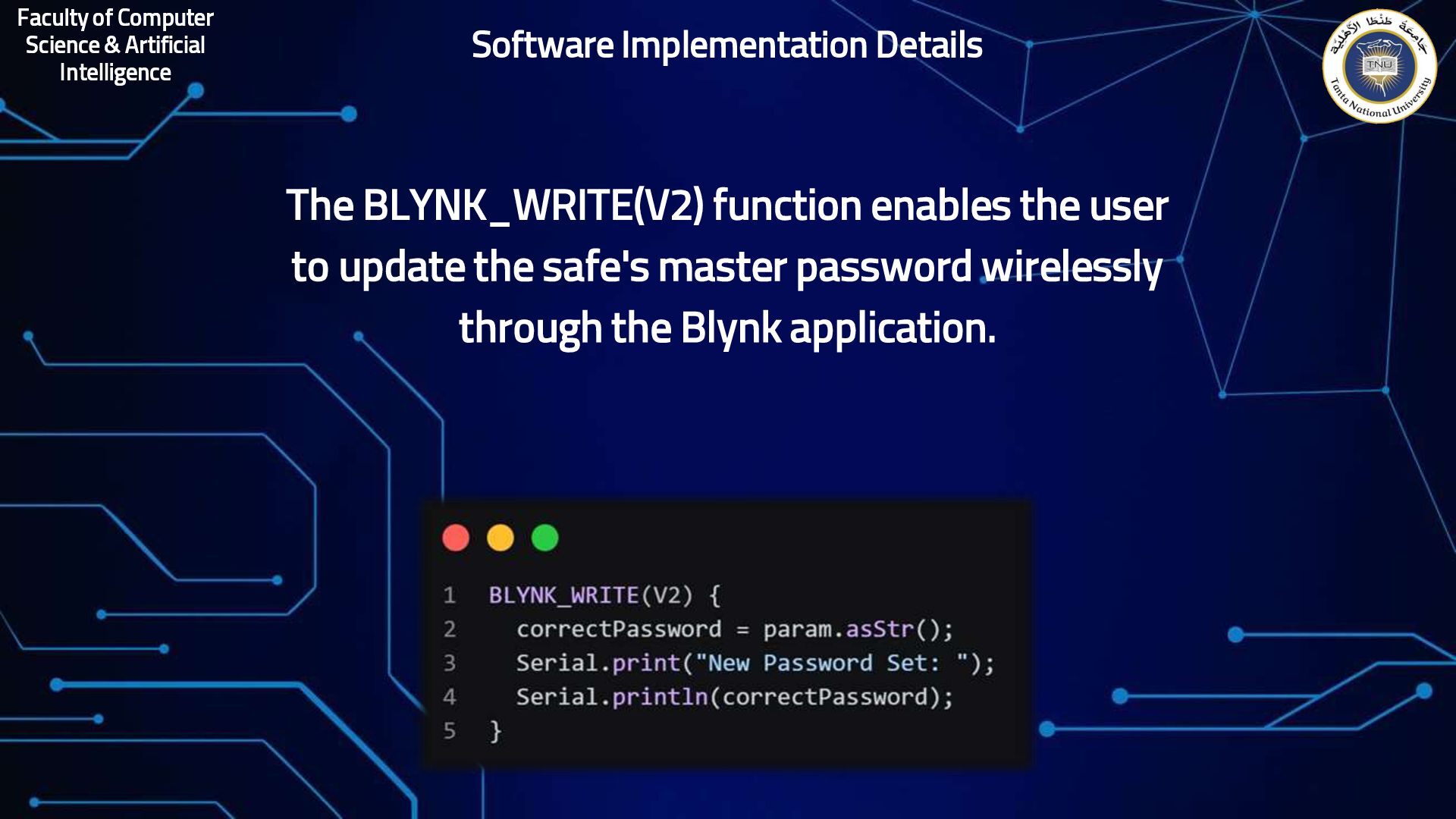
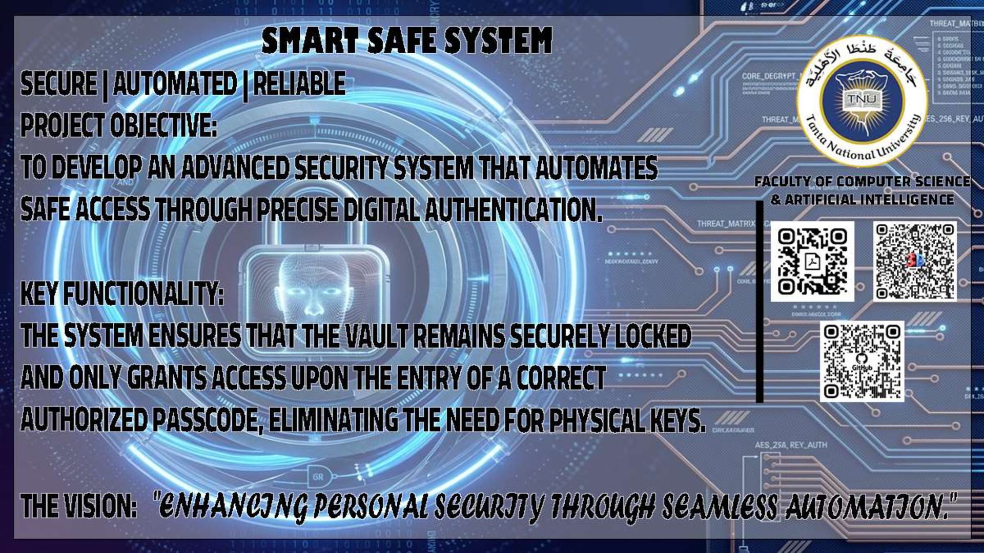
logic-based security system designed to control safe access electronically. Mechanism: Uses digital comparators to match user input with a pre-set password. Security: Features an automatic alarm trigger after three consecutive failed attempts. Monitoring: Real-time status display using LEDs and 7-Segment displays. Storage: Employs Flip-Flops and Registers for data retention and state control. Objective: To build a reliable, hardware-efficient security prototype using logic gates
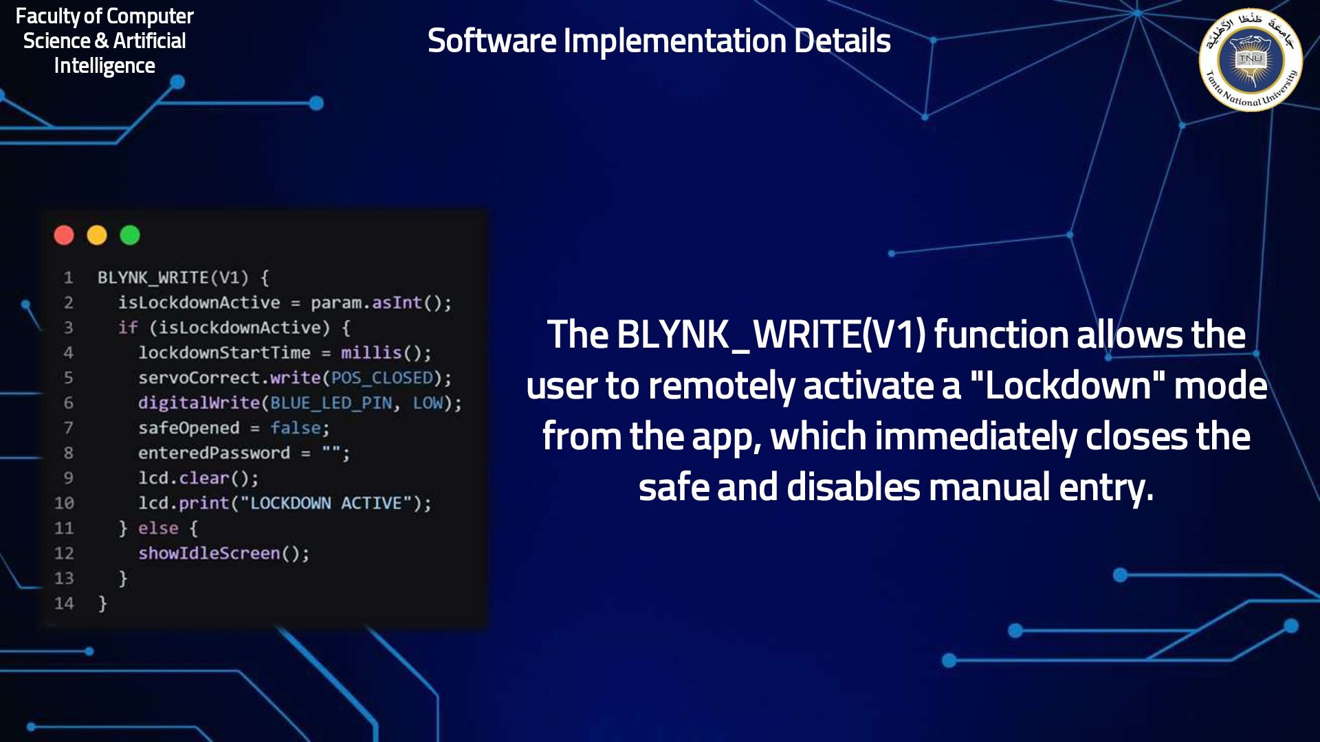
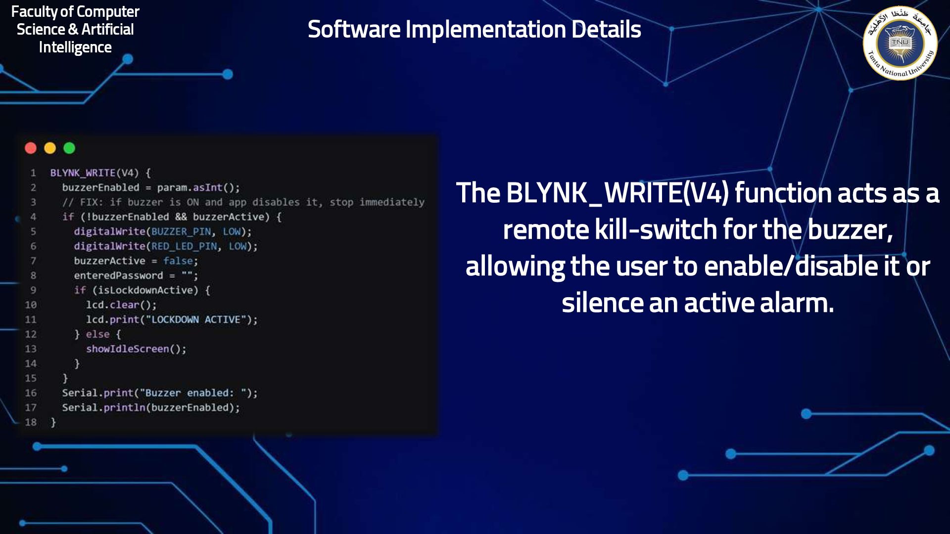
allows the user to remotely activate a "Lockdown" mode from the app, which immediately closes the safe and disables manual entry. Software Implementation Details
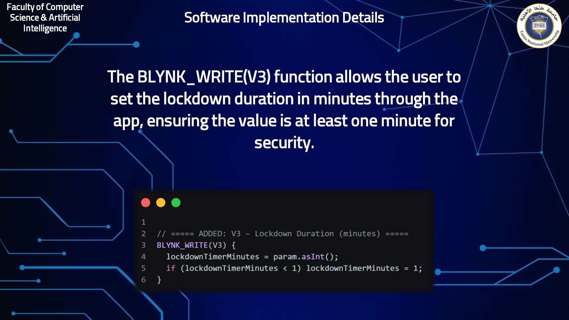
allows the user to set the lockdown duration in minutes through the app, ensuring the value is at least one minute for security. Software Implementation Details
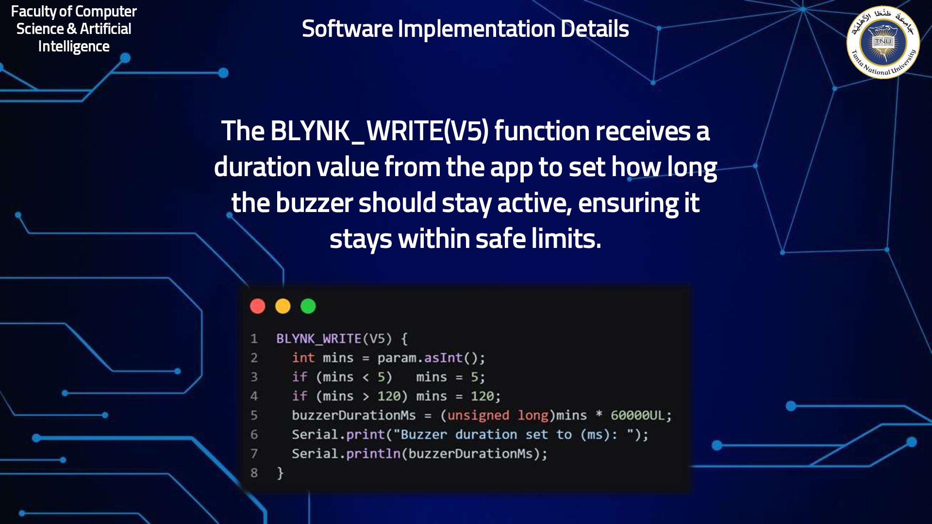
receives a duration value from the app to set how long the buzzer should stay active, ensuring it stays within safe limits. Software Implementation Details
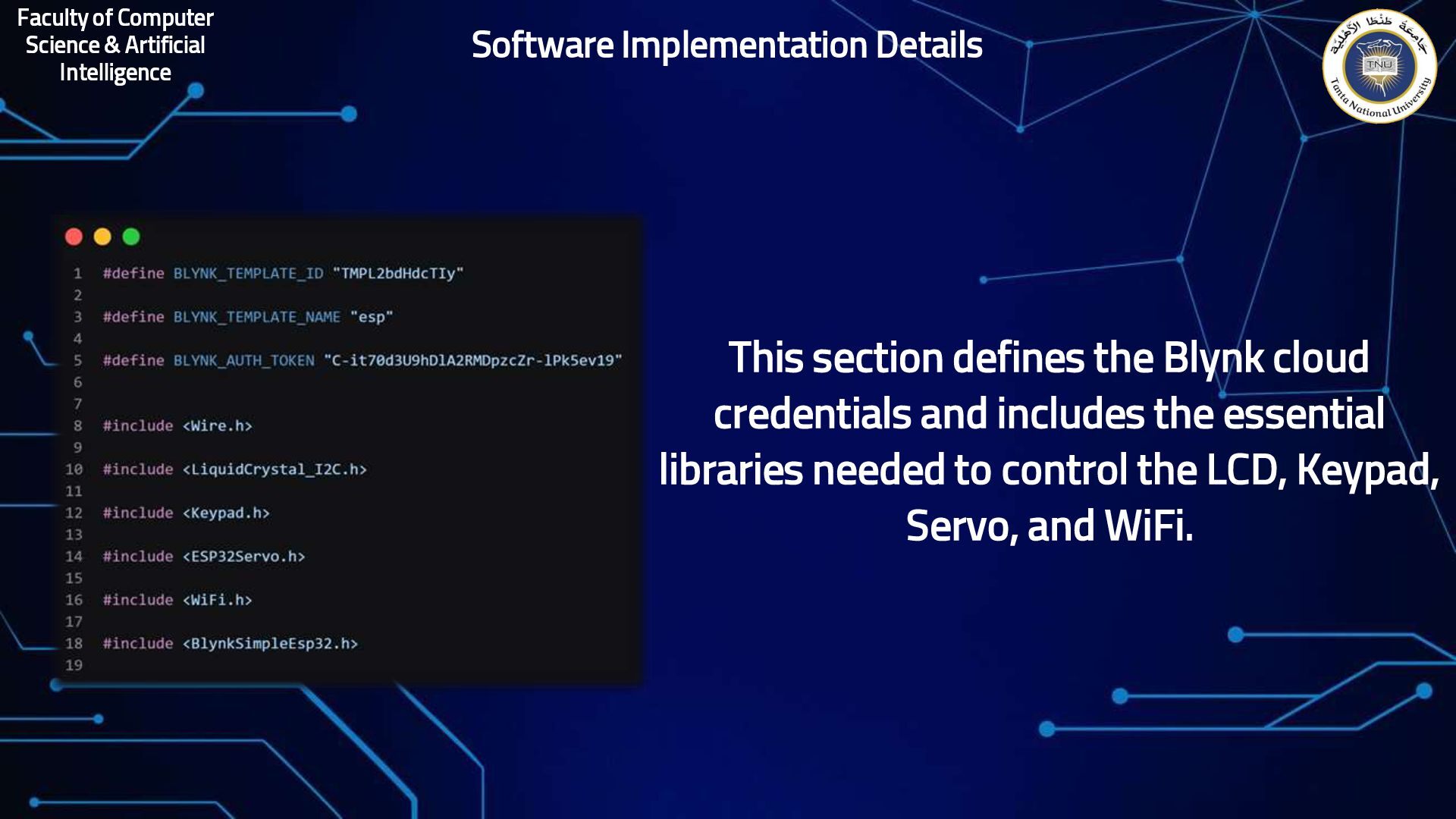
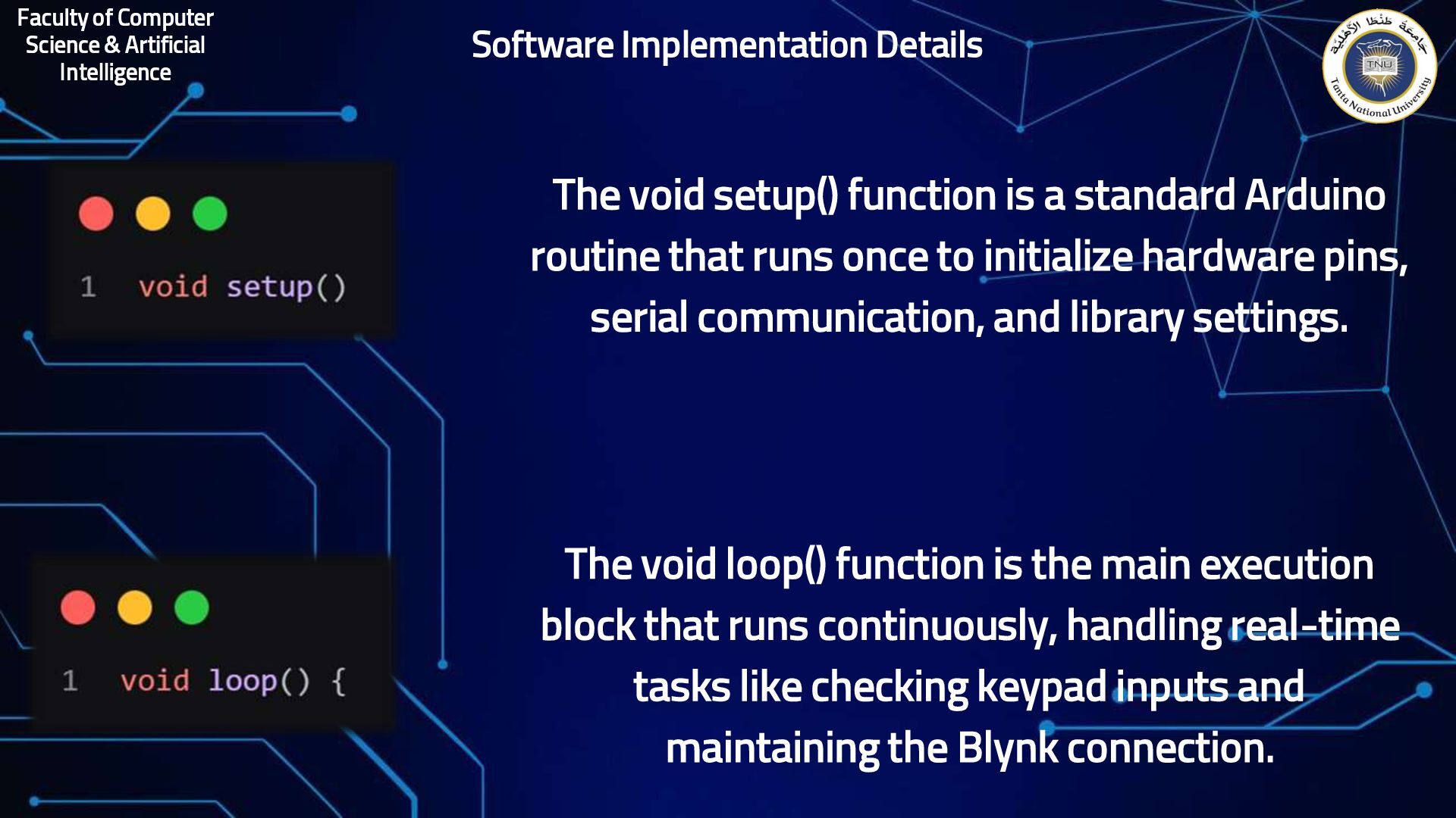
function is a standard Arduino routine that runs once to initialize hardware pins, serial communication, and library settings. The void loop() function is the main execution block that runs continuously, handling real-time tasks like checking keypad inputs and maintaining the Blynk connection. Software Implementation Details
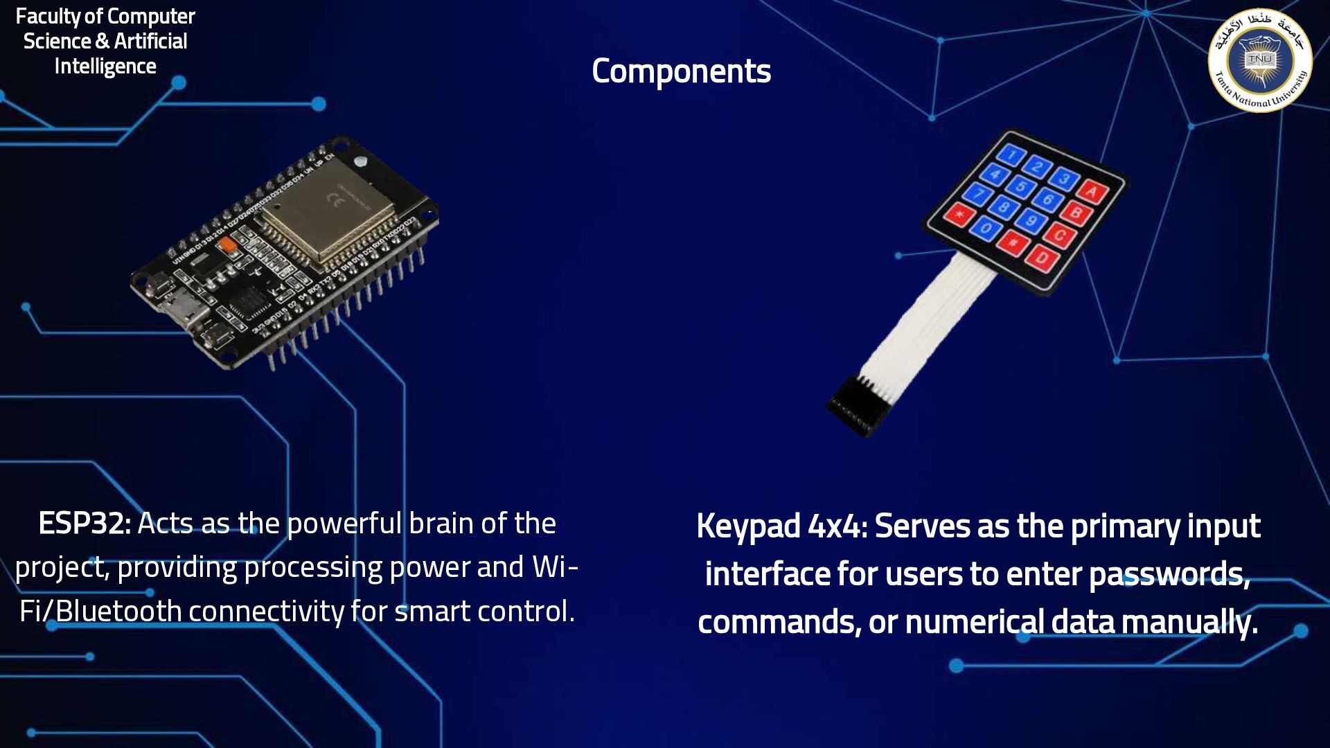
the powerful brain of the project, providing processing power and Wi- Fi/Bluetooth connectivity for smart control. Components Keypad 4x4: Serves as the primary input interface for users to enter passwords, commands, or numerical data manually.
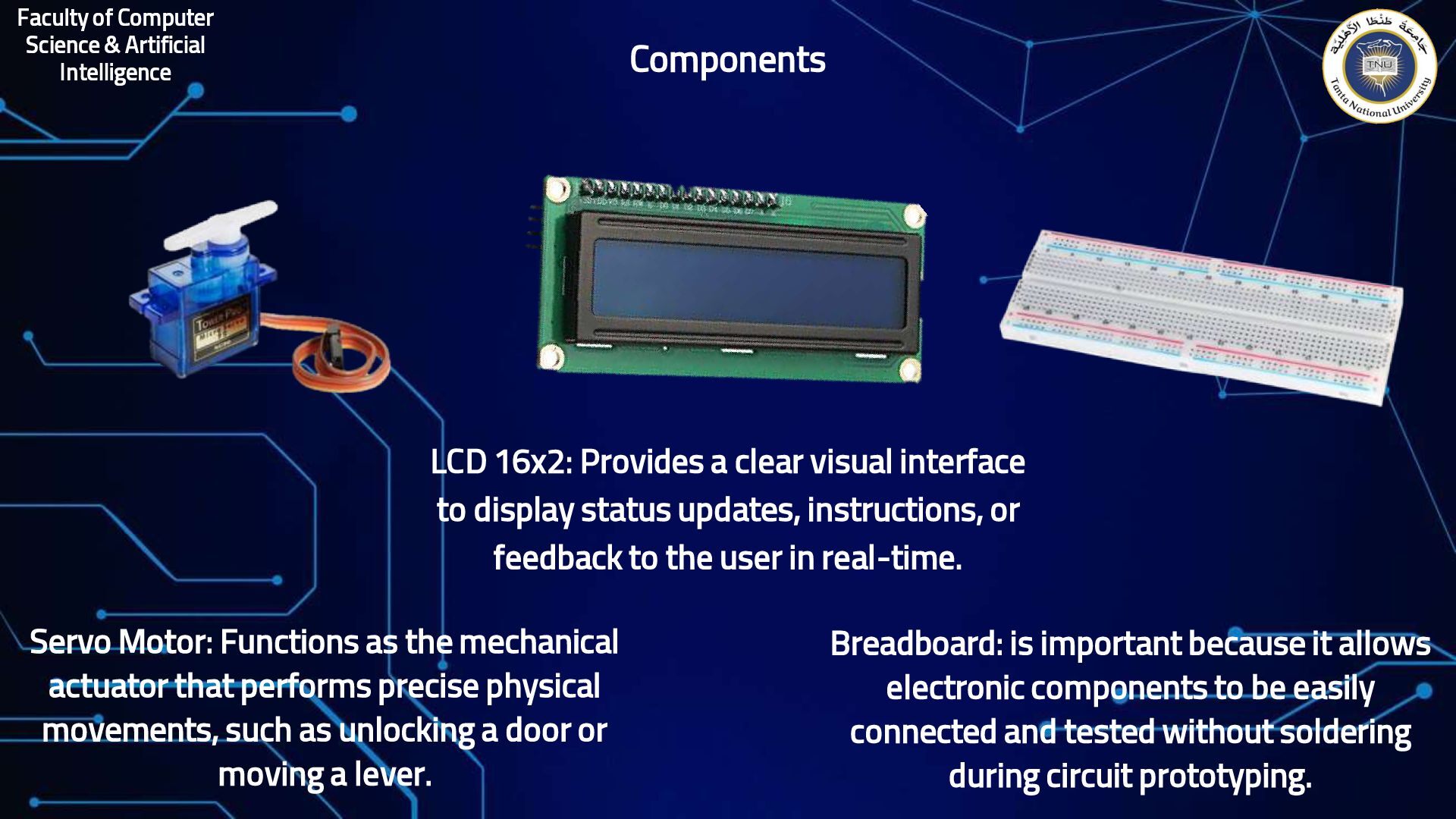
Functions as the mechanical actuator that performs precise physical movements, such as unlocking a door or moving a lever. LCD 16x2: Provides a clear visual interface to display status updates, instructions, or feedback to the user in real-time. Breadboard: is important because it allows electronic components to be easily connected and tested without soldering during circuit prototyping.
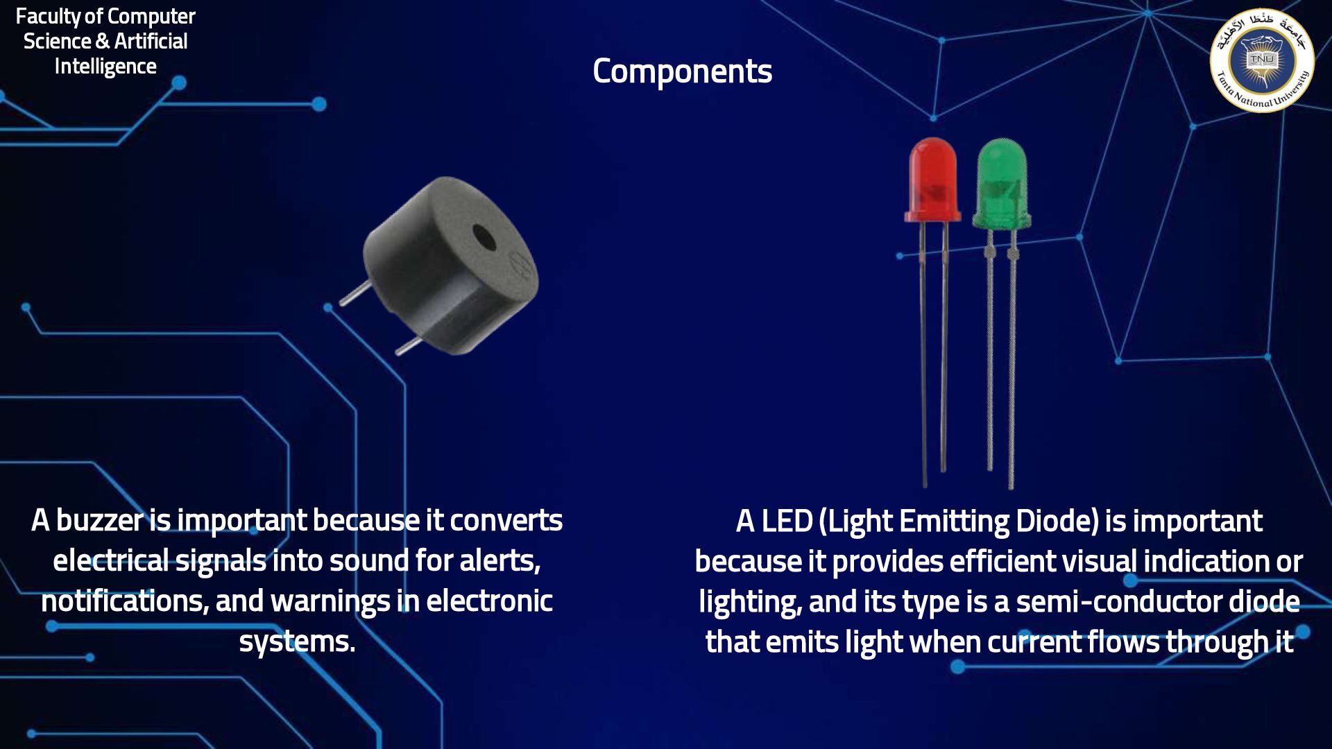
important because it converts electrical signals into sound for alerts, notifications, and warnings in electronic systems. Components A LED (Light Emitting Diode) is important because it provides efficient visual indication or lighting, and its type is a semi-conductor diode that emits light when current flows through it
project demonstrates a security system using the ESP32 as a central processing unit to manage user authentication and physical access. The system utilizes a 4x4 Keypad for data entry, an LCD 16x2 for visual feedback, and a Servo Motor as the locking mechanism. Logic-Based Hardware Integration Features
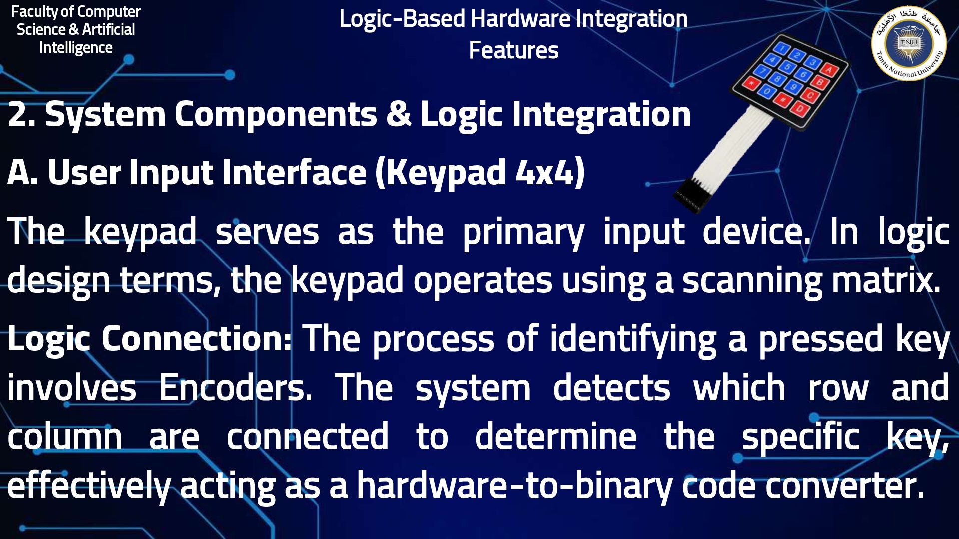
& Logic Integration A. User Input Interface (Keypad 4x4) The keypad serves as the primary input device. In logic design terms, the keypad operates using a scanning matrix. Logic Connection: The process of identifying a pressed key involves Encoders. The system detects which row and column are connected to determine the specific key, effectively acting as a hardware-to-binary code converter. Logic-Based Hardware Integration Features
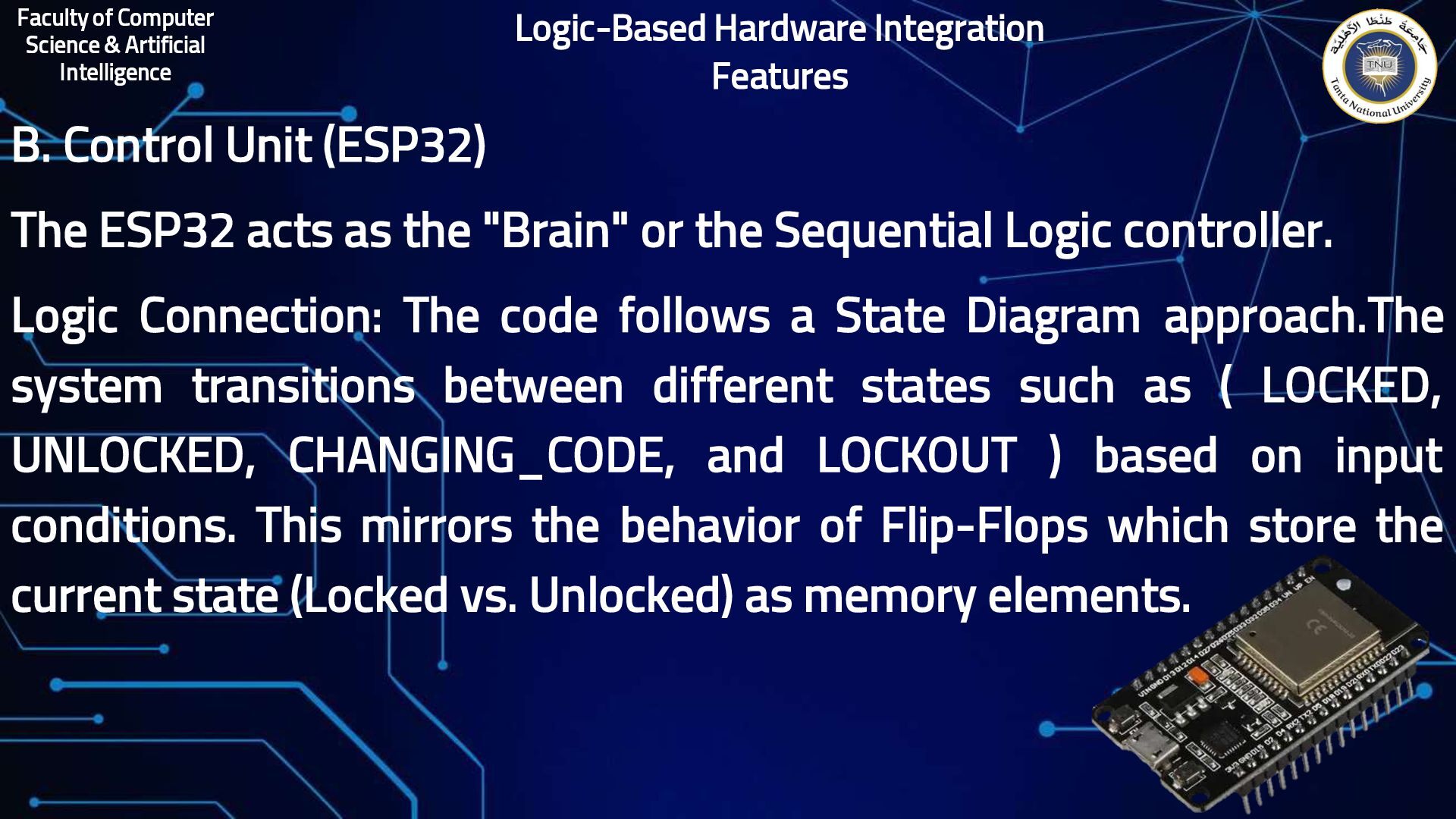
(ESP32) The ESP32 acts as the "Brain" or the Sequential Logic controller. Logic Connection: The code follows a State Diagram approach.The system transitions between different states such as ( LOCKED, UNLOCKED, CHANGING_CODE, and LOCKOUT ) based on input conditions. This mirrors the behavior of Flip-Flops which store the current state (Locked vs. Unlocked) as memory elements. Logic-Based Hardware Integration Features
(Comparator) When a user enters a code, the software compares inputCode with masterCode. Logic Connection: This is a digital implementation of a Magnitude Comparator. Just as a logic circuit compares two binary numbers to check if A=B, the ESP32 performs a bit-by-bit comparison to grant or deny access. Logic-Based Hardware Integration Features
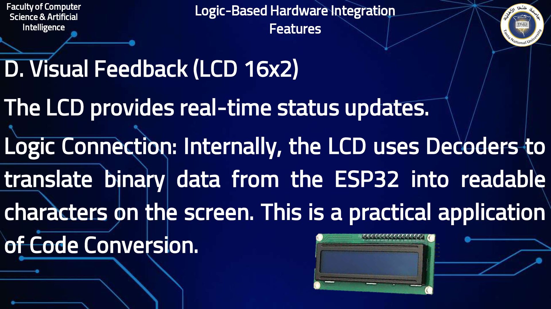
(LCD 16x2) The LCD provides real-time status updates. Logic Connection: Internally, the LCD uses Decoders to translate binary data from the ESP32 into readable characters on the screen. This is a practical application of Code Conversion. Logic-Based Hardware Integration Features
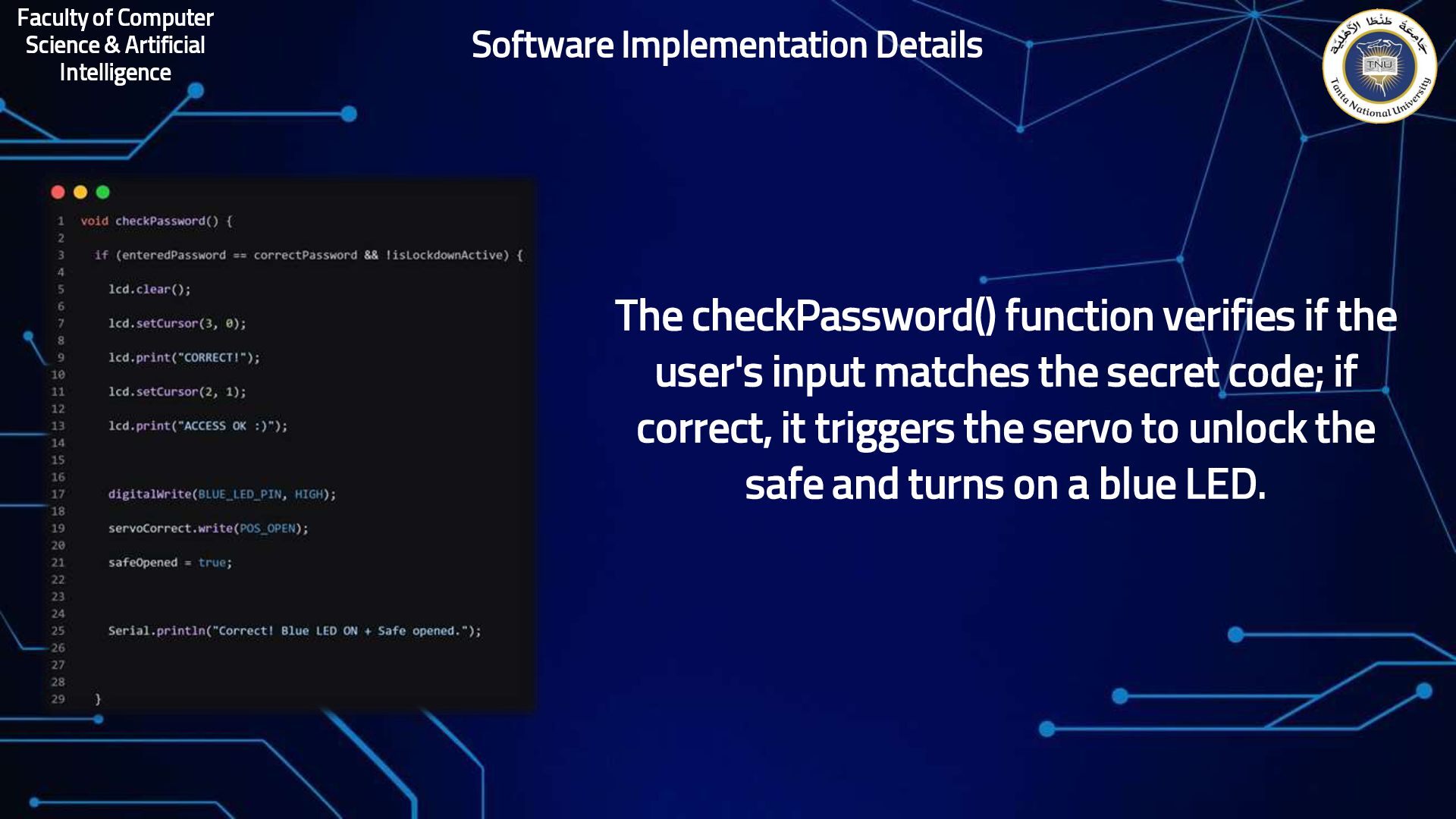
verifies if the user's input matches the secret code; if correct, it triggers the servo to unlock the safe and turns on a blue LED. Software Implementation Details
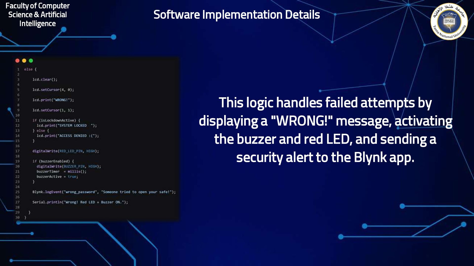
failed attempts by displaying a "WRONG!" message, activating the buzzer and red LED, and sending a security alert to the Blynk app. Software Implementation Details
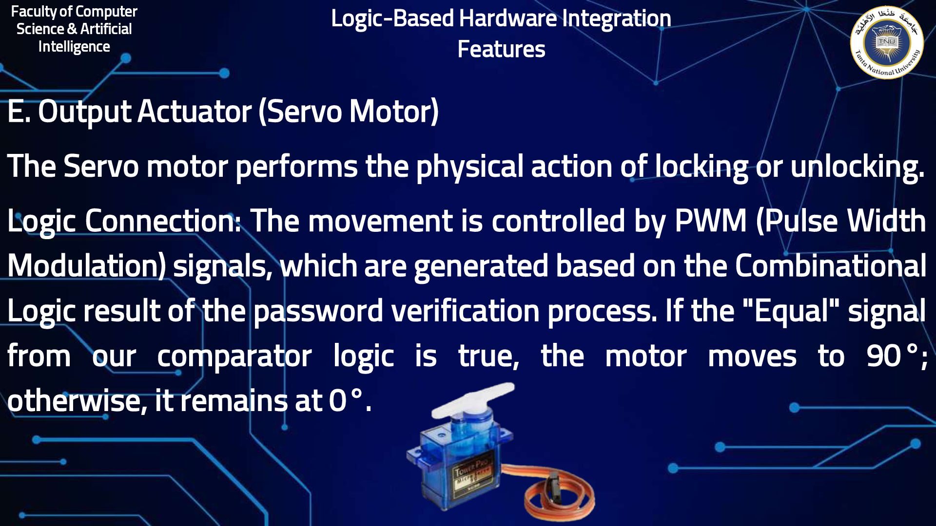
(Servo Motor) The Servo motor performs the physical action of locking or unlocking. Logic Connection: The movement is controlled by PWM (Pulse Width Modulation) signals, which are generated based on the Combinational Logic result of the password verification process. If the "Equal" signal from our comparator logic is true, the motor moves to 90°; otherwise, it remains at 0°. Logic-Based Hardware Integration Features
completes the circuit loop for all modules, while 5V/VIN powers high-demand components like the LCD and Servo.LCD Interface: Uses I2C protocol where SDA (21) transfers data and SCL (22) synchronizes timing, acting as a Decoder for visual output.Servo Control: Managed via GPIO 17 (TXD) which sends serial commands, utilizing Sequential Logic and counters to regulate the rotation angle.Input Encoding: The Keypad uses an Encoding process, mapped to ADC1/ADC2 for analog/touch sensing and DAC for real analog voltage conversion.Feedback Logic: The Red LED (18) follows the SCL clock, while the Green LED (19) uses MISO for master-input data reception.Buzzer Alert: Connected to GPIO 4, it leverages ADC2 and Touch capabilities to provide audible security feedback. Circuit Connection Explanation
3. Operational Logic Flow Initialization: The system starts in a LOCKED state, a default power-up condition often managed by Registers. Input Processing: As digits are entered, they are temporarily stored in a buffer, similar to a Shift Register capturing serial data. Security Constraints: The failedAttempts counter acts as a Synchronous Up Counter. Once the counter reaches the MAX_ATTEMPTS , the system triggers a LOCKOUT state using a Timing Diagram sequence to disable inputs for 30 seconds. Programming Mode: The system allows for a "Code Change." This involves updating the stored values in the controller’s memory, representing a rewrite of the system's Boolean Functions for access.
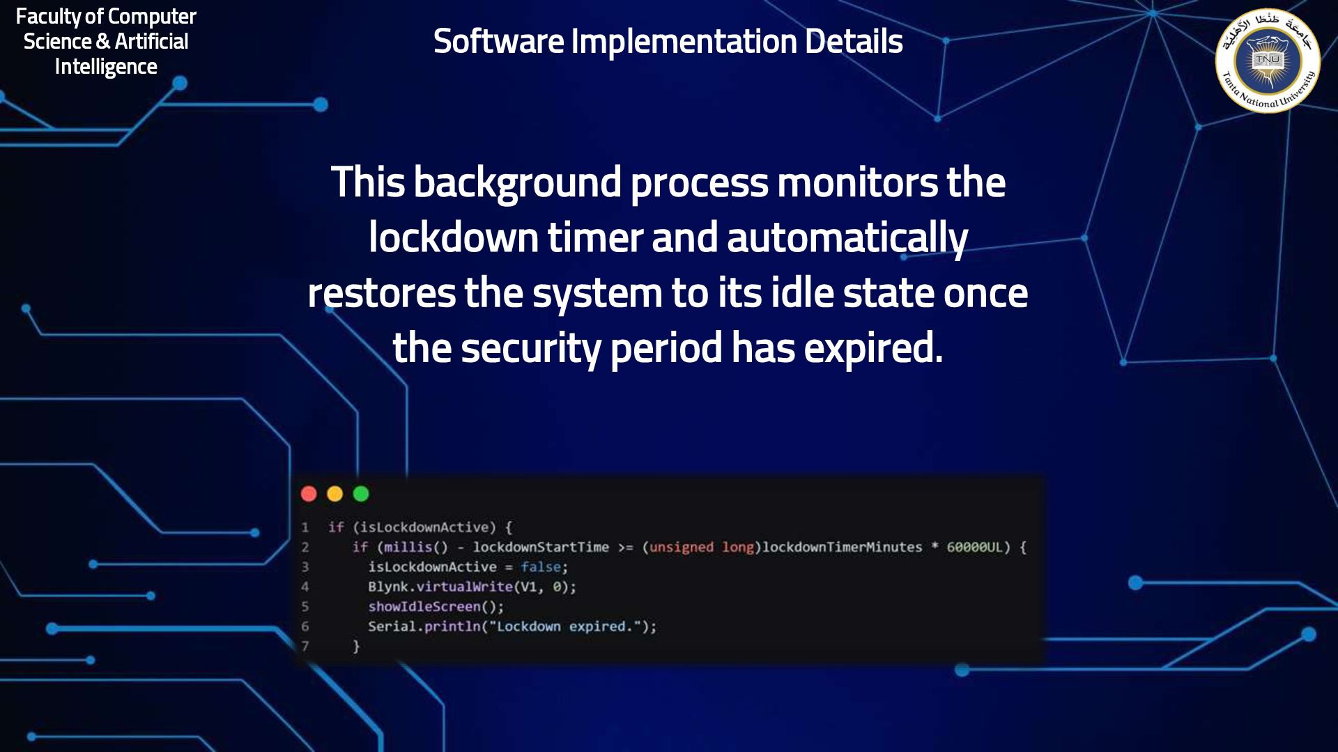
monitors the lockdown timer and automatically restores the system to its idle state once the security period has expired. Software Implementation Details
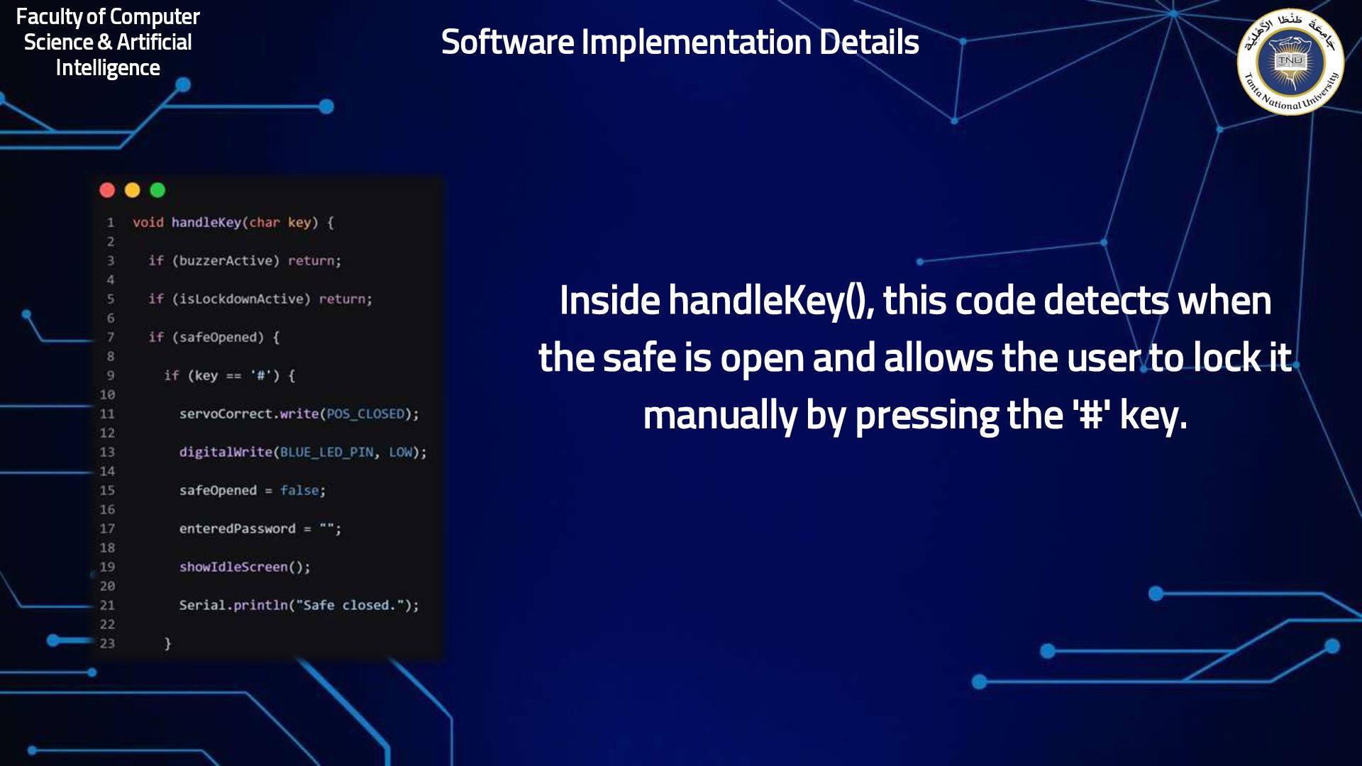
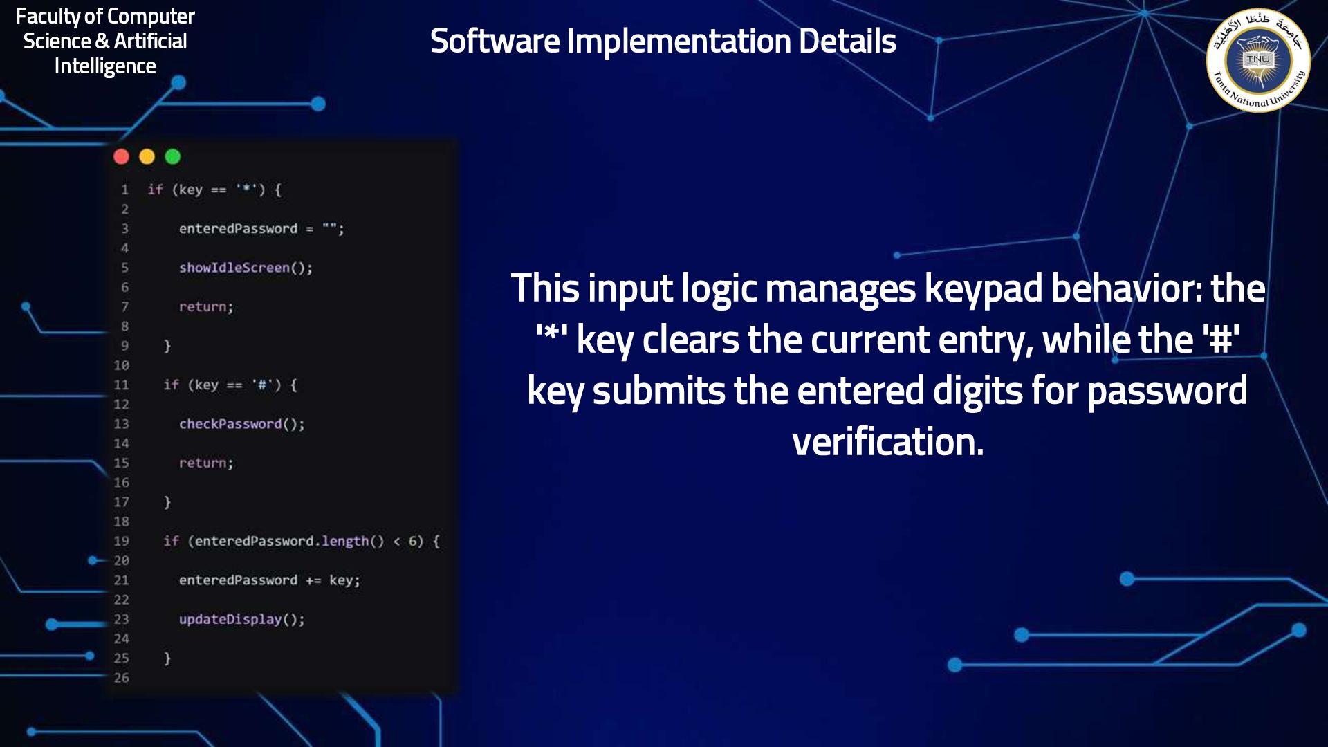
manages keypad behavior: the '*' key clears the current entry, while the '#' key submits the entered digits for password verification. Software Implementation Details


 coderdojojapan
 robintux
 akiraasano
 signer
 bvr7352
 kaityo256
 masakiokuda
 juanmartin2026
 bunnchinn3
 techseoconnect
 mfonobong
 hatefulcrawdad
 addyosmani
 sferik
 chikuwait
 afnizarnur
 cassininazir
 holman
 varn