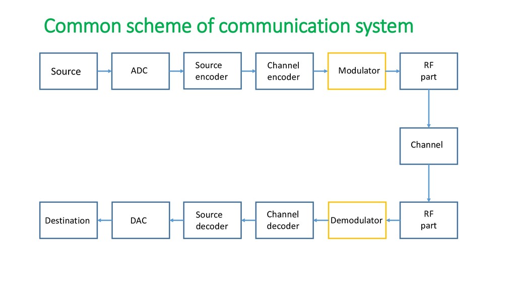
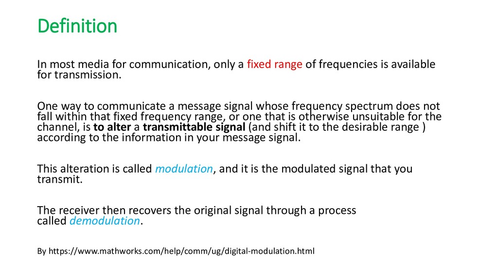
of frequencies is available for transmission. One way to communicate a message signal whose frequency spectrum does not fall within that fixed frequency range, or one that is otherwise unsuitable for the channel, is to alter a transmittable signal (and shift it to the desirable range ) according to the information in your message signal. This alteration is called modulation, and it is the modulated signal that you transmit. The receiver then recovers the original signal through a process called demodulation. By https://www.mathworks.com/help/comm/ug/digital-modulation.html
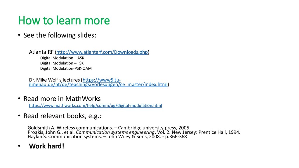
RF (http://www.atlantarf.com/Downloads.php) Digital Modulation – ASK Digital Modulation – FSK Digital Modulation-PSK-QAM Dr. Mike Wolf’s lectures (https://www5.tu- ilmenau.de/nt/de/teachings/vorlesungen/ce_master/index.html) • Read more in MathWorks https://www.mathworks.com/help/comm/ug/digital-modulation.html • Read relevant books, e.g.: Goldsmith A. Wireless communications. – Cambridge university press, 2005. Proakis, John G., et al. Communication systems engineering. Vol. 2. New Jersey: Prentice Hall, 1994. Haykin S. Communication systems. – John Wiley & Sons, 2008. - p.366-368 • Work hard!
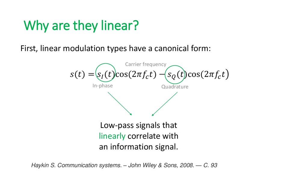
canonical form: () = ()cos(2 ) − ()cos(2 In-phase Quadrature Carrier frequency Low-pass signals that linearly correlate with an information signal. Haykin S. Communication systems. – John Wiley & Sons, 2008. — C. 93
consideration of the carrier frequency and bit duration. Bits Complex symbols 00 0,7+0,7i 01 0,7-0,7i 10 -0,7+0,7i 11 -0,7-0,7i Baseband representation (e.g. QPSK) The baseband analogs can be used for research due to the main properties depend on the envelope (complex symbols).
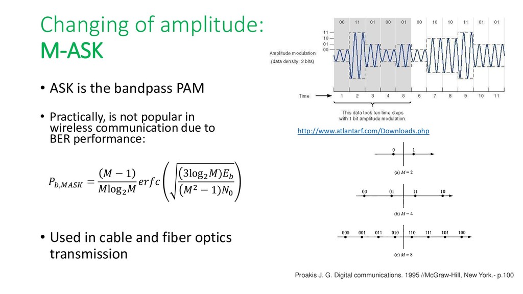
, = − 1 log2 3log2 ) 2 − 1)0 http://www.atlantarf.com/Downloads.php • Practically, is not popular in wireless communication due to BER performance: • Used in cable and fiber optics transmission Proakis J. G. Digital communications. 1995 //McGraw-Hill, New York.- p.100
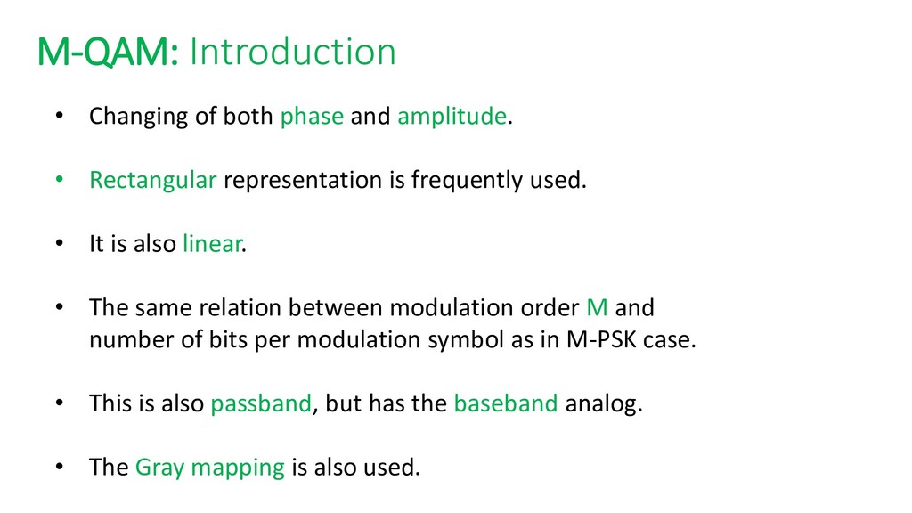
Rectangular representation is frequently used. • It is also linear. • The same relation between modulation order M and number of bits per modulation symbol as in M-PSK case. • This is also passband, but has the baseband analog. • The Gray mapping is also used.
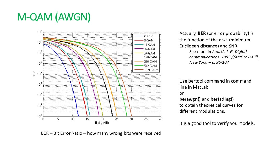
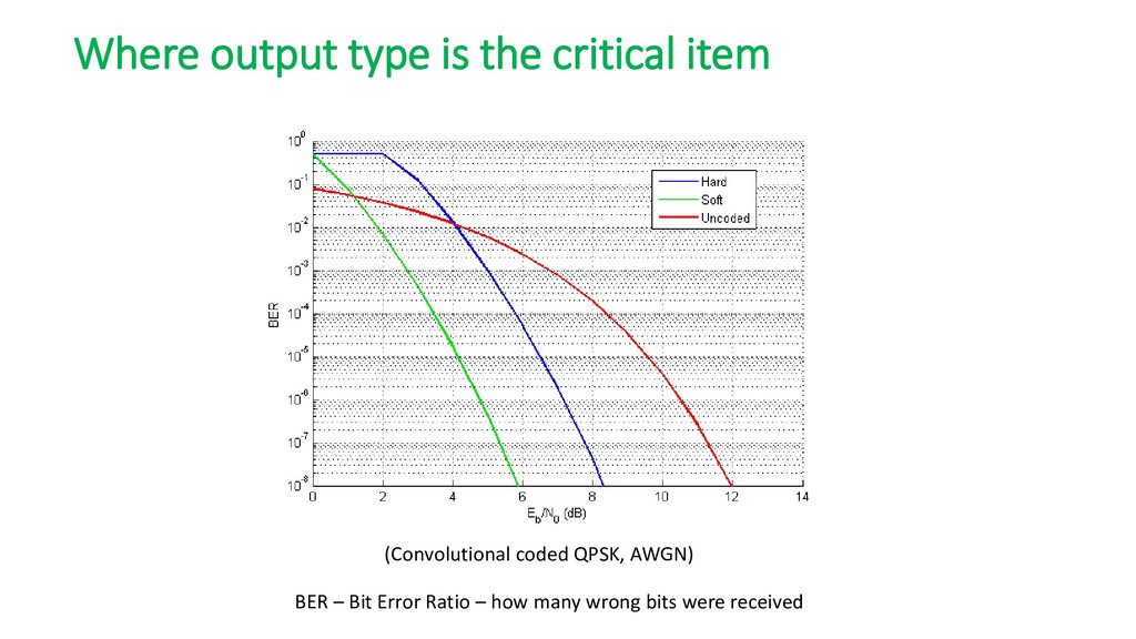
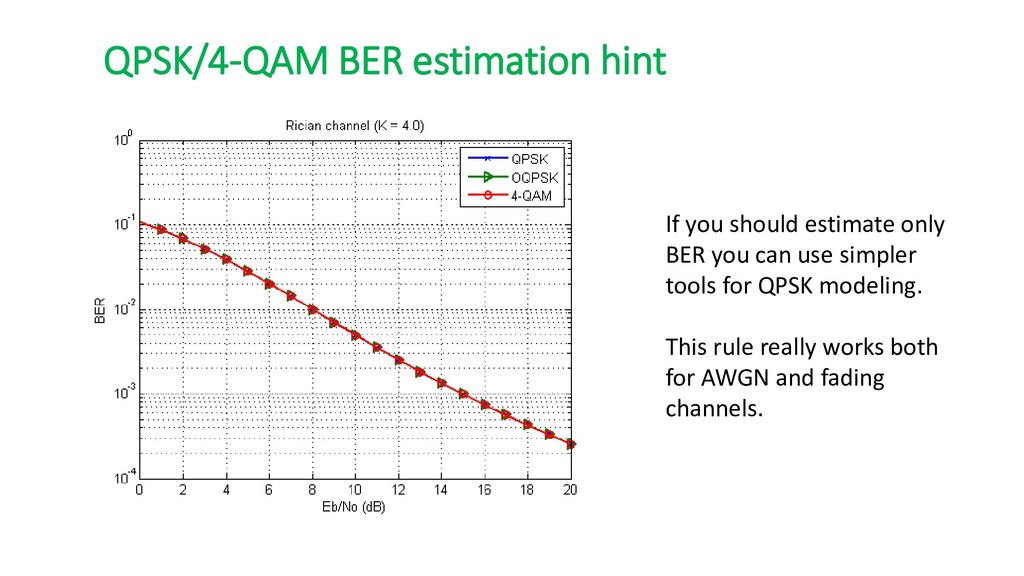
or berawgn() and berfading() to obtain theoretical curves for different modulations. It is a good tool to verify you models. BER – Bit Error Ratio – how many wrong bits were received Actually, BER (or error probability) is the function of the dmin (minimum Euclidean distance) and SNR. See more in Proakis J. G. Digital communications. 1995 //McGraw-Hill, New York. – p. 95-107
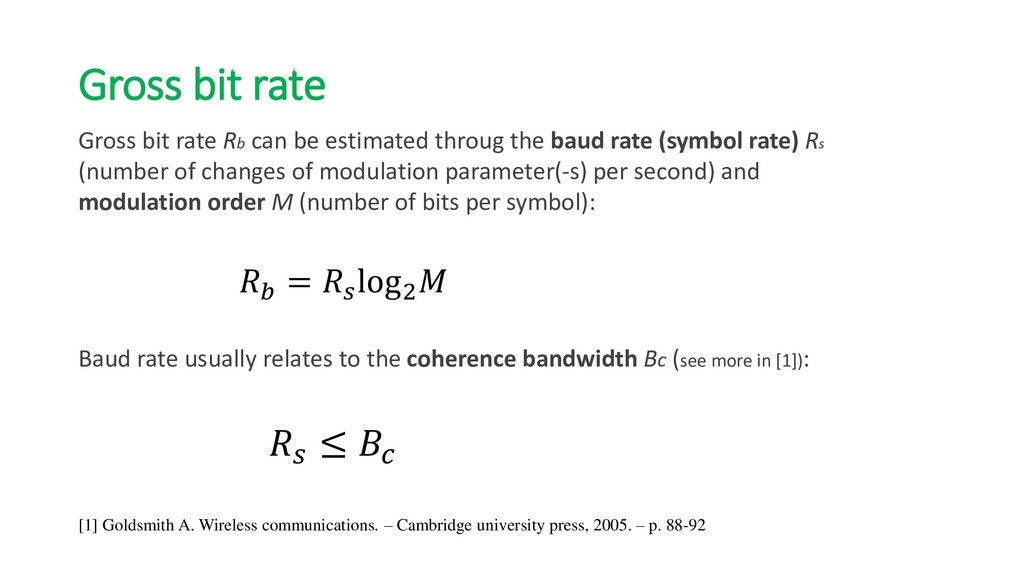
throug the baud rate (symbol rate) Rs (number of changes of modulation parameter(-s) per second) and modulation order M (number of bits per symbol): = log2 Baud rate usually relates to the coherence bandwidth Bc (see more in [1]): ≤ [1] Goldsmith A. Wireless communications. – Cambridge university press, 2005. – p. 88-92
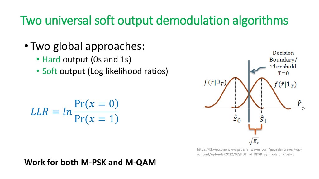
0 ) Pr( = 1 https://i2.wp.com/www.gaussianwaves.com/gaussianwaves/wp- content/uploads/2012/07/PDF_of_BPSK_symbols.png?ssl=1 Work for both M-PSK and M-QAM •Two global approaches: • Hard output (0s and 1s) • Soft output (Log likelihood ratios)
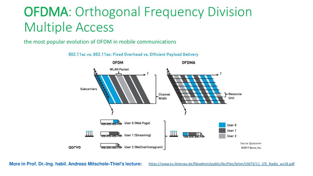
of OFDM in mobile communications https://www.tu-ilmenau.de/fileadmin/public/iks/files/lehre/UMTS/11_LTE_Radio_ws18.pdf More in Prof. Dr.-Ing. habil. Andreas Mitschele-Thiel's lecture:
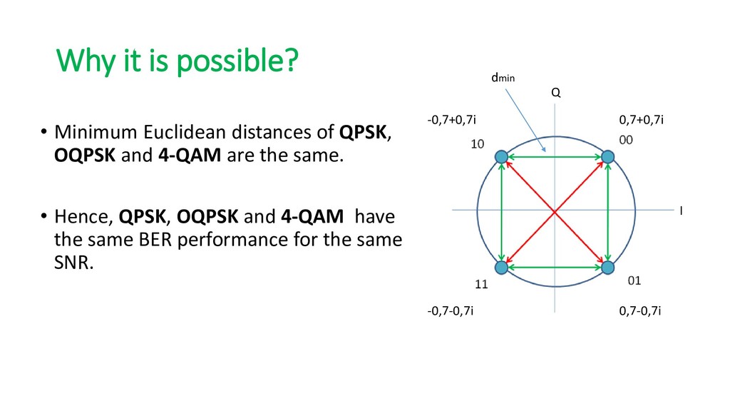
OQPSK and 4-QAM are the same. • Hence, QPSK, OQPSK and 4-QAM have the same BER performance for the same SNR. 0,7+0,7i -0,7+0,7i -0,7-0,7i 0,7-0,7i I Q dmin
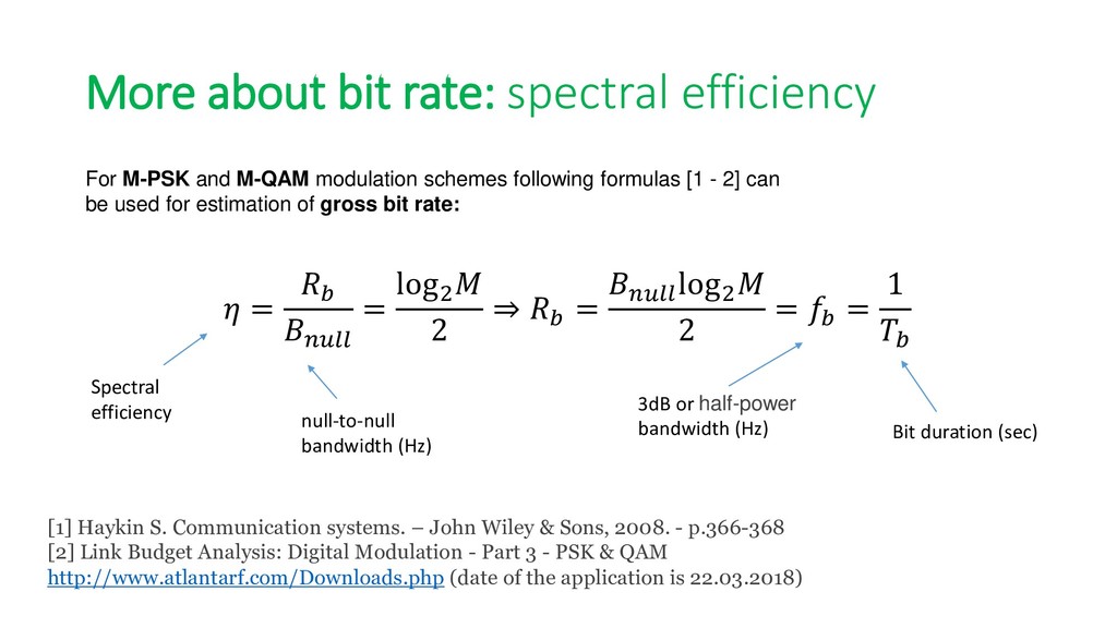
modulation schemes following formulas [1 - 2] can be used for estimation of gross bit rate: Spectral efficiency null-to-null bandwidth (Hz) [1] Haykin S. Communication systems. – John Wiley & Sons, 2008. - p.366-368 [2] Link Budget Analysis: Digital Modulation - Part 3 - PSK & QAM http://www.atlantarf.com/Downloads.php (date of the application is 22.03.2018) = = log2 2 ⇒ = log2 2 = = 1 3dB or half-power bandwidth (Hz) Bit duration (sec)
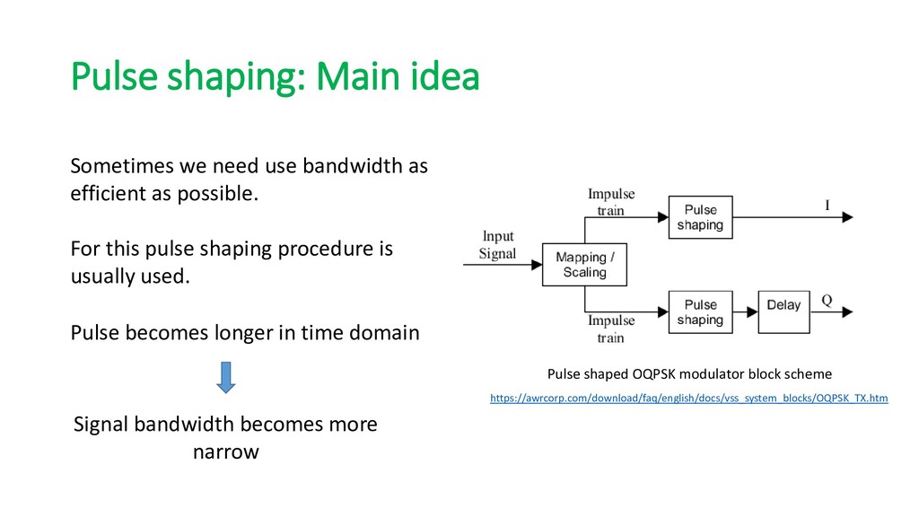
efficient as possible. Pulse becomes longer in time domain Signal bandwidth becomes more narrow Pulse shaped OQPSK modulator block scheme https://awrcorp.com/download/faq/english/docs/vss_system_blocks/OQPSK_TX.htm For this pulse shaping procedure is usually used.
the roll-off factor β we have more compact frequency response (more efficient usage of the spectrum). By Krishnavedala - Own work, CC BY-SA 3.0, https://commons.wikimedia.org/w/index.php?curid=15390895 However, β=0 is the ideal case with difficulties of implementation and synchronization
![Wireless communication basics: Linear modulation schemes M.Sc. Vladimir Fadeev [email protected]](https://files.speakerdeck.com/presentations/64637ccf6a164939a155c72bd2427c72/slide_0.jpg)