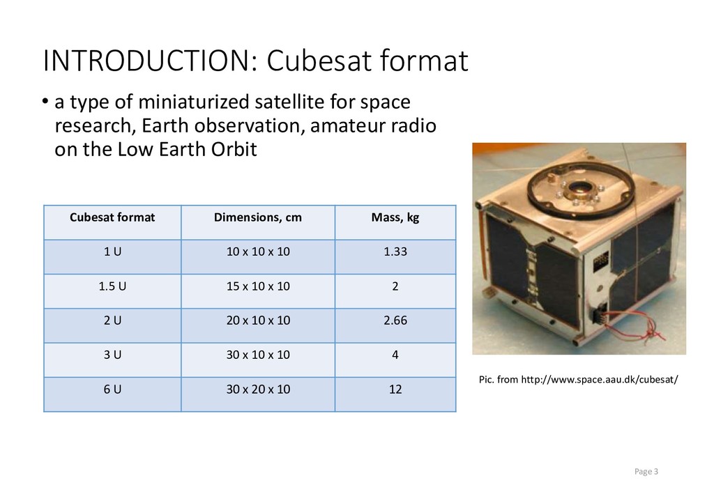
space research, Earth observation, amateur radio on the Low Earth Orbit Page 3 Pic. from http://www.space.aau.dk/cubesat/ Cubesat format Dimensions, cm Mass, kg 1 U 10 x 10 x 10 1.33 1.5 U 15 x 10 x 10 2 2 U 20 x 10 x 10 2.66 3 U 30 x 10 x 10 4 6 U 30 x 20 x 10 12
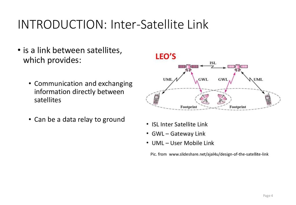
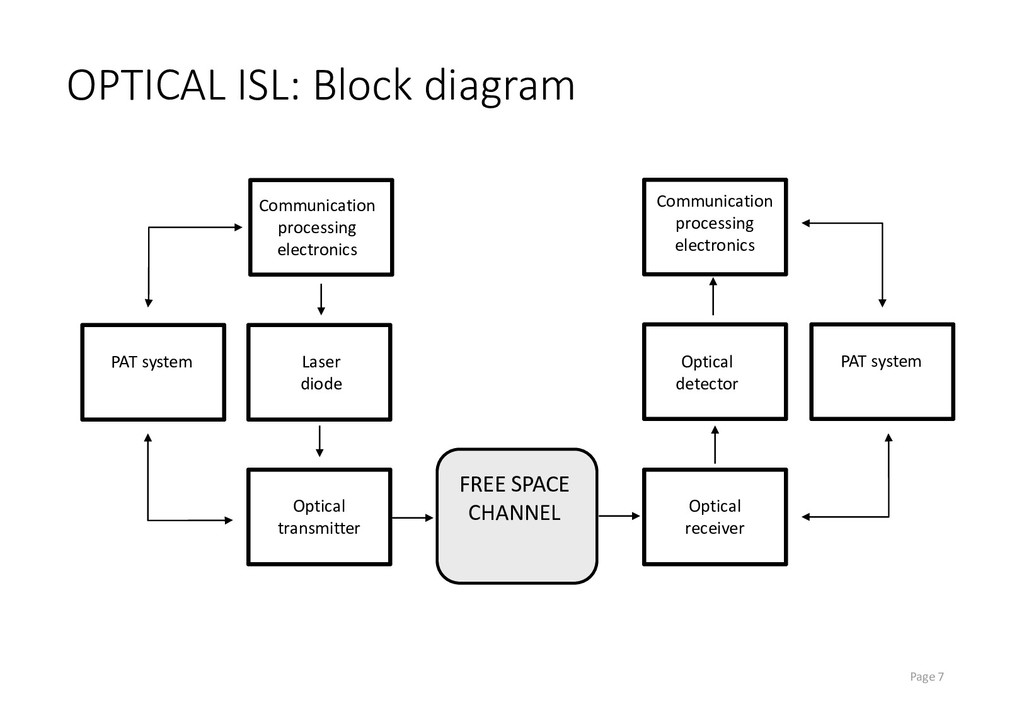
provides: • Communication and exchanging information directly between satellites • Can be a data relay to ground Page 4 Pic. from www.slideshare.net/ajal4u/design-of-the-satellite-link
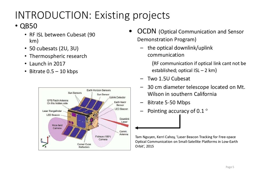
(90 km) • 50 cubesats (2U, 3U) • Thermospheric research • Launch in 2017 • Bitrate 0.5 – 10 kbps Page 5 • OCDN (Optical Communication and Sensor Demonstration Program) – the optical downlink/uplink communication (RF communication if optical link cant not be established; optical ISL – 2 km) – Two 1.5U Cubesat – 30 cm diameter telescope located on Mt. Wilson in southern California – Bitrate 5-50 Mbps – Pointing accuracy of 0.1 Tam Nguyen, Kerri Cahoy, ’Laser Beacon Tracking for Free-space Optical Communication on Small-Satellite Platforms in Low-Earth Orbit’, 2015
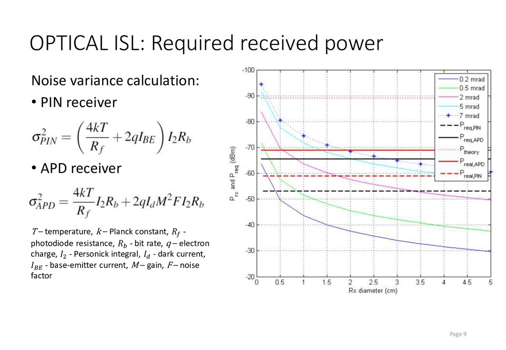
receiver • APD receiver Page 9 T – temperature, k – Planck constant, - photodiode resistance, - bit rate, q – electron charge, 2 - Personick integral, - dark current, - base-emitter current, M – gain, F – noise factor
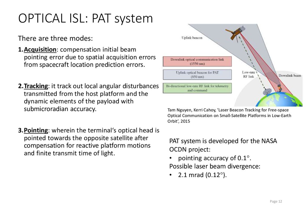
initial beam pointing error due to spatial acquisition errors from spacecraft location prediction errors. 2.Tracking: it track out local angular disturbances transmitted from the host platform and the dynamic elements of the payload with submicroradian accuracy. 3.Pointing: wherein the terminal‘s optical head is pointed towards the opposite satellite after compensation for reactive platform motions and finite transmit time of light. Page 12 PAT system is developed for the NASA OCDN project: • pointing accuracy of 0.1. Possible laser beam divergence: • 2.1 mrad (0.12). Tam Nguyen, Kerri Cahoy, ’Laser Beacon Tracking for Free-space Optical Communication on Small-Satellite Platforms in Low-Earth Orbit’, 2015
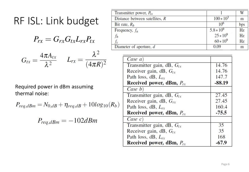
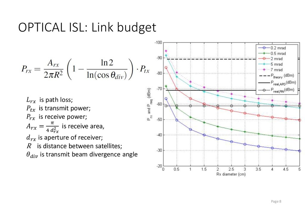
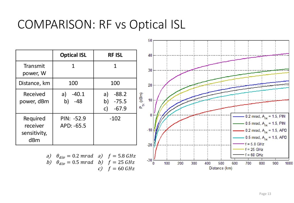
ISL Transmit power, W 1 1 Distance, km 100 100 Received power, dBm a) -40.1 b) -48 a) -88.2 b) -75.5 c) -67.9 Required receiver sensitivity, dBm PIN: -52.9 APD: -65.5 -102 a) = 0.2 b) = 0.5 a) = 5.8 b) = 25 c) = 60
and lower power consumption (in APD case). However, RF case has greater margin and does not require too much precise pointing, acquisition and tracking and can be implemented more easily. RF can be better solution for cubesat ISL, than optical. Page 14