Upgrade to Pro — share decks privately, control downloads, hide ads and more …

My Cisco CCNA notes - May 2011

Avatar for Maechi Maechi
June 27, 2013

My Cisco CCNA notes - May 2011

This is the final edit of my Cisco CCNA notes I put together shortly before taking my exam. It's from 2011 and I've seen a few things that can be updated/corrected, but I decided not to tinker with it and have since moved on to other exams. Putting it together was a very helpful tool for me. Hopefully they turn into a helpful tool for you.

Avatar for Maechi

Maechi

June 27, 2013

Other Decks in Technology

Transcript

  1. PAGE 1 OF 40 CISCO CCNA STUDY NOTES - FINAL.DOC

    PRINTED: 27/06/2013 CCNA 640-802 Notes Layered Communication Terminology Networking Getting information from one point to another in the most effective way. Reference Models > Models describe end-to-end network connectivity specifying how data should be formatted, addressed, transmitted, routed and received at the destination through design guidelines and implementations of specific networking protocols. > Layers are used to divide tasks involved with moving information between networked computers into smaller, more manageable task groups. A task or group of tasks is then assigned to each layers. > Each layer is reasonably self-contained so that the tasks assigned to each layer can be implemented independently. This enables the solutions offered by one layer to be updated without adversely affecting the other layers. DOD TCP/IP Model - Department Of Defense Transfer Control Protocol / Internet Protocol Model > This model was created in the 1970s by DARPA. It evolved from ARPANET, which was the world's first WAN and a predecessor of the Internet. It is currently maintained by the Internet Engineering Task Force (IETF). > This model is composed of four layers, but the layers within this model are not clearly defined. > This model is also called the Internet Model or the Internet Protocol Suite. OSI Model - Open System Interconnect Model > Developed by the International Organization for Standardization (ISO) in 1984. > This model is composed of seven layers and the layers within this model are clearly defined. > The layers can be divided into two categories: the upper 3 application layers and the lower 4 data flow layers. The upper layers are generally implemented only in software and they define how host applications communicate with each other and their users. The lower layers handle data transport issues and they define connection protocols and methods for exchanging data. > It is now considered the primary architectural model for intercomputer communications. Cisco Three-Layer Hierarchy > This is a three layer hierarchical model used to describe how specific network elements fit into the overall network architecture. Its purpose is to provide a balance for the availability, security, flexibility, modularity, resiliency, and manageability required to meet current and future business and technological needs. > The key principle of this hierarchical design is that each element in the hierarchy has a specific set of functions and services that it offers and a specific role to play in each layer of the design. > This model is most often used to defines the physical topology of switches and routers. Protocol > A set of rules that control horizontal communication. > These rules are instructions / procedures that describe communication between different machines on a network. PDU - Protocol Data Unit >The combination of data and a layer-specific header; at Layer 2 a trailer is also added. > A group of information added or removed by a particular layer of the OSI model used to communicate and exchange information. This layer information is used to move data up and down the stack > The communication between layers higher than Layer 1 is logical; the only hardware connection is at the physical layer. Vertical communication > When each layer uses an interface to provide services to the upper adjacent layers and receive services from the lower adjacent layers on the same host. > Encapsulation happens when the PDU information is only added by the peer layer on the sending device and sent down the stack. > Deencapsulation happens when the PDU is read by the peer layer on the receiving device, stripped off, and then sent up the stack. > Also known as encapsulation or adjacent-layer interaction. Horizontal communication > When a layer on one host uses a PDU to communicate to the corresponding layer on another host. > Also known as peer communication or same-layer interaction. DOD Model - Department Of Defense TCP/IP Model Layer Description Examples 4 Application (Process) > Applications create user data and communicate this data to other processes or applications on another or the same host. The communication partners are often called peers. > This layer includes protocols that act like the OSI's presentation and session layer protocols. This is usually done through libraries. HTTP, SMTP, FTP, SSH, etc... 3 Transport (Host-to-Host) > Responsible for the accuracy of end-to-end data transmission, opening and maintaining connections between Internet hosts that hides the physical topology of the underlying network connections. TCP, UDP, SCTP, RTP
  2. PAGE 2 OF 40 CISCO CCNA STUDY NOTES - FINAL.DOC

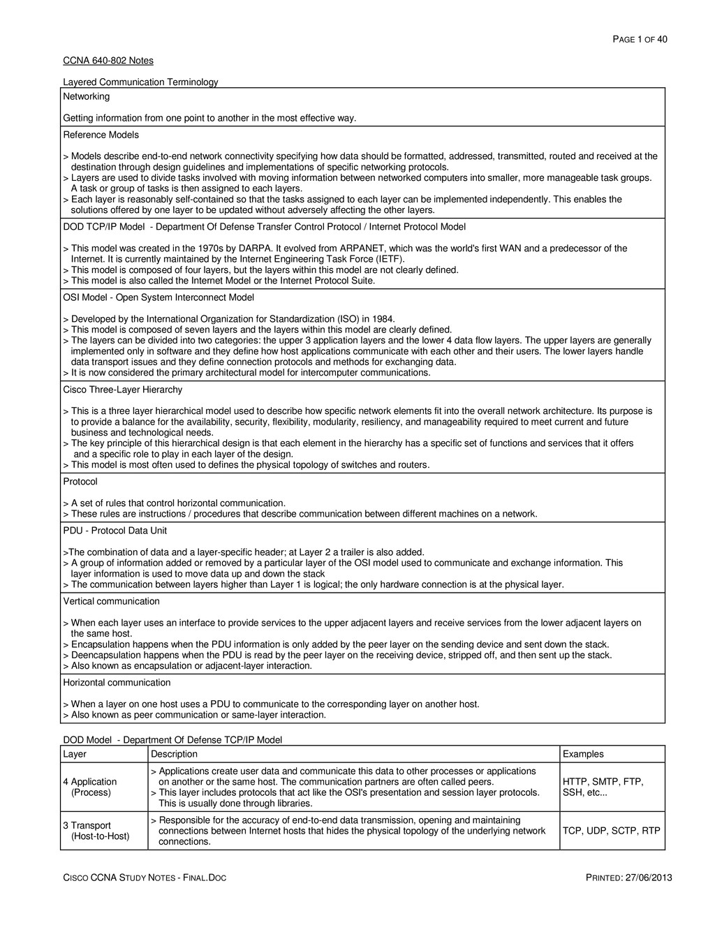
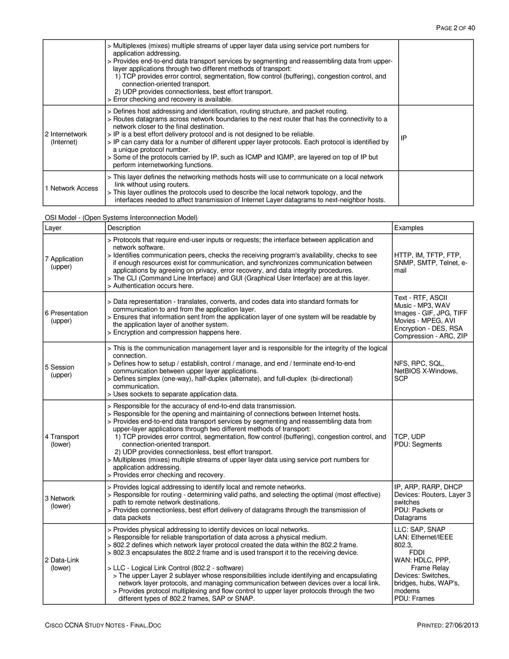
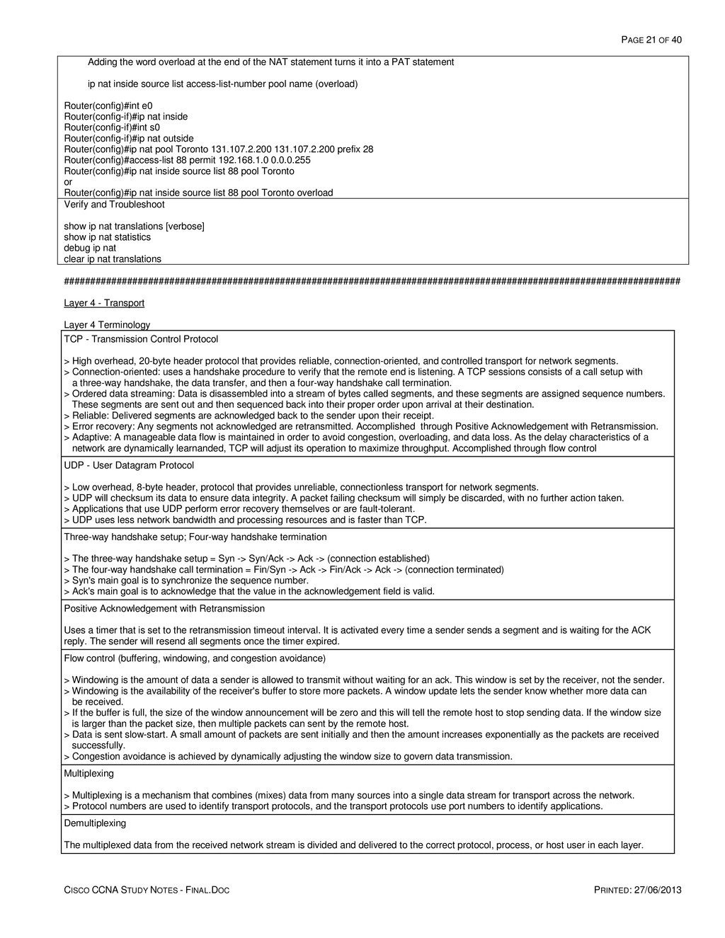
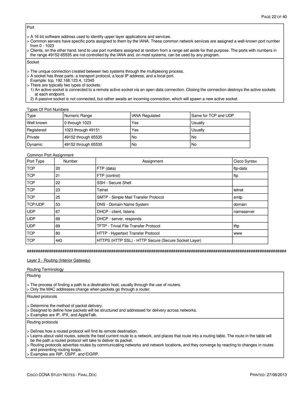
    PRINTED: 27/06/2013 > Multiplexes (mixes) multiple streams of upper layer data using service port numbers for application addressing. > Provides end-to-end data transport services by segmenting and reassembling data from upper- layer applications through two different methods of transport: 1) TCP provides error control, segmentation, flow control (buffering), congestion control, and connection-oriented transport. 2) UDP provides connectionless, best effort transport. > Error checking and recovery is available. 2 Internetwork (Internet) > Defines host addressing and identification, routing structure, and packet routing. > Routes datagrams across network boundaries to the next router that has the connectivity to a network closer to the final destination. > IP is a best effort delivery protocol and is not designed to be reliable. > IP can carry data for a number of different upper layer protocols. Each protocol is identified by a unique protocol number. > Some of the protocols carried by IP, such as ICMP and IGMP, are layered on top of IP but perform internetworking functions. IP 1 Network Access > This layer defines the networking methods hosts will use to communicate on a local network link without using routers. > This layer outlines the protocols used to describe the local network topology, and the interfaces needed to affect transmission of Internet Layer datagrams to next-neighbor hosts. OSI Model - (Open Systems Interconnection Model) Layer Description Examples 7 Application (upper) > Protocols that require end-user inputs or requests; the interface between application and network software. > Identifies communication peers, checks the receiving program's availability, checks to see if enough resources exist for communication, and synchronizes communication between applications by agreeing on privacy, error recovery, and data integrity procedures. > The CLI (Command Line Interface) and GUI (Graphical User Interface) are at this layer. > Authentication occurs here. HTTP, IM, TFTP, FTP, SNMP, SMTP, Telnet, e- mail 6 Presentation (upper) > Data representation - translates, converts, and codes data into standard formats for communication to and from the application layer. > Ensures that information sent from the application layer of one system will be readable by the application layer of another system. > Encryption and compression happens here. Text - RTF, ASCII Music - MP3, WAV Images - GIF, JPG, TIFF Movies - MPEG, AVI Encryption - DES, RSA Compression - ARC, ZIP 5 Session (upper) > This is the communication management layer and is responsible for the integrity of the logical connection. > Defines how to setup / establish, control / manage, and end / terminate end-to-end communication between upper layer applications. > Defines simplex (one-way), half-duplex (alternate), and full-duplex (bi-directional) communication. > Uses sockets to separate application data. NFS, RPC, SQL, NetBIOS X-Windows, SCP 4 Transport (lower) > Responsible for the accuracy of end-to-end data transmission. > Responsible for the opening and maintaining of connections between Internet hosts. > Provides end-to-end data transport services by segmenting and reassembling data from upper-layer applications through two different methods of transport: 1) TCP provides error control, segmentation, flow control (buffering), congestion control, and connection-oriented transport. 2) UDP provides connectionless, best effort transport. > Multiplexes (mixes) multiple streams of upper layer data using service port numbers for application addressing. > Provides error checking and recovery. TCP, UDP PDU: Segments 3 Network (lower) > Provides logical addressing to identify local and remote networks. > Responsible for routing - determining valid paths, and selecting the optimal (most effective) path to remote network destinations. > Provides connectionless, best effort delivery of datagrams through the transmission of data packets IP, ARP, RARP, DHCP Devices: Routers, Layer 3 switches PDU: Packets or Datagrams 2 Data-Link (lower) > Provides physical addressing to identify devices on local networks. > Responsible for reliable transportation of data across a physical medium. > 802.2 defines which network layer protocol created the data within the 802.2 frame. > 802.3 encapsulates the 802.2 frame and is used transport it to the receiving device. > LLC - Logical Link Control (802.2 - software) > The upper Layer 2 sublayer whose responsibilities include identifying and encapsulating network layer protocols, and managing communication between devices over a local link. > Provides protocol multiplexing and flow control to upper layer protocols through the two different types of 802.2 frames, SAP or SNAP. LLC: SAP, SNAP LAN: Ethernet/IEEE 802.3, FDDI WAN: HDLC, PPP, Frame Relay Devices: Switches, bridges, hubs, WAP's, modems PDU: Frames
  3. PAGE 3 OF 40 CISCO CCNA STUDY NOTES - FINAL.DOC

    PRINTED: 27/06/2013 > Allows upper layer protocols to operate independently from the LAN media. > Creates frames from physical layer bits, and bits from frames. > MAC - Media Access Control (802.3 - hardware) > The lower Layer 2 sublayer whose responsibilities include managing protocol access to the physical network medium and managing physical hardware addressing. > Defines adapter interfaces and supported cable types. > Determines who is allowed to access the transmission medium and the appropriate timing to use on the physical media to avoid collisions through CSMA/CD or CSMA/CA. > Provides error detection, but no recovery. > Provides either reliable or unreliable transmission of data across the physical layer media. > Determines the beginning and end of frames. 1 Physical (lower) > Responsible for data transmission - the moving of bits between devices. > Defines the physical characteristics of the transmission medium such as physical connectors, physical data rates, maximum transmission distances, voltage levels, and clocking (timing). LAN: Cat5, Cat6 WAN: V.35, EIA/TIA-232, EIA/TIA-449 PDU: Bits DOD TCP/IP Model Vs. OSI Model DOD TCP/IP OSI Application (Process) Application / Presentation / Session Transport (Host-to-Host) Transport Internetwork (Internet) Network Network Access Data Link / Physical Cisco Three-Layer Model Layer Network Device Core (Backbone) > Responsible for high speed switching and transporting large amounts of network traffic both reliably and quickly. If there is a failure in the core, every single user can be affected. > Should be designed for speed, low latency, low convergence, high reliability, redundancy, and fault tolerance. No packet manipulation should happen at this level. High Speed Routers, Multi- layer switches. Distribution (Routing) > Sometimes known as the workgroup layer. It primarily functions to provide routing, filtering, and WAN access. > The distribution layer is the place to implement: 1) The definition, containment, and control of broadcast and multicast domains. 2) Media translation, packet manipulation, and frame conversion between LAN and WAN. 3) Path determination and redistribution between routing protocols through dynamic and static routing. 4) VLAN management and inter-VLAN routing. 5) Security and network policies to include access lists, address translations, and firewalls. Layer 3 switches, Routers. Access (Switching) > The initial entry point for workstations, nodes, and other user devices. > Performs MAC layer filtering, VLAN membership, and collision domain management. Switches, bridges, hubs. ##################################################################################################################### Basic Switch and Router Operation Layer 3 Routers > Responsible for locating and selecting paths to remote networks. > Routers perform packet switching, packet filtering, internetwork communication, and path selection. > They maintain the most up-to-date routing information and can provide multiple paths to a destination network. > Routers filter or forward packets based on Layer 3 (IP address) information. > Routers can use routed protocols to create a hierarchical network that supports thousands of devices. > Routers learn about the other routers it is connected to and they learn the network destinations the other routers know about. > Routers will drop any packet it does not have a path for in its routing table; a packet it does not know how to forward on to its final destination. This is different from a switch, which will flood its frame when the frame's destination is unknown. > Routers contain multicasts and broadcasts - these packets are dropped and not forwarded. > This layer allows for different media types to be connected together, like Ethernet, PPP, and others. > Each port on a router is a collision domain and a broadcast domain. Each port will break up a Layer 2 collision domain and break up a Layer 3 broadcast domains. Layer 2 Bridges, Switches
  4. PAGE 4 OF 40 CISCO CCNA STUDY NOTES - FINAL.DOC

    PRINTED: 27/06/2013 > Responsible for locating and managing specific hosts within a local network segment. > Switches optimize network performance by breaking up collision domains and providing more bandwidth to LAN users. > There are three main aspects to a switch: 1) They learn MAC addresses from the source field on frame headers. 2) They filter or forward frames based on Layer 2 (MAC address) information. 3) They provide loop avoidance through STP. > When the device is first powered on, its MAC address table is empty. This forces the device to flood any frames it receives out of every port (or through each port within a VLAN) except the originating port until it is able to create its MAC address table. > Switches flood unknown, broadcast, and multicast frames through each port within a VLAN except the originating port. This is different from a router which drops unknown packets. > Switches support full duplex communication. > Bridges learn, forward, and remove routing loops. They are software based, relatively slow, usually have one STP per bridge, and typically have up to 16 ports. > Switches are advanced multiport bridges that are hardware based, use port-level ASIC's (Application-Specific Integrated Circuit), are relatively fast operating at wirespeed, can support more than one instance of STP, and can have hundreds of ports. > Each port on a switch is a collision domain. Each port will break up a Layer 2 collision domain, but they cannot break up Layer 3 broadcast domains. Layer 1 Hubs, Repeaters > Hubs are used to connect multiple users to a single physical device and a single physical bus. > These devices also act as repeaters by regenerating the signals that passes through them. > They connect network segments together to extend collision and broadcast domains. > They do not perform any address recognition functionality. > They do not break up collision or broadcast domains. General Switch and Router Terminology Collision When data signals from two or more hosts, using one common signal wire, are sent at the same time and meet each other. Collision domain > Same physical segment. > A frame sent by one host could result in a collision with a frame sent by another host on the same link (same bus). Broadcast > A transmission sent to all nodes on a collision domain (link-local segment). > Addresses are all 1's in binary, or ff:ff:ff:ff:ff:ff in hex. > This frame does not go beyond the router. Broadcast domain > Same logical segment. > A broadcast frame sent by one host is received by all other hosts within the same domain. Interface A physical connection to a network. Also called a jack or port. Subinterface > A virtual interface that is a logical division of a physical interface. > Once created, a router will treat a subinterface like a physical interface. Loopback interface > A logical, virtual interface created on a router. > These interfaces are treated as physical interfaces on a router, but they do not go down like a physical interface. They are always reachable as long as one physical interface is available on the router. > You can create as many of these interfaces as you need from port numbers 0 to 2147483647. > You can assign addressing information to them, include their network numbers in routing updates, and even terminate IP connections on them. Dynamic MAC address A MAC address learned by the switch from the source address field of a frame. Static MAC Address A MAC address configured by an administrator. Permanent MAC Address A MAC address assigned to a specific port by an administrator.
  5. PAGE 5 OF 40 CISCO CCNA STUDY NOTES - FINAL.DOC

    PRINTED: 27/06/2013 IOS - Internetwork Operating System > The IOS is stored in Flash memory and is a multitasking operating system packaged with routing, switching, internetworking, and telecommunication functions. Configuration Register > The configuration register is used to control the startup behavior of a device and is stored in NVRAM. > It is 16 bits (2 bytes) long with the four least-significant bits making up the boot field. > Its uses include: 1) Recover a lost password 2) Define boot sources for the default IOS software 3) Force an automatic boot using a boot image 4) Define a default boot filename 5) Enable/disable the Break function 6) Control broadcast address 7) Set the console terminal baud rate (console speed) Switch Port Light Status Light Description Off No link or the port is administratively shutdown. Green The port is on and a link is present. Blinking Green There is activity on the link - the port is sending or receiving data. Alternating Green-Amber There is a fault detected on the link. It could be excessive collisions, CRC, alignment, or jabber errors. Solid Amber The port is disabled by Spanning Tree Protocol, management, or an address violation and is not forwarding data. General Switch and Router Device Memory (in the order accessed after power is applied) ROM > ROM stores a limited-function IOS System Bootstrap image called RxBoot (newer systems no longer have RxBoot). > ROM also stores the bootstrap program called ROM Monitor (ROMMON). ROMMON allows you to boot the router when flash memory does not contain a valid system image. > It also allows for low-level debugging (CISCO TAC) and password recovery. Flash and PCMCIA CompactFlash > Flash is an internal EEPROM chip that stores a copy of the full IOS image. > Flash can also be used to store any other binary files when a router is configured as a TFTP server. > VTP information saved in the VLAN.DAT file is also stored here. > PCMCIA is like Flash in operation, but it is an external CompactFlash card. > If the Flash is corrupted and no TFTP server is available, then the device will boot from ROM. NVRAM > The startup configuration file is stored here. > The 16-bit configuration register is stored here. > If there is no startup configuration file available, the device will enter Setup mode. RAM (DRAM - Dynamic Random Access Memory) > This is the working storage memory, the operating environment. > The running (active) configuration file and the routing tables are stored here. > This is the only volatile (non-permanent) memory. > Cisco partitions its RAM memory. To find out the total amount of DRAM, add the DRAM and Packet memory portion. Switch Transmission Modes Store-and-forward > Complete frames are received and the CRC is checked. Runts (frames < 64 bytes) or giants (frames > 1518 bytes) are discarded. > For normal frames, the relevant filters are applied and then the frame is forwarded. > This is the default setting between ports of different speeds. > High latency Fragment-free (Cisco) > The first 64 bytes (minimum Ethernet frame size) is read. > Fragmented frames (frames that experience collisions within the first 64 bytes) are discarded. > Low latency Cut-through
  6. PAGE 6 OF 40 CISCO CCNA STUDY NOTES - FINAL.DOC

    PRINTED: 27/06/2013 > The packet is forwarded as soon as the destination address (6 bytes) is known. > Lowest latency General Switch and Router User Mode Access Methods Console > Console is the local, on-site, physical access to a device. This is done through a console cable (rollover cable) from a serial connection on a host system to the console port on the device. > The pins on a console cable are reverse-mirrored so that 1 on one end is 8 on the other, 2 on one end is 7 on the other, and so forth. > Use a terminal emulator program to connect to the device through the console port at these settings: 1) 9600bps 2) 8 data bits 3) No parity 4) 1 stop bit 5) No flow control settings. Telnet This is a connectivity utility. A simple remote terminal emulation application by which one host can connect and run a session on another host. Aux This connection is typically used as a backup connection to access the device through a modem. General Switch and Router Operating Modes Mode Prompt Description ROM Monitor > [or] rommon#> > When no IOS is present or it is invalid. > When the boot sequence is interrupted. > Also used for password recovery RXBoot Router<boot> > Helper software that helps the router boot with it cannot find the IOS image in flash. > Boot using config register 0x2101 Setup > Basic setup configures just enough connectivity for system management. > Extended setup provides for more configuration options like both enable passwords. > Setup mode comes when no config file is available or by entering in the [setup] command. Exit setup mode with ctrl-c User Device> > Read-only privileges. > Limited ability to examine device information and status. Privileged (Exec) Device# > Full privilege to read, write, modify, copy, and delete files. > Examine device status and configuration files. > Ability to change IOS and configuration file. > Also known as privileged exec mode and enabled mode. Global configuration Device(config)# Modify the running (active) configuration to configure the whole device. Sub-configuration Device(config-if)# Device(config-subif)# Device(config-line)# Device(config-router)# Device(config-std-nacl)# Configure individual interfaces. Configure virtual interfaces (sub-interfaces) Configure individual terminal lines (access interfaces) Configure routing protocols Configure named access lists Interface Naming Convention Interface Description interface ethernet 0/1 interface ethernet 0 1 interface type interface-type (chassis slot) # port (interface) # interface ethernet 2/0/1 interface ethernet 2 0 1 interface type interface-type (chassis slot) # slot (port adapter) # port (interface) # IOS Naming Convention Example: c3725-entbase-mz.124-6.bin c3725 entbase m z 12 4 6 bin Platform features set memory location compression format major release minor release revision number file type Memory location f — The image runs from Flash memory. m — The image runs from RAM. r — The image runs from ROM. l — The image is relocatable.
  7. PAGE 7 OF 40 CISCO CCNA STUDY NOTES - FINAL.DOC

    PRINTED: 27/06/2013 Compression format z — The image is zip compressed. x — The image is mzip compressed. File type .bin — binary Cisco IOS Packaging Advanced Enterprise Services (Full Cisco IOS Software) Advanced IP Services (Merge Advanced Security & SP Services, IPv6) Enterprise Services or Enterprise Services w/o Crypto (Merge Enterprise Base & SP Services) Advanced Security (Add Sec/VPN to Data) Cisco IOS FW, IDS/IPS, NAC, SSH/SSL, IPSec, etc. SP Services (Add SP Services to Voice and Data) SSH/SSL, ATM, VoATM, MPLS, etc. Enterprise Base or Enterprise Base w/o Crypto (Add Multiprotocol Services to Data) Enterprise Layer 3 Routed Protocols IP Voice or IP Voice w/o Crypto (Add Voice to Data) VoIP and VoFR IP Base or IP Base w/o Crypto Entry Level Cisco IOS Software Image (Classic IP Data + Trunking and DSL) ##################################################################################################################### Layer 2 - Data Link General Layer 2 Terminology ARP - Address Resolution Protocol > Resolves IP address to MAC address by using a local broadcast to find devices. ARP is sent out as a L2 broadcast, received as a unicast. > Determines the Layer 2 MAC address of a known Layer 3 IP address; maps a known Layer 3 address to an unknown Layer 2 address. RARP - Reverse ARP > Resolves MAC address to IP address. > Determines the Layer 3 IP address of a known Layer 2 MAC address; maps a known Layer 2 address to an unknown Layer 3 address. > Used by BootP and DHCP. Half-Duplex > Can send and receive data, but cannot do both functions at the same time. Devices use the same pair of wires to transmit and receive. This provides for communication in both directions, but for only one direction at a time. > Only possible to use 50% of the available bandwidth. > Uses CSMA/CD. Full-Duplex > Can send and receive data at the same time. Devices use two pairs of wires to communicate, one pair for sending and the other for receiving. This providing for simultaneous communication in both directions. > Can only be configured on point-to-point stations such as pc/server to switch or router to switch because it needs two pairs of wires, full duplex NIC's, and full duplex switch ports to work. > Communication is more efficient than half-duplex: 1) There is no wasted communication time since nodes do not have to wait for other nodes complete their transmission. There is only one transmitter for each twisted pair so no frame needs to be retransmitted as there are no collisions. 2) Full data capacity is available in both directions because the send and receive functions are separated. Duplex mismatch > Results from improper configuration or when the autonegotiation process fails with half-duplex configured on one side and full-duplex on the other. The half-duplex side senses continuous collisions whenever the full-duplex side tries to communicate. > The half duplex side goes through its collision detection procedure until it eventually is able to retransmit. Because of the wait times, this link will work but contention will cause it to be very slow. MAC Address (physical address) > This is the network interface address. > It is a 48 bit (6 byte) address. It is written on hexadecimal notation with a colon separating each byte. > A MAC address is the combination of the 3 byte OUI and a three byte vendor assigned address (16 million addresses are possible). OUI - Organizational Unique Identifier > The OUI is the first three bytes (24 bits) of a MAC address that is purchased from and assigned by the IEEE. > It is globally unique and it identifies the assignee that purchased it. Frame
  8. PAGE 8 OF 40 CISCO CCNA STUDY NOTES - FINAL.DOC

    PRINTED: 27/06/2013 > A Frame is (usually) a stream of serial bits transmitted at the physical layer that often contain a header field at the beginning and a trailer field at the end that "frame" the data being sent. > The organization of the information in a frame is protocol-dependent; that is, the contents and organization of a frame depends upon which data-link layer network protocol is transmitting the frame. > Frames generated by different protocols are not compatible and cannot be used together on the same physical network segment. Layer 2 multicast (hardware multicast) > Ethernet uses the low-order bit of the high-order octet to distinguish conventional unicast addresses from multicast addresses. A unicast would have this bit set to ZERO (0), whereas a multicast would have this bit set to ONE (1). > Multicast MAC addresses start with 01:00:5e; the address range of the second half fall within 00:00:00 - 7f:ff:ff Example: unicast = 00:11:22:aa:bb:cc multicast = 01:00:5E:00:00:05 0000 0001 0000 0000 0101 1110 Ethernet > There are two versions of Ethernet: IEEE and DIX (Digital, Intel, & Xerox). DIX evolved over time and its current version is called Ethernet II. > The IEEE version is standardized in the 802.2 and 802.3 standards. SAP - Service Access Point > A method for multiplexing protocols. > Can only accommodate 64 numbers and they are assigned to international (public) standards. IP is not one of these standards. SNAP - SubNetwork Access Protocol > A method for multiplexing more protocols than SAP. It is included in an extension of the 802.2 LLC header. > Supports SAP (public protocols) and private protocols. > The SNAP header follows the 802.2 header. It has a 5-octet protocol ID field, consisting of a 3 byte IEEE OUI followed by a 2 byte protocol ID. CSMA/CD - Carrier Sense Multiple Access / Collision Detection (Wired Ethernet contention method) 1) The NIC senses the bus, if it is free it sends the frame. 2) If a collision occurs, a 32-bit jam signal is sent out along the bus. 3) When that signal is received, all nodes run a back off algorithm. 4) After each node has run its algorithm, it tries to retransmit starting at item 1. 5) The back off algorithm will occur fifteen more times if necessary (for a total of 16) before it determines that the frame is undeliverable and sends it back up the stack as undeliverable. VLAN - Virtual Local Area Network VLAN Terminology LAN - Local Area Network All devices within the same broadcast domain. VLAN - Virtual LAN > A Layer 2 concept that logically divides a switch into multiple broadcast domains that can span multiple physical LAN segments through trunks. Creating multiple VLAN's will increase the number of broadcast domains while decreasing the size of each domain. > Ports on a switch in the same VLAN are a part of the same subnet and use the same IP address space. > Traffic between VLAN's must be routed through a Layer-3 device. > A separate STP bridging table is maintained for each VLAN. Access Mode > A port that belong to a single assigned VLAN and does not provide any identifying marks on the frames that are passed between switches. > It only carries traffic from the VLAN it is assigned to. Trunk Mode > Trunks pass VLAN information between switches. They allow frames from multiple VLAN's to pass over a single physical connection. > By default, all defined VLAN's are alowed across the trunk. > Trunks mark frames with special tags to distinguish between the traffic flows; both switches must be configured for the same tagging mechanism (ISL or 802.1Q). VTP - VLAN Trunking Protocol > A Layer 2 protocol that maintains constant VLAN configuration across switches. > All switches in a VTP domain must run the same VTP version. > VTP advertisements are sent through trunked ports as multicast frames with a higher revision number every 5 minutes or when there is a change. > Higher revision numbers indicate a more current configuration.
  9. PAGE 9 OF 40 CISCO CCNA STUDY NOTES - FINAL.DOC

    PRINTED: 27/06/2013 VTP V2 > Transparent mode will allow received updates to pass through it onto other switches in the network; instead of discarding them as VTP V1 would do if the domain and password did not match. > Switches must be configured to use the same VTP version to communicate with each other. VTP V3 VTP V3 provides the following enhancements to previous VTP versions: > Support for extended VLANs. > Support for the creation and advertising of private VLANs. > Improved server authentication. > Protection from the "wrong" database accidentally being inserted into a VTP domain. > Interaction with VTP V1 and VTP V2. > Provides the ability to be configured on a per-port basis. > Provides the ability to propagate the VLAN database and other databases. VTP pruning > VTP pruning preserves bandwidth by reducing unnecessary broadcast and multicast traffic over a trunk. > Broadcasts and unknown unicasts are flooded out all trunks in each active VLAN, as long as it is not blocked by STP topology. Enabling pruning allows the switches to intelligently and dynamically determine which switches do not need the frame. > Pruning is disabled by default and can only be enabled on VTP servers or transparent switches. > VLAN1 is the administrative VLAN, and it is not pruned. Only VLAN's 2-1005 are pruning eligible. VTP password > Setting up a VTP password sets the VTP management domain to secure mode. > All switches in the domain must use the same VTP version and have the same password. > The password is used by the switches to authenticate the VTP advertisements received from other switches. VLAN Tagging Identification Methods ISL - Inter Switch Link > Cisco proprietary. > Fully encapsulates the whole Ethernet frame with a 26 byte header and 4 byte CRC trailer. ISL trunking header Field ISL Header Encapsulated Ethernet Frame CRC Bytes 26 Variable 4 802.1q > IEEE standard trunking protocol. > Adds an extra 4-byte header in the middle of the original Ethernet header, forcing a recalculation of the FCS. > 802.1q frames are up to 1522 bytes, They can be larger than the maximum 1518 bytes Ethernet standard length. > Defines a native VLAN. None of the frames are tagged on the native VLAN. The default VLAN ID is 1. 802.1q trunking header | DMAC | SMAC | Len/EType | data | FCS | Original Segment frame | | |\ \ \ \ | | | \----\ \---\ \---\ \--\ | DMAC | SMAC | TAG | Len/Type | data | FCS\ Tagged frame with recalculated FCS. FCS is recalculated because of the inserted TAG. Similarities between ISL and 802.1q > Both ISL and 802.1q allow for a 12-bit long VLAN ID field (4,096 VLAN's; minus two reserved 0 & 4095) > Both support a separate instance of STP for each VLAN. > Normal range = VLAN ID's 1-1005 > Extended range = VLAN's ID's 1006 - 4094 > Five nondeletable VLANS = 1, 1002-1005 VTP Modes Server > Can create, delete, and modify VLAN's. > Originates and forwards VTP advertisements. > Processes received advertisements and synchronizes VLAN info with other switches. > Any changes made affect all downstream client switches in the same VTP domain. > Changes made increment the revision number up; the higher the number the newer the configuration. > Configurations are saved in NVRAM. Client > Cannot create, delete, or modify VLAN's
  10. PAGE 10 OF 40 CISCO CCNA STUDY NOTES - FINAL.DOC

    PRINTED: 27/06/2013 > Forwards VTP advertisements to other devices. > Processes received advertisements and synchronizes VLAN info with other switches. > Configurations are not saved in NVRAM, they are saved in RAM. Transparent > Can create, delete, and modify VLAN's. > Any changes made only affects that one switch. > Revision number in this mode is always 0. > Forwards received VTP advertisements, VTP V2 and up. > Can use extended range 1006-4095 VLAN's > Configurations are saved in NVRAM. > All VLAN information is locally significant and is not broadcasted out. STP - Spanning Tree Protocol & RSTP - Rapid Spanning Tree Protocol Redundant Link Problems Routing loops (Redundant topology) Unknown frames are flooded out all ports. If there are multiple paths, then a flood would go out all ports except the originator, and come back in on the other ports creating a routing loop. Broadcast storms When packets are continuously forwarded around a network, grinding the network to a halt. Multiple frame transmission (MAC database instability) Looping frames are received on different ports causing multiple copies of the same frame to be received by a host. This causes incorrect (duplicate) entries in the MAC database table. STP & RSTP Terminology STP - Spanning Tree Protocol (802.1d) > Designed to prevent Layer 2 switching loops by creating and maintaining a loop-free network topology via a single active logical path. > It cannot prevent broadcast storms or routing loops, it only prevents switching loops. > It is enabled by default, and is configured for each VLAN. > STP is passive, only waiting on BPDU's before reacting. Total convergence time from blocking to forwarding state = 50 seconds. RSTP - Rapid STP (802.1w) > Provides rapid convergence following a change in network topology through technologies like PortFast, UplinkFast, and BackboneFast. > RSTP actively works to discover a network's state > Convergence times are between 1 and 10 seconds. Convergence > The time between a break in the topology occurring and STP's ability to calculate an alternate path. > Convergence is achieved when STP has finished calculating the status of all ports, and has decided whether they will be in forwarding or blocking mode. BPDU - Bridge Protocol Data Unit (Hello Message) BPDU's are special data frames used to exchange information about bridge IDs, root ID's, and root path costs. Hello time > The hello time is the amount of time the root will wait before sending out its periodic Hello BPDU messages. > The default time value is 2 seconds MaxAge > The amount of time a switch will wait, from the time it stops receiving BPDU's, before trying to change its STP topology. > The default time value is 20 seconds; 10x the hello time. Forward delay > The forward delay is the amount of time a switch takes moving between its transitory STP states. > The default time value is 15 seconds Root Bridge > The root bridge is the switch with the lowest bridge ID. It becomes the central point of the STP management process, but not all network traffic. > It is the only switch allowed to send BPDU's. > All of the links on the root bridge are unblocked. They are all designated ports set to Forwarding. > Three way to determine if a switch is the root:
  11. PAGE 11 OF 40 CISCO CCNA STUDY NOTES - FINAL.DOC

    PRINTED: 27/06/2013 1) The root switch will have a message stating so. 2) The root ID MAC will be the same as the bridge ID MAC. 3) All root ports will be in forwarding mode. Bridge ID > The bridge ID is 8 bytes long. It is the combination of a 2 byte bridge priority and the 6 byte MAC address of the switch. > The bridge priority value range is from 0 - 65535. The default value of the bridge priority is 32768. > The bridge priority can be modified by an administrator. The lower the value, the higher the priority. Root port The port that receives the best BPDU on a bridge is the root port. This is the port that is the closest to the root bridge in terms of path cost. Designated Port > A port that can send the best BPDU on the segment to which it is connected. > On a given segment, there can only be one path toward the root bridge. All bridges connected to a given segment listen to the BPDUs of each and agree on the bridge that sends the best BPDU as the designated bridge for the segment. The port on that bridge that corresponds is the designated port for that segment. Blocked Port > A port that is not the designated or the root port. A blocked port receives a more useful BPDU than the one it sends out on its segment. A port must receive BPDUs in order to stay blocked. > There are two types of blocked ports, alternate and backup. Alternate port This is a blocked port that receives more useful BPDUs from another bridge. It provides an alternate path to the root bridge and therefore can replace the root port if it fails. Backup Port > A blocked port that provides redundant connectivity to the same segment and cannot guarantee an alternate connectivity to the root bridge. > It is excluded from the uplink group. Edge Port > The edge port basically corresponds to the PortFast feature. The edge port directly transitions to the forwarding state, and skips the listening and learning stages because directly connected end stations cannot create bridging loops in the network. > Neither edge ports or PortFast enabled ports generate topology change notifications when the link toggles. > An edge port that receives a BPDU immediately loses edge port status and becomes a normal spanning tree port. Link Type > The link type is automatically derived from the duplex mode of a port, or can be manually set by an administrator. > A port that operates in full-duplex is assumed to be point-to-point, while a half-duplex port is considered as a shared port by default. > RSTP can only achieve rapid transition to the forwarding state on edge ports and on point-to-point links. Portfast > This configures the port to go straight into forwarding, skipping the listening and learning modes of STP. > STP still runs on ports with portfast. > The switch never generates a TCN when a port configured for portfast goes up or down. > Use portfast on ports where the connected hosts are very likely to bring their link up and down, typically end-stations. This feature should not be necessary for server ports and it should definitely be avoided on ports that lead to hubs or other bridges. BPDU Guard > When globally enabled, BPDU port-guard and BPDU filtering apply only to portfast enabled ports. > When a BPDU is received on a BPDU port-guard enabled port, the interface goes into the err-disabled state and must be enabled by an administrator to ensure that a switching loop will not occur. UplinkFast Allows for a backup uplink (alt) to immediately change its state from blocked to forward when it detects that an existing local root port has failed. BackboneFast > Similar to UplinkFast, in which a redundant link transitions faster than normal to a forwarding state. The difference is that the transition occurs without having direct knowledge of the link failure. > If an access switch still has connectivity to its root bridge, it will categorize any other BPDU received from a different switch claiming to be a new root as inferior. > The access layer switch bypasses the max age time and immediately transitions from blocking to listening. After the distribution switch receives that BPDU from the access layer switch, it realizes it has a path to the root bridge through the access layer switch, and that corresponding interface becomes its root port.
  12. PAGE 12 OF 40 CISCO CCNA STUDY NOTES - FINAL.DOC

    PRINTED: 27/06/2013 Etherchannel > Etherchannel is the ability to combine multiple (up to eight) parallel segments of equal speeds together and use them as one logical link instead of having them shut down by STP. > Reasons for etherchannel: 1) Bandwidth is not limited to one link. Bandwidth is increased to the sum of all the included links. 2) Link redundancy Four Elements To STP & RSTP Element STP & RSTP State Description Root switch ports Forwarding There is one root switch per broadcast domain, all ports are set to designated. Non-root switch root port Forwarding There is one root port per non-root bridge. LAN's designated port Forwarding The port of the designated switch that connects to that LAN segment must be placed in forwarding mode All other ports Blocked No BPDU's received or forwarded. STP Operation 1) Every new switch added to a network thinks it is the root, and thus sends out BDPU's. 2) After this round of BPDU's are sent, the switch becomes aware whether or not it is the root and acts accordingly. 3) If there are multiple BPDU's received by a switch, there must be a loop. 4) On a non-root switch, the goal is to find the most efficient path back to the root. The port that receives the lowest cost BPDU will be designated the root port. 5) Ports that are not the most efficient path to the root, and are not needed to reach any other downstream switch, are blocked. Blocked ports still receive BPDU's. 6) STP operates passively. A non-root bridge will only generates BPDUs when it receives one on the root port. 7) If the primary path ceases to receive BPDU's, STP will eventually forward packets to an alternate port. Blocked ports are re-evaluated to find the most efficient route back to the root, and then that port is then unblocked. STP Convergence 1) The root port on a non-root switch must cease to receive root BPDU's for MaxAge seconds before it can begin transitioning. (BPDU not heard for 10 Hello times = 20 seconds) 2) The port then goes through a Forward Delay period in the Listening state (15 seconds) 3) The port then goes through another Forward Delay period in the Learning state (15 seconds) 4) The port then goes into the Forwarding state. RSTP Operation > STP only has blocked and forwarding ports; RSTP has an alternate (altn) port or backup (back) port. > The 802.1D disabled, blocking, and listening states are merged into a unique 802.1w discarding state. > In a stable RSTP topology, RSTP ensures that every root port and designated port transitions to forwarding while all alternate ports and backup ports are always in the discarding state. > RSTP is proactive sending BPDU's every hello-time, and not simply relaying them anymore. BPDUs are now used as a keep-alive mechanism between bridges. A bridge now sends a BPDU with its current information every <hello-time> seconds (2 by default), even if it does not receive any BPDU updates from the root bridge. > The default RSTP MaxAge is three missed [hello-time] = 6 seconds, faster in case of physical link failures. STP And RSTP States Compared STP State RSTP State Status Active in topology? Is port learning MAC addresses? Action Disabled Discarding Stable No No No frames forwarded; no BPDU's heard. Blocking Discarding Stable No No No frames forwarded; BPDU's heard. Listening Discarding Transitory Yes No Listens for frames but no frames forwarded Learning Learning Transitory Yes Yes No frames are forwarded Forwarding Forwarding Stable Yes Yes Frames are forwarded * Blocked ports are also called non-designated ports * Forwarding ports are also called designated ports Switchport Mode Options Mode Description Access Trunking disabled; permanent nontrunking mode. Connection for hosts. Access mode beats the others. Trunk Sets port to trunk mode and negotiates to become a trunk. Dynamic auto Passively responds to negotiation. Does not initiate negotiation (does not send DTP frames). Dynamic desirable Initiates negotiation (sends DTP frames), and responds to negotiation.
  13. PAGE 13 OF 40 CISCO CCNA STUDY NOTES - FINAL.DOC

    PRINTED: 27/06/2013 Nonegotiate Specifies that DTP packets are not sent out of this interface. Switchport Mode Configuration Mode Access Dynamic Auto Trunk Dynamic Desirable Trunk Access Trunk Trunk Trunk Access Access Access Access Access Dynamic Auto Access Access Trunk Trunk Dynamic Desirable Access Trunk Trunk Trunk STP Port Cost (IEEE) Ethernet Speed Revised cost 10 Mbps 100 100 Mbps 19 1 Gbps 4 10 Gbps 2 Spanning Tree Options Option Supports STP / RSTP PVST - Per VLAN Spanning Tree Cisco Proprietary (more info) more info PVST+ - Per VLAN Spanning Tree Plus > Cisco Proprietary. > An enhancement to 802.1q based on the IEEE 802.1D standard and Cisco proprietary extensions. > Uses a short aging time for dynamically learned MAC address entries. Provides layer 2 load balancing. > Each instance has a single root switch. This root switch propagates the spanning-tree information associated with that VLAN to all the other switches in the network. Yes / No RPVST - Per VLAN Rapid Spanning Tree > Same as PVST+ except it uses rapid convergence based on the 802.1w standard. > Immediately deletes dynamically learned MAC addresses upon receiving a topology change. No / Yes Ethernet Ethernet Frame Types Type Frame Note > An Ethernet Frame = DMAC + SMAC + Type/Length + Data + CRC > If the length/type field is less than 0x600 hex, it represents the length in the data field. > If the length/type field is equal to or greater than 0x600 hex, it represents the type of protocol. > 0x0800 = IPv4, 0x86DD = IPv6 Minimum Ethernet frame = 64 Bytes; Maximum Ethernet frame = 1518 Bytes 1 Ethernet II (DIX Ethernet) Preamble | SoFD| DMAC | SMAC | Type | Data | CRC 7 1 6 6 2 46 -1500 4 field bytes 2 802.3 (RAW) Preamble | SoFD | DMAC | SMAC | Length | Data | CRC 7 1 6 6 2 46 -1500 4 field bytes 3 802.2 (802.3 with SAP Header) |<------------------802.3------------------>|<---------802.2--------->|<--802.3-->| Preamble | SoFD | DMAC | SMAC | length | DSAP | SSAP | LLC Data | Data | FCS 7 1 6 6 2 1 1 1-2 42-1497 4 protocol field bytes 4 SNAP (802.3 with SNAP Header) |<------------------802.3------------------>|<--------------802.2-------------->|<--802.3-->| Preamble | SoFD | DMAC | SMAC | length | DSAP | SSAP | LLC Data | SNAP* | Data | FCS 7 1 6 6 2 1 1 1-2 5 38-1492 4 protocol field bytes IEEE Layer 2 Protocols Protocol Description Specification 802.1d Spanning Tree Protocol
  14. PAGE 14 OF 40 CISCO CCNA STUDY NOTES - FINAL.DOC

    PRINTED: 27/06/2013 802.1q VLAN Trunking 802.1w Rapid Spanning Tree Protocol 802.1x Port-based Network Access Control 802.2 LLC Sublayer DIX Ethernet Thinnet 10Base2 - 10Mbps @ 185 meters Thicknet 10Base5 - 10Mbps @ 500 meters 802.3 Ethernet (IEEE) 10BaseT - 10Mbps @ 100 meters 802.3ab Ethernet - Gigabit - electrical cabling (copper) 1000BaseT - 1000Mbps @ 100 meters 802.3ae Ethernet - 10 Gigabit 10000 802.3af Power over Ethernet 802.3u Ethernet - Fast - electrical cabling (copper) 100BaseTX - 100Mbps @ 100m 802.3z Ethernet - Gigabit - fiber optical cabling 1000BaseSX - 1000Mbps @ 550m 1000BaseLX - 1000Mbps @ 5km 802.5 Token Ring 802.11 Wireless 2MBit / 2.4GHz; IR, FH, & DSSS 802.11a Wireless 54Mbit / 5GHz; OFDM 802.11b Wireless 11Mbit / 2.4GHz; DSSS 802.11g Wireless 54Mbit / 2.4GHz; OFDM 802.11n Wireless 600Mbit / 2.4GHz & 5GHz; OFDM & MIMO CDP - Cisco Discovery Protocol CDP - Cisco Discovery Protocol > A Cisco proprietary Layer 2 protocol that lets directly connected Cisco devices identify themselves to each other and exchange data. > It is enabled by default and can be turned off globally or per interface. > CDP advertisement default timer is 60 sec, holddown default timer is 180 sec. > Sends multicast to 01:00:0C:CC:CC:CC CDP advertises: 1) Device Identifier (hostname) 2) Port Identifiers 3) Capabilities list 4) Hardware platform 5) Address list - up to one address for each protocol supported 6) Hold-down time 7) Version information ##################################################################################################################### Layer 3 - Network General Layer 3 Terminology IP - Internet Protocol > IP is a packet-switched internetwork routing protocol that performs connectionless, best effort delivery, and logical addressing. > It operates on a best effort delivery model - it does not guarantee delivery, does not ensure data integrity, does not assure proper sequencing, nor make any attempt to avoid duplicate delivery. All of these functions are delegated to the upper layer transport protocol. IP address > An IP address is a numeric identifier assigned to each machine on a network. > It identifies what network the host is on and identifies the ID of the host on that network. IP - IPv4 > Uses a 32-bit (4 octets, 4 bytes per octet) address space for a total of 4.3 billion possible unique addresses. > Normally written in four 8-bit decimal dotted-delimited blocks like 192.168.0.1 > 2X10^32 = 4.3X10^9 = 4.3 billion = 4,294,967,296 IPv6
  15. PAGE 15 OF 40 CISCO CCNA STUDY NOTES - FINAL.DOC

    PRINTED: 27/06/2013 > Uses a 128-bit (8 octet, 16 bytes per octet) address space for a total of 340 trillion trillion trillion possible unique addresses. > Normally written in eight 16-bit hexadecimal colon-delimited blocks like 2001:db8:85a3::8a2e:370:7334 > Typically composed of two logical parts: a 64-bit(sub-)network prefix, and a 64-bit host part. > 2X10^128 = 3.4×10^38 = 340 trillion trillion trillion = 340,282,366,920,938,463,463,374,607,431,768,211,456. > IPv6 is 4 billion x 4 billion x 4 billion (2X10^96) times the size of the IPv4 address (2X10^32). > IPv6 is also known as IPng (IP Next Generation). Loopback address This is an address given to a router's logical virtual interface. Unicast address Addressed to one host in a network. Multicast address > Addressed to multiple hosts (a group of hosts) in a network, but not to all hosts. > Routers forward copies of the packets out every interface that has hosts subscribed to that group address. All hosts on the LAN will actually receive the frame, but they will immediately discard the frame if the destination does not apply to them. > Multicast saves PC processing, but not LAN bandwidth. Local Broadcast address (Directed Broadcast - Layer 3) > Addressed to all host within the local network. > All host bits in the IP address are set to 1; the packet is received by all hosts on local broadcast domain. Global Broadcast address (Local Broadcast - Layer 3) > Addressed to all hosts on local and remote networks. > All of the IP address bits are set to 1 (255.255.255.255); the packet is received by all hosts on local and remote broadcast domains. Public Address > These are IP addresses from the Class A, B, and C ranges that can be used for both internal (private) use and external global (public) routing. > Since these addresses are routable on the Internet, their use must be coordinated with an IP address registry such as an ISP or the IANA (Internet Assigned Numbers Authority). Private Address > These are reserved IP addresses from the Class A, B, and C ranges that are only meant for internal (private) use and cannot be used for external global (public) routing. > Since these addresses are not routable on the Internet, their use does not need to be coordinated with an IP address registry. Subnet mask > This is a routing prefix of the leading (most-significant) bits that precedes the an IP address and is used as network (subnet) identifier. > It starts from the high-order bit in the high-order octet. 1's in the mask point out the network bits; 0's in the mask point out the hosts bits. Wildcard mask > A wildcard mask is 32-bit inverted subnet mask used to indicate whether corresponding IP address bits should be checked or ignored. > It tells the router what part of the address it should match on, which parts of an IP address can assume any host value. > It is calculated starting from the low-order bit in the low-order octet. > A 0 means there must be a match, and a 1 means the router doesn’t care. > Unlike subnet masks, which require contiguous bits indicating network and subnet to be ones, wildcard masks allow noncontiguous bits in the mask. Classful > There are three different network sizes, each called a class. The number of valid networks and hosts available is always 2N - 2, where N is the number of bits used, and the subtraction of 2 adjusts for the invalidity of the first and last addresses. > The subnet mask is not required because the class of the network is determined by the position of the 0 in the hi-order bit. The Class is A if the 0 is in the first position, Class B if the 0 is in the second position, Class C if the 0 is in the third position. Subnetting This is the process used to subdivide classful networks. It divides the total available host IP addresses into smaller subnetworks (subnets). Classless Each network segment can use a different subnet mask VLSM - Variable Length Subnet Mask > Subnetting a subnet. > The ability to take a network and subnet it into smaller subnets of varying levels. CIDR - Classless Inter-Domain Routing
  16. PAGE 16 OF 40 CISCO CCNA STUDY NOTES - FINAL.DOC

    PRINTED: 27/06/2013 > CIDR eliminates the traditional concept of Class A, B, and C network addresses. > The IP syntax slash (/) notation is used to identify the subnet mask. Summarization (Supernetting, routing prefix aggregation, route aggregation) The method of addressing a block of contiguous subnetworks as a single subnet. Many subnets can be represented by one or a few larger subnets allowing for smaller routing tables and conservation of router resources. ip subnet-zero > This IOS command allows the router to use the first and last subnet as valid networks. > Instead of calculating he number of valid networks available with 2N - 2 (where N is the number of bits used, and the subtraction of 2 adjusts for the invalidity of the first and last addresses in classful subnetting), it is calculated 2N. Layer 3 Protocol Address Structures Protocol Size Name and Size of Group Field (bits) Name and Size of local address IPv4 32 bits (4 X 8-bit octets) Network (subnet) - variable between 8 and 30 Host - variable, between 2 and 24 IPv6 128 bits (16 X 16-bit octets) Network - 64 Host - 64 IP Classes Class First Binary Bit Numerical Range No. of Networks No. host per network Notes Class A 0xxx 1 - 126* 126 16.5 Million *127 - Loopback Class B 10xx 128 - 191 16 Thousand 65 Thousand Class C 110x 192 - 223 2 Million 254 Class D 1110x 224 - 240 N/A N/A Multicast addressing Class E 1111 240 - 255 N/A N/A Research Reserved Address Ranges Class Range CIDR Number of Networks Host Bits Class A private address 10.0.0.0 - 10.255.255.255 10.0.0.0 /8 1 Classful A network 24 bits Class A loopback address 127.0.0.0 - 127.255.255.255 127.0.0.0 /8 1 Classful A network 24 bits Class B link-local address 169.254.0.0 - 169.254.255.255 169.254.0.0 /16 1 Classful B network 16 bits Class B private address 172.16.0.0 - 172.31.255.255 172.16.0.0 /12 16 Contiguous networks 20 bits Class C private address 192.168.0.0 - 192.168.255.255 192.168.0.0 /16 256 Contiguous networks 16 bits Wildcard Mask Mask Match Don't care about 0.0.0.0 all - every octet (specifies a host) none 0.0.0.255 first three octets the last 0.0.255.255 first two octets the last two octets 0.255.255.255 first octet the last three octets 255.255.255.255 none all Two methods to find the wildcard mask: a) subtract every octet of the network address from the broadcast address b) subtract every octet of the subnet mask from 255. Ex: Wildcard mask for 192.168.5.64/26 255.255.255.255 -255.255.255.192 -------------------- 0 . 0 . 0 . 63 = widcard mask IPv6 IPv6 Address Types Unicast > Address for a single interface > Different types - link-local , unique-local, and global.
  17. PAGE 17 OF 40 CISCO CCNA STUDY NOTES - FINAL.DOC

    PRINTED: 27/06/2013 Link-local unicast > These addresses have a smaller scope than site-local addresses; they are intended only for communications within one physical segment of a local network or a point-to-point connection. Routers will not forward packets using link-local addresses, not even within a site (organization). > They can be used for address configuration, address resolution or neighbor discovery. > The link-local prefix is fe80::/10. It was differentiated from site-local addresses by having a tenth bit of “0” following the nine initial address bits common to all private IPv6 addresses: “1111 1110 10”. Thus, site-local addresses begin with “FE” and then “8” to “B” for the third hex digit. So, these addresses start with “FE8”, “FE9”, “FEA” or “FEB”. Unique-local unicast > IPv6 version of IPv4 private addresses. They are routable only within a private network or between a limited set of sites. > They are unicast in character and contain a 40-bit random number in the routing prefix to prevent collisions when two private networks are interconnected. > UL addresses use the fc00::/7 address block space. This space is is divided into two /8 address groups, to create valid /48 prefixes. 1) Assigned - fc00::/8 is to be managed by an allocation authority for /48s in use. 2) Random - fd00::/8 is formed by appending a randomly-generated 40-bit string, to derive a valid /48 block. Global Unicast > These are the publicly routable addresses. They are used for uniquely identifying interfaces anywhere in the Internet. > 2000::/3 is the global unicast address range. Example: 2001:0db8:3c4d:0015:0000:0000:5678:ef12 Global prefix | sub | Interface ID Multicast > One-to-many; packets addressed to a multicast address are delivered to all interfaces identified by the multicast address > FF00::/8 is the multicast range. Anycast > Like multicast, but it is a one-to-nearest (one-to-one-of-many) association. > Multiple devices share the same address allowing the same address to be placed on more than one device. > A source devices will send a datagram to an anycast address. Routers will route that datagram to the to the closest device configured with that anycast address, but not all of the anycast devices. It routes to a single member of a group of potential receivers that are all identified by the same destination address, but not to all within that group. > All anycast nodes should provide the same service. Broadcast > Broadcast addresses are not used in IPv6. Multicast traffic is used instead. Loopback > The equivalent of 127.0.0.1 in IPv4, every IPv6 interface contains at least one loopback address. > The loopback address is 0:0:0:0:0:0:0:1; abbreviated as ::1 EUI-64 format interface ID An EUI-64 format interface ID is created from a 48-bit MAC address by inserting 0xfffe between the upper three bytes and the lower three bytes of the MAC address To convert this MAC address to a link-local using eui-64 format do the following: 1. MAC Address: c200.0854.0000 2. Insert FFFE in the middle: c200:08FF:FE54:0000 3 Flip the U/L bit: 7th bit from the left: c000:08FF:FE54:0000 4. Append the prefix FE80: FE80::c000:08FF:FE54:0000 5. Remove extra 0's: FE80::C000:8FF:FE54:0 Example: R1#show ipv6 interface f0/0 | in link IPv6 is enabled, link-local address is FE80::C000:8FF:FE54:0 IPv4 to IPv6 Migration Techniques (Transitions) 1) Dual-Stack Routing > IPv4 and IPv6 are running on the same router. > Used when working in a mixed IPv4 and IPv6 network environment. 2) Tunneling (IPv6 across IPv4) Tunneling is the process of encapsulating IPv6 packets inside IPv4 packets. It allows IPv6 nodes to communicate across an IPv4 infrastructure. Tunneling Type Suggested Usage Usage Notes Manual Simple point-to-point tunnels that can be used within Can carry IPv6 packets only.
  18. PAGE 18 OF 40 CISCO CCNA STUDY NOTES - FINAL.DOC

    PRINTED: 27/06/2013 a site or between sites GRE- and IPv4-compatible Simple point-to-point tunnels that can be used within a site or between sites Can carry IPv6, Connectionless Network Service (CLNS), and many other types of packets. IPv4-compatible Point-to-multipoint tunnels Uses the ::/96 prefix. This method is NOT recommend 6to4 Point-to-multipoint tunnels that can be used to connect isolated IPv6 sites Sites use addresses from the 2002::/16 prefix. ISATAP (Intra-Site Automatic Tunnel Addressing Protocol) Point-to-multipoint tunnels that can be used to connect systems within a site Sites can use any IPv6 unicast addresses. IPv6 Abbreviation Rules Using IPv6 address 2001:0db8:3c4d:0015:0000:0000:5678:ef12 as our example: 1) You can drop any leading zeros (omit leading zeros) in each of the individual blocks. So the example goes from: 2001:0db8:3c4d:0015:0000:0000:5678:ef12 to: 2001:db8:3c4d:15:0:0:5678:ef12 2) Two blocks of zeros can be removed by replacing them with double colons (::), in place of a series of zeros like this: from: 2001:db8:3c4d:15:0:0:5678:ef12 to: 2001:db8:3c4d:15::5678:ef12 3) You can only replace one contiguous block of zeros in an address. Example: 2001:0000:0000:0123:0000:0000:4567:89ab Wrong: 2001::0123::4567:89ab Correct: 2001::0123:0:0:4567:89ab Example: ff06:0:0:0:0:0:0:c3 Correct: ff06::c3. DHCP DHCP Terminology DHCP - Dynamic Host configuration Protocol > Protocol used by hosts to retrieve IP address assignments and other network configuration information. > DHCP uses a client-server architecture. The client sends a broadcast request for configuration information. The DHCP server receives the request and responds with configuration information from its configuration database. > A DHCP server can assign an IP address; a subnet mask; a default gateway; a DNS server, TFTP server, and WINS server addresses; and a domain name DHCP Operation > There are three IP Address allocation mechanisms: 1) Dynamic allocation – Server assigns an IP address to a client for a period of time 2) Static/Automatic allocation – Server assigns a permanent IP address 3) Reserved/Manual allocation – IP address is manually configured on the client, and DHCP is used to convey additional addressing information and verification. > DHCP operations fall into four basic phases: 1) IP discovery 2) IP lease offer 3) IP request 4) IP lease acknowledgement. Dynamic Allocation > Server leases an IP address to a client for a limited period of time, or until the DHCP client gives up the IP address information. > A network administrator assigns a range of IP addresses to the DHCP server, and each client computer is configured to request an IP address from the DHCP server during network initialization. Dynamic allocation is a request-and-grant process that uses a lease concept with a controllable time period, allowing the DHCP server to reclaim, and then reallocate IP addresses that are not renewed. > When the DHCP server discovers an IP address conflict, it will remove the address from the pool until the conflict has been resolved. Static (Automatic Allocation) The DHCP server permanently assigns a free IP address to a requesting client from the range defined by the administrator. This is like dynamic allocation, but the DHCP server keeps a table of past IP address assignments, so that it can preferentially assign to a client the same IP address that the client previously had. Reserved (Manual Allocation) > The DHCP server allocates an IP address to its client based on a table with reserved MAC address/IP address pairs, which are manually set
  19. PAGE 19 OF 40 CISCO CCNA STUDY NOTES - FINAL.DOC

    PRINTED: 27/06/2013 by an administrator. Only requesting clients with a MAC address listed in this table will be allocated an IP address. > This feature, which is not supported by all devices, goes by various names such as DHCP reservation, Static DHCP Assignment, fixed-address, IP reservation, or MAC/IP binding. DHCP discovery (Step 1 of 4) > The client broadcasts a DHCPDISCOVER message to discover available DHCP servers. This client-implementation creates a UDP packet with the broadcast destination of 255.255.255.255 or the specific subnet broadcast address. > Note: A DHCP client can also request its last-known IP address. If the client remains connected to a network for which this IP is valid, the server might grant the request. Otherwise, it depends whether the server is set up as authoritative or not. An authoritative server will deny the request, making the client ask for a new IP immediately. A non-authoritative server simply ignores the request, leading to an implementation- dependent timeout for the client to give up on the request and ask for a new IP address. DHCP offer (Step 2 of 4) When a DHCP server receives an IP lease request from a client, it reserves an IP address for the client and extends an IP lease offer by sending a DHCPOFFER message to the client as a unicast. This message contains the client's MAC address, the IP address that the server is offering, the subnet mask, the lease duration, and the IP address of the DHCP server making the offer. It is sent as a broadcst so that every other DHCP Server which may have responded to the initial DHCPDISCOVER broadcast message from the client can now reclaim the IP addresses that they may have offered the DHCP client. DHCP request (Step 3 of 4) > A client can receive DHCP offers from multiple servers, but it will accept only one DHCP offer. The DHCP client then returns a formal request for the offered IP address to the Server in a DHCPREQUEST broadcast message. > Based on the Transaction ID field in the request, servers are informed whose offer the client has accepted. When other DHCP servers receive this message, they withdraw any offers they may have made to the client and return the offered address to the pool of available addresses. > Note: Any offer from the DHCP Server is not a guaranteed until the DHCP client has had a chance to formally request the address, but the server will normally reserves the address until the client makes the request for it. DHCP acknowledgement (Step 4 of 4) > The acknowledgement phase involves sending a DHCPACK packet to the client after DHCP server receives the DHCPREQUEST message from it. This packet includes the lease duration and any other configuration information that the client might have requested. At this point, the IP configuration process is complete, and the client to is expected to configure its network interface with the negotiated parameters. > Note: 1) In the event that the configuration parameters which were initially offered by the server to the DHCP client in the DHCPOFFER unicast message are invalid; say a misconfiguration error exists, the DHCP client will returns a DHCPDECLINE broadcast message to the Server. 2) When the Server receives the DHCPDECLINE it will then issue to the DHCP client a DHCPNAK denial broadcast message, this means the originally offered configuration parameters will not be assigned. In the event that an error occurs during the negotiation of the IP configuration parameters or the DHCP client has taken too long in reply to the DHCPOFFER message the DHCP Server will assign the parameters to another DHCP client of the DHCP Server. DHCP release A DHCPRELEASE is a client message that tells the server that it no longer needs its assigned IP address. APIPA - Automatic Private Internet Protocol Addressing. If the DHCP process fails for a client system, the client may automatically configure itself with an APIPA IP address in the 169.254.0.1 through 169.254.255.254 address range with a subnet mask of 255.255.0.0. ip helper-address Configures the router to accept a broadcast request for a UDP service and then forward it as a unicast to a specific IP address. DHCP Configuration DHCPRouter(config)#service dhcp >> Enabled by default DHCPRouter(config)#ip dhcp pool LAN1 >> LAN1 is pool name DHCPRouter(dhcp-config)#network 172.16.12.0 255.255.255.0 DHCPRouter(dhcp-config)#default-router 172.16.12.1 >> Gateway DHCPRouter(dhcp-config)#dns-server 172.16.1.2 DHCPRouter(dhcp-config)#domain-name cisco.com DHCPRouter(dhcp-config)#exit DHCPRouter(config)#ip dhcp excluded-address 172.16.12.1 172.16.12.10 DHCPRouter(config)#int e0 DHCPRouter(config-if)#ip helper-address 172.24.1.9 OR DHCPRouter(config)#int e1 DHCPRouter(config-if)#ip directed-broadcast DHCPRouter(config)#int e0 DHCPRouter(config-if)#ip helper-address 172.24.1.255 Verifying DHCP operation Router#show ip dhcp binding Router#show ip dhcp server statistics
  20. PAGE 20 OF 40 CISCO CCNA STUDY NOTES - FINAL.DOC

    PRINTED: 27/06/2013 NAT - Network Address Translation & PAT - Port Address Translation Network Address Translation Terminology NAT - Network Address Translation Mapping reserved private IP addresses to global public addresses. Static NAT > This is a one-to-one IP-to-IP map of unregistered addresses to registered addresses, no ports. > Creates a fixed translation of a real address to a mapped address. Dynamic NAT > This is an on-demand IP-to-IP map of an unregistered address to a registered addresses, no ports. > Creates a dynamic translation of a real address to a mapped address. PAT (Overload) > Creates a dynamic translation of an unregistered address to a registered IP address and port combination. > Theoretical support for 16 bit (65,536) translations; actual translation is more like 4,000. Static PAT (Also, PAR - Port Address Redirection) Static PAT translations are created so inbound traffic can be redirected to specific internal hosts. Inside interface The router interface connected to the same LAN within the enterprise. Outside interface The router interface connected to the WAN. Inside host Local host inside the enterprise. Inside local Internal IP addresses assigned to local hosts within the enterprise. Inside global IP address seen by the remote host when the local host wants to communicate with it. Outside local An internal address assigned to a local host on a remote network. Outside global IP address seen by the local host when the remote host communicates with it. NAT & PAT Configuration 1) Specify which of the router’s interfaces will be the “inside” address. 2) Specify which of the router’s interfaces will be the “outside” address. Static ST1) Manually specify each Inside Local to Inside Global address pair Router(config)# ip nat inside source static [inside local IP] [inside global IP] Router(config)# ip nat inside source static 10.1.1.11 172.1.1.11 NAT & PAT NP1) Define the Inside Global address range. This is the pool of legal, public IP addresses the router can use to represent the local addresses on the Internet. Router(config)#ip nat pool name start-ip end-ip {netmask netmask | prefix-length prefix-length} NP2) Define the Inside Local address range. Use an access-list to specify what range of IP addresses is allowed to be translated from your local network to the remote network. Router(config)#access-list access-list-number permit source [source-wildcard] NP3) Specify that you want a dynamic translation from the source IP address to the pool for NAT or, if desired, that you want to overload for PAT.
  21. PAGE 21 OF 40 CISCO CCNA STUDY NOTES - FINAL.DOC

    PRINTED: 27/06/2013 Adding the word overload at the end of the NAT statement turns it into a PAT statement ip nat inside source list access-list-number pool name (overload) Router(config)#int e0 Router(config-if)#ip nat inside Router(config-if)#int s0 Router(config-if)#ip nat outside Router(config)#ip nat pool Toronto 131.107.2.200 131.107.2.200 prefix 28 Router(config)#access-list 88 permit 192.168.1.0 0.0.0.255 Router(config)#ip nat inside source list 88 pool Toronto or Router(config)#ip nat inside source list 88 pool Toronto overload Verify and Troubleshoot show ip nat translations [verbose] show ip nat statistics debug ip nat clear ip nat translations ##################################################################################################################### Layer 4 - Transport Layer 4 Terminology TCP - Transmission Control Protocol > High overhead, 20-byte header protocol that provides reliable, connection-oriented, and controlled transport for network segments. > Connection-oriented: uses a handshake procedure to verify that the remote end is listening. A TCP sessions consists of a call setup with a three-way handshake, the data transfer, and then a four-way handshake call termination. > Ordered data streaming: Data is disassembled into a stream of bytes called segments, and these segments are assigned sequence numbers. These segments are sent out and then sequenced back into their proper order upon arrival at their destination. > Reliable: Delivered segments are acknowledged back to the sender upon their receipt. > Error recovery: Any segments not acknowledged are retransmitted. Accomplished through Positive Acknowledgement with Retransmission. > Adaptive: A manageable data flow is maintained in order to avoid congestion, overloading, and data loss. As the delay characteristics of a network are dynamically learnanded, TCP will adjust its operation to maximize throughput. Accomplished through flow control UDP - User Datagram Protocol > Low overhead, 8-byte header, protocol that provides unreliable, connectionless transport for network segments. > UDP will checksum its data to ensure data integrity. A packet failing checksum will simply be discarded, with no further action taken. > Applications that use UDP perform error recovery themselves or are fault-tolerant. > UDP uses less network bandwidth and processing resources and is faster than TCP. Three-way handshake setup; Four-way handshake termination > The three-way handshake setup = Syn -> Syn/Ack -> Ack -> (connection established) > The four-way handshake call termination = Fin/Syn -> Ack -> Fin/Ack -> Ack -> (connection terminated) > Syn's main goal is to synchronize the sequence number. > Ack's main goal is to acknowledge that the value in the acknowledgement field is valid. Positive Acknowledgement with Retransmission Uses a timer that is set to the retransmission timeout interval. It is activated every time a sender sends a segment and is waiting for the ACK reply. The sender will resend all segments once the timer expired. Flow control (buffering, windowing, and congestion avoidance) > Windowing is the amount of data a sender is allowed to transmit without waiting for an ack. This window is set by the receiver, not the sender. > Windowing is the availability of the receiver's buffer to store more packets. A window update lets the sender know whether more data can be received. > If the buffer is full, the size of the window announcement will be zero and this will tell the remote host to stop sending data. If the window size is larger than the packet size, then multiple packets can sent by the remote host. > Data is sent slow-start. A small amount of packets are sent initially and then the amount increases exponentially as the packets are received successfully. > Congestion avoidance is achieved by dynamically adjusting the window size to govern data transmission. Multiplexing > Multiplexing is a mechanism that combines (mixes) data from many sources into a single data stream for transport across the network. > Protocol numbers are used to identify transport protocols, and the transport protocols use port numbers to identify applications. Demultiplexing The multiplexed data from the received network stream is divided and delivered to the correct protocol, process, or host user in each layer.
  22. PAGE 22 OF 40 CISCO CCNA STUDY NOTES - FINAL.DOC

    PRINTED: 27/06/2013 Port > A 16 bit software address used to identify upper layer applications and services. > Common servers have specific ports assigned to them by the IANA. These common network services are assigned a well-known port number from 0 - 1023 > Clients, on the other hand, tend to use port numbers assigned at random from a range set aside for that purpose. The ports with numbers in the range 49152-65535 are not controlled by the IANA and, on most systems, can be used by any program. Socket > The unique connection created between two systems through the multiplexing process. > A socket has three parts: a transport protocol, a local IP address, and a local port. Example: tcp, 192.168.123.4, 12345 > There are typically two types of sockets: 1) An active socket is connected to a remote active socket via an open data connection. Closing the connection destroys the active sockets at each endpoint. 2) A passive socket is not connected, but rather awaits an incoming connection, which will spawn a new active socket. Types Of Port Numbers Type Numeric Range IANA Regulated Same for TCP and UDP Well known 0 through 1023 Yes Usually Registered 1023 through 49151 Yes Usually Private 49152 through 65535 No No Dynamic 49152 through 65535 No No Common Port Assignment Port Type Number Assignment Cisco Syntax TCP 20 FTP (data) ftp-data TCP 21 FTP (control) ftp TCP 22 SSH - Secure Shell TCP 23 Telnet telnet TCP 25 SMTP - Simple Mail Transfer Protocol smtp TCP/UDP 53 DNS - Domain Name System domain UDP 67 DHCP - client, listens nameserver UDP 68 DHCP - server, responds UDP 69 TFTP - Trivial File Transfer Protocol tftp TCP 80 HTTP - Hypertext Transfer Protocol www TCP 443 HTTPS (HTTP SSL) - HTTP Secure (Secure Socket Layer) ##################################################################################################################### Layer 3 - Routing (Interior Gateway) Routing Terminology Routing > The process of finding a path to a destination host, usually through the use of routers. > Only the MAC addresses change when packets go through a router. Routed protocols > Determine the method of packet delivery. > Designed to define how packets will be structured and addressed for delivery across networks. > Examples are IP, IPX, and AppleTalk. Routing protocols > Defines how a routed protocol will find its remote destination. > Learns about valid routes, selects the best current route to a network, and places that route into a routing table. The route in the table will be the path a routed protocol will take to deliver its packet. > Routing protocols advertise routes by communicating networks and network locations, and they converge by reacting to changes in routes and preventing routing loops. > Examples are RIP, OSPF, and EIGRP.
  23. PAGE 23 OF 40 CISCO CCNA STUDY NOTES - FINAL.DOC

    PRINTED: 27/06/2013 Routing table > A map of the internetwork. > A list of destination network numbers, the status of those networks, the interface the router should use to reach a destination, and which neighboring router the router should use if the destination is more than one hop away. Convergence The time it takes for all routers to understand the current topology of the network. Routing loop A disagreement between routers that causes a packet to bounce back and forth between two or more routers. Administrative Distance > A Cisco-proprietary metric used to rank the trustworthiness of multiple IP routing protocols and choose from among them a destination to put into the routing table. > The lower the AD number, the better. Hop The next router a packet has to go through in order to reach its destination. Hello packet Provides dynamic neighbor discovery and maintains neighbor relationships between routers. Bandwidth The capacity of the links in Kbps. For example a T1 connection is 1,554. Delay Time it takes a packet to reach its destination when sent from the source. Load The current usage of a link. MTU - Maximum Transmission Unit The maximum PDU size that can be sent without fragmentation. Reliability The dependability of a link. The ratio of expected to received keepalives on a link. If the ratio is high, the line is reliable. AS - Autonomous System > A common administrative network domain populated by a contiguous series of routers that are typically controlled by a single authority. > Routing information is usually contained within an AS, but can be shared with other AS's through redistribution. IGP - Interior Gateway Protocol > These are protocols designed and intended for routing within a single Autonomous System (AS). > Examples are RIP, OSPF, & EIGRP. EGP - Exterior Gateway Protocol > These are protocols designed and intended for routing between Autonomous Systems. > An example is BGP. Auto summarization IOS summarizes subprefixes to the classful network boundary when crossing classful network boundaries, advertising only a summarized route out of the interface connected to the other major network. This method hides the discontiguous network components that are being summarized. BMA - Broadcast Multi-Access > A type of network topology that allows multiple devices to connect to (to access) the same network, as well as provide broadcast ability so that a single packet sent by one node is delivered to all nodes on the network. > An example is Ethernet. NBMA - Non-Broadcast Multi-Access > A type of network topology that allows for multi-access like BMA above, but it has no broadcast ability. > Examples are Frame Relay, X.25, and Asynchronous Transfer Mode (ATM). Point-To-Point
  24. PAGE 24 OF 40 CISCO CCNA STUDY NOTES - FINAL.DOC

    PRINTED: 27/06/2013 > A type of network topology consisting of a direct connection between two routers that provides a single communication path. > The point-to-point connection can be physical, as in a serial cable directly connecting two routers, or it can be logical, as in two routers connected by a circuit, like in a Frame Relay network. Point-To-Multipoint > A type of network topology consisting of a series of connections between a single interface on one router and multiple destination routers. > All of the interfaces on all of the routers sharing the point-to-multipoint connection belong to the same network. Contiguous networks In a single Class A, B, or C network, routes to different subnets can pass through subnet of one network. Discontiguous networks > Two or more subnetworks of a classful network connected together by different classful networks. > In a single Class A, B, or C network, there is at least one case in which the only route to a subnet will pass through a subnet of a different network Routing Information Sources Internal Routes learned within an AS. External Routes learned from outside an AS through redistribution. Static routes > A static route is a route that must be configured on each router; the routing table is maintained by a network administrator. > Pro - Saves bandwidth and router CPU utilization because there is no overhead in sending, processing, or receiving updates > Con - Manually configured and maintained by an administrator and every router must be configured for every destination within the AS. Dynamic routes > Dynamic routes are created using routing protocols configured on each router; the routing table is maintained by the routing protocol. > Pro - Automatically exchanges information about available routes. > Pro - Uses metrics to determine the best path to a destination network. > Con - Bandwidth and router CPU are used to process, send, and receive routing information. Default Route > A special type of static route that specifies a gateway of last resort to be used if the router doesn’t have a more specific route for a destination in its routing table. > This route is locally significant - it only defines a default route for the router it is configured on. Default-network > A special type of static route that specifies a gateway of last resort to be used if the router doesn’t have a more specific route for a destination in its routing table. > This route is significant to the entire AS domain - it will be advertised by the routing protocols to other routers within the domain. Permanent > This configuration option will keep the static route in the routing table even when the interface the router uses for the static route fails. > Without this setting, the router will remove this route from its routing table and attempt to find a replacement path for it. Routing Route selection process When there are multiple routes available in the routing table to a destination, the router will build the routing table by: 1) The route with the lowest administrative distance is selected from each protocol. 2) The route with the longest prefix length (highest number of subnet bits). 3) If multiple routes with the same prefix length exist, the route with the lowest administrative distance will be selected. 4) If multiple routes with the same administrative distance are available, the route with the lowest metric will be chosen. 5) If multiple routes with the same metric are available, they all will be used in load sharing. The default is up to 6 equal cost paths. Information contained within the routing table 1) How the route was found 2) Destination network address and the subnet mask in prefix format. 3) Administrative distance: the metric or cost from the neighbor advertising that particular route. 4) Metric distance: this is the cost or the metric from the router 5) The address of the next hop 6) How old the route is 7) Outbound interface designation How a router routes a packet 1) The router will need to examine the destination IP address in an incoming IP packet and determine the network number of the destination.
  25. PAGE 25 OF 40 CISCO CCNA STUDY NOTES - FINAL.DOC

    PRINTED: 27/06/2013 2) It will look in its routing table, and switch the packet to an outgoing interface to a route with the longest prefix match. 3) The router will drop the packet if there is no match for it in the routing table. Five major factors to consider when choosing a routing protocol 1) Routing metrics used to choose paths. 2) How routing information is shared. 3) Convergence speed of the routing protocol. 4) How routers process routing information. 5) Overhead of the routing protocol. Administrative Distances 0 Connected interfaces 1 Static routes to a next hop 5 EIGRP, summary route 20 BGP, external routes 90 EIGRP, Internal (native) 110 OSPF 120 RIP V.1 & V.2 170 EIGRP, external - redistributed 200 BGP, internal routes 255 Unknown unusable routes, infinite metric Cisco Routing Codes Code Description Code Description C connected O OSPF S static IA OSPF inter area R RIP N1 OSPF NSSA external type 1 B BGP N2 OSPF NSSA external type 2 D EIGRP E1 OSPF external type 1 EX EIGRP external E2 OSPF external type 2 * candidate default Multicast Address Assignment Multicast Address Description 224.0.0.5 OSPF AllSPFRouters Hello Packet address - all OSPFIGP routers 224.0.0.6 OSPF AllDRouters routing information address - all OSPFIGP DR routers 224.0.0.9 The RIP V2 group address. 224.0.0.10 IGRP/EIGRP routing information and Hello Packet group address. 255.255.255.255 RIP V1 send their updates via broadcast Interior Routing Protocols Compared Feature RIP-1 RIP-2 OSPF EIGRP Protocol class Distance Vector Distance Vector Link-state Hybrid Route computation Bellman-Ford Bellman-Ford Dijkstra DUAL Convergence Slow Slow Fast Very Fast Classless (sends mask in update) No Yes Yes Yes VLSM Support No Yes Yes Yes Autosummarization support No Yes No Yes Manual summarization support No Yes No Yes Discontiguous network support No Yes Yes Yes Multicast routing updates No Yes Yes Yes Peer authentication support No Yes Yes Yes
  26. PAGE 26 OF 40 CISCO CCNA STUDY NOTES - FINAL.DOC

    PRINTED: 27/06/2013 Routing Protocol Classes Distance Vector Behavior > Maintains a vector of direction and distance to each network in the routing table. > Typically uses local broadcasts, 255.255.255.255, to send periodic updates of the entire routing table at a set regular interval. > Routing by rumor. Routers only know what its neighbor tells it. > Updates are unreliable. Typically there is no formal handshaking process or hello process to form neighbor relationships. There is no concern about who listens to these updates, nor verification if neighboring routers received the broadcast update. When updates are received, they are processed, updated, and then resent by each router. It is assumed that neighbors will be learned through the broadcast process and that missed broadcasts from a failed neighbor will eventually be detected. > Pro - Easy to set up and troubleshoot. > Pro - Very low overhead on the router so it requires few CPU cycles and memory to process updates. > Con - Path selection unrelated to route cost and it has limited network reachability (15 hops). > Con - Uses more bandwidth by broadcasting full routing tables to all routers every 30 seconds. > Con - Prone to routing loops and count to infinity (routing metric continues to accumulate indefinitely). > Con - Tends to converge more slowly than link-state protocols as route changes involve hold-down and route-aging periods, which delay convergence. Solutions 1) Define a maximum metric - RIP = 16; IGRP = 256 - eliminates count to infinity. 2) Split horizon – a router cannot advertise a route back out the same interface where the router originally learned the route - eliminates back-to-back routing loops and count to infinity. 3) Route poisoning - immediately sets the advertised route metric on routes that go down to the maximum value. 4) Poison reverse - when a route poison update is received, the router breaks the split horizon rule and advertises the poisoned route out all interfaces, including the interface it was received on. 5) Triggered (flash) updates - immediately send update when a route goes down, rather than wait for the periodic update timer - update is only for that down route. 6) Hold-down timers - when a down route is learned, do not believe any new information about that route until the timer has expired. Only information coming from the source of the learned route can be believed. Bellman-Ford Algorithm When a routing update is received, a router will perform these steps: 1) Increment the metrics of the incoming routes in the advertisement (for IP RIP, add 1 to the hop count). 2) Compare the network numbers in the routing update from its neighbor to what the router has in its routing table. 3) If the neighbor’s information is better, place it in the routing table and remove the old entry. 4) If the neighbor’s information is worse, ignore it. 5) If the neighbor’s information is exactly the same as the entry already in the table, reset the timer for the entry in the routing table (in other words, the router already learned about this route from the same neighbor). 6) If the neighbor’s information is a different path to a known destination network, but with the same metric as the existing network in the routing table, the router will add it to the routing table along with the old one. This assumes you have not exceeded the maximum number of equal-cost paths for this destination network number. In this situation, your router is learning about the same network number from two different neighbors, and both neighbors are advertising the network number with the same metric. Link-state Behavior > LS routers maintain a complete topological map, a Link State Database (LSDB), of the entire network, separate from the routing table (forwarding table). The topological map requires as much memory the routing table. > The LSDB contains the link state advertisements sent around the 'Area' and each router holds an identical copy of this LSDB. > LSA's contain information from the database, not from the routing table. > Updates are reliable. Updates are sent through the use of multicasts. When receiving an LSA update, a router will respond to the source router with an acknowledgment. > The initial routing update is sent multicast to every link state router within its Area. > Sends updates only when necessary (triggered), and sends only the information that has changed, not the entire database. > The router then creates a Shortest Path First (SPF) tree using Dijkstra's algorithm on the LSDB and a routing table can be derived from the SPF tree which now contains the best route (shortest path) to each router. > The routing table is calculated individually on each router from its own database. > Anytime there is a change in the database, the router runs the SPF algorithm. > Pro - Link state protocols tend to converge more quickly than distance vector protocols because updates are flooded immediately and calculated in parallel by each router using SPF (Dijkstra) algorithm. > Con - Link state protocols are more memory- and CPU-intensive because of the tables stored in memory and the SPF algorithm used to populate the routing table. Dijkstra (SPF) > Dijkstra is also known as SPF (Shortest Path First). > When the calculation has been completed, the result is: 1) A series of routes containing IP addresses and subnet masks. 2) The forwarding IP address of the appropriate neighboring router. 3) The interface over which the neighboring router is reachable. 4) The OSPF-calculated cost to the network. Hybrid Behavior > Hybrid protocols merge the advantages of both distance vector and link state protocols. They are typically based
  27. PAGE 27 OF 40 CISCO CCNA STUDY NOTES - FINAL.DOC

    PRINTED: 27/06/2013 on a distance vector protocols, but contain many of the features and advantages of link state protocols to achieve more economy on bandwidth, memory, and processor overhead than link-state protocols. > Examples of hybrid protocols include RIPv2, EIGRP, and BGP. DUAL (Diffusing Update ALgorithm) DUAL allows for: 1) Backup route determination if one is available. 2) Support of Variable-Length Subnet Masks (VLSMs). 3) Dynamic route recoveries. 4) Queries for an alternate route if no route can be found. Routing Protocol Summaries RIP - Routing Information Protocol (IGP Distance Vector) > Open standard distance vector protocol that uses the Bellman-Ford distance-vector routing algorithm and hop count metric. > Metric: Hop count > Classful - single subnet, subnet mask is not forwarded, does not support VLSM or CIDR. > Maximum hop count 15, Infinite metric = 16 > Periodically broadcasts full routing table through all interfaces, minus the routes learned from that interface (split horizon) every 30 seconds. > Capable of load sharing over 6 multiple equal cost paths; default is 4. RIP 2 - Routing Information Protocol V.2 (IGP Distance Vector) > Open standard distance vector protocol that uses the Bellman-Ford distance-vector routing algorithm and hop count metric. > Metric: Hop count > Classless - multiple subnets, subnet mask is forwarded, supports VLSM and CIDR. > Maximum hop count 15, Infinite metric = 16 > Sends triggered and full routing table updates every 30 seconds by multicast. > Supports discontiguous networks and manual summarization. > Supports clear text or MD5 authentication. > Capable of load sharing over 6 multiple equal cost paths; default is 4. OSPF - Open Shorest Path First (IGP Link-State) > Open standard link-state routing protocol, V.2 is defined by RFC 2328. Uses a two-layer hierarchy: Area and Autonomous System. > Metric: Link cost > Classless - multiple subnets, subnet mask is forwarded, supports VLSM and CIDR. > Supports route summarization. > Floods triggered multicast updates on information that has changed. > Capable of load sharing over 6 multiple equal cost paths; default is 4. > Infinite cost metric = 224-1 > Has unlimited hop count EIGRP - Enhanced Interior Gateway Routing Protocol (IGP Advanced Distance Vector) > Cisco proprietary advanced distance vector, classless routing protocol that combines both link-state and distance vector capabilities. > Metric: A composite of bandwidth, delay, reliability, load, and MTU. > Uses a Diffusing Update Algorithm (DUAL) for best path selection. > Classless - supports VLSM, CIDR, summarization, and discontiguous networks; subnet mask is forwarded. > Offers multiprotocol support for IP, IPX, and AppleTalk. > Sends initial full routing table and triggered partial updates afterwards by multicast. > Supports unequal cost load balancing. > EIGRP is the only protocol that stores backup paths in its topology table. > Infinite cost metric = 232-1 BGP - Border Gateway Protocol (EGP Distance Vector) > Hybrid (advanced distance vector) routing protocol. > Sends triggered updates when necessary. > Sends only information that has changed, not the entire routing table. > Uses a complex metric system. > Designed to run between different AS OSPF - Open Shortest Path First OSPF Terminology AS - Autonomous System A collection of networks under a common administration that share a common routing strategy; a domain. Area > An Area is a logical subdivision, a segment, of an AS. It is a group of contiguous networks and routers where all routers will share the same LSA 1, 2, & 3 information. > All routers in the same area share a common Area ID.
  28. PAGE 28 OF 40 CISCO CCNA STUDY NOTES - FINAL.DOC

    PRINTED: 27/06/2013 > The Area ID is associated with specific interfaces on the router because a router can be a member of more than one area at a time. > There must be an Area 0, the backbone. Multiple OSPF areas must connect to area 0. OSPF process identifier > Locally significant and is used to differentiate between different OSPF processes, creating a separate OSPF link state database for each one. > These numbers do not have to match between routers and there is no relation to ASN's or Area ID's. RID - Router ID > An IP address used to identify the router. > Cisco chooses the Router ID by using the highest IP address of all configured loopback interfaces. > If no loopback interfaces are configured with addresses, OSPF will choose the highest IP address of all active physical interfaces. > If there are no active interfaces, the OSPF process will not start, and no routes will be populated into the routing table. Neighbor > Two or more routers that have an interface on a common network. > They must have the same: Hello and Dead intervals, Area ID, Authentication password (optional), and stub area flag (optional). Adjacency > A relationship between two OSPF routers that depends on both the type of network and the configuration of the routers to permit the direct exchange of route updates. > OSPF will not share LSA packets with all neighbors, but only with neighbors that have also established adjacencies. Link > A network or router interface assigned to any given network; an interface added to the OSPF process. > It will have state information associated with it (up or down), as well as one or more IP addresses. LSA - Link-State Advertisement > A data packet containing link-state and routing information that’s shared among OSPF routers. > Hello packets and Link State Advertisements (LSAs) build and maintain the topological database. Cost > A metric used to measure links. A reflection of the capacity of the links on a path. The faster the speed of the connection, the lower the cost. > Cost is a measurement in the inverse of the bandwidth of the links; the formula = 10^8 / bandwidth in bps. DR (Designated Router) > OSPF will always establish router adjacencies and perform the DR/BDR election process in every multi-access network. It will not do this on point-to-point links. > There is one DR and it is the router with the highest priority. Router ID is used as a tiebreaker when necessary. > It maintains a complete topology table of the network and sends periodic updates every 30 minutes to the other routers via multicast. > All routers in an area will form a slave/master relationship (adjacency) with the DR and BDR. > Every time a router sends an update, it sends it to the DR and BDR on the multicast address 224.0.0.6. > The DR will then send the update out to all other routers in the area, to the multicast address 224.0.0.5. BDR (Backup Designated Router) > A passive DR; a hot standby. BDR becomes the DR when the DR fails. > BDR stores the same information as the DR, but performs none of the functions; it does not flood LSA updates. Neighbor Database > A list of all OSPF routers for which Hello packets have been seen. > A variety of details, including the Router ID and state, are maintained on each router listed in the database. Topology Database > Contains information from all of the Link State Advertisement packets that have been received for an area. > The router uses the information from the topology database as data for the Dijkstra algorithm. > All of the routers within the same area have the same topology table. Hello Interval Specifies the frequency in seconds that a router sends hello packets (10 secs = default). Dead Interval The time in seconds that a router waits to hear from a neighbor before declaring the neighbor router out of service (default = 4x Hello interval = 40 secs). OSPF Notes Hierarchical advantages > Subdivides a large network into smaller more manageable areas.
  29. PAGE 29 OF 40 CISCO CCNA STUDY NOTES - FINAL.DOC

    PRINTED: 27/06/2013 > Reduced frequency of SPF calculations > Reduced link state overhead > Smaller routing tables > OSPF summaries only occurs on ABR and ASBR routers. DR & BDR Election 1) All neighbors who have a priority number greater than 0 are eligible to take part in the election (the highest priority is 255). 2) The neighbor with the highest priority is elected the BDR. 3) If there is no existing DR, the BDR becomes the DR. 4) From the remaining routers, the router with the highest priority number will be the BDR. 5) If the priority number has not been configured, the default priority of 1 causes a tie. 6) If there is a tie in priority, the router with the highest router ID is elected the DR. 7) Once the DR and BDR has been chosen, it stays that way until one of them goes down, there is no pre-emption. EIGRP - Enhanced Interior Gateway Routing Protocol EIGRP Terminology Neighbor Three conditions must be met for neighborship establishment: Hello packets must be received, AS number must match, and the metric weight (K metric) must match. Convergence When two routers determine whether they will become neighbors, they go through the following process: 1. The first router generates a Hello with configuration information. 2. If the configuration information matches, the second router responds with an Update message with topology information. 3. The first router responds with an ACK message, acknowledging the receipt of the second’s ACK. 4. The first router sends its topology to the second router via an Update message. 5. The second router responds back with an ACK. At this point, the two routers have converged. Successor route > The primary route used to reach a specific destination. > Stored in the topology table and the routing table. Feasible successor route > Considered as a backup successor route, it is a valid loop-free route that has a metric that is not as good as the successor route. > It is only stored in the topology table. Neighbor table Responsible for all neighbor information. It lists adjacent routers, their IP address, the outgoing interface, holdtime, Smooth Round-Trip Time (SRTT), & uptime. Topology table > Contains all the destinations advertised by neighbors. It includes a successor and up to 6 feasible successors for all known routes. > Each entry in the table includes a remote network and a list of all neighbors that can reach it. > The information in this table is used by DUAL to populate the routing table. > The topology and neighbor table information are held in RAM and maintained through the hello and update packets. Routing table Lists a successor route for each known location. Route states There are passive and active route states. a) When a feasible successor is available, the destination will be passive, and it will not need to recompute. b) If a FS is not available, the destination will be active. Active state means that the router will query its neighbors, refer to its topology table and perform recomputations to find another FS. ip default-network > EIGRP uses this command to advertise that route out as a default network for the connecting neighbors to use – it will not be the gateway of last resort on the home router. > It must be a route in the routing table. > It will be advertised with its classful subnet. > It will be noted by a * in the routing table of the advertising router. EIGRP Notes Notes 1) EIGRP's main link-state characteristic is that the only time a router will advertise its entire routing table is when it discovers a new neighbor and forms an adjacency with it. When this happens, both neighbors advertise their entire routing tables to one
  30. PAGE 30 OF 40 CISCO CCNA STUDY NOTES - FINAL.DOC

    PRINTED: 27/06/2013 another. After each has learned its neighbor’s routes, only changes to the routing table are propagated from then on. 2) Each EIGRP PDM will maintain a separate neighbor, topology, and routing table for each routed protocol. This means there will be IP/EIGRP tables, IPX/EIGRP tables, and AppleTalk/EIGRP tables. EIGRP supports IPv6. 3) Certain EIGRP messages sent by a router will cause it to expect an acknowledgment from the destination(s): > Update contains a routing update > Query Asks a neighboring router to validate routing information > Reply Responds to a query message If an EIGRP router doesn’t receive an ACK from these three packet types, the router will try a total of 16 times to resend the information. After this, the router declares the neighbor dead. When a router sends a hello packet, no corresponding ACK is expected. 4) There are five EIGRP message types: hello, update, query, reply, and acknowledgment. 5) EIGRP hello time is 5 seconds. 6) One manual neighbor statement disables multicast within the EIGRP AS – it is AS specific 7) Passive interface command stops hellos from being sent out, but it is still advertised on it. 8) The network statement sends hellos and advertises on the described networks. Static routes can be advertised just like a directly connected interface with a network statement. 9) split-horizon is automatically disabled on physical interfaces; split-horizon is automatically enabled on sub-interfaces ##################################################################################################################### WAN - Wide Area Network (Exterior Gateway Routing) General WAN Terminology CO - Central Office The facility that provides the WAN services to the customer. CPE - Customer Premise Equipment Network equipment physically located at the customer's site. Demarc - Demarcation Point The juncture where the CPE ends on one side and the local loop begins on the other. Local Loop The link from the demarcation point to the CO; referred to the "last mile". Toll Network The collective switches, facilities, and trunks of the WAN providers that create the WAN cloud. DTE - Data Terminal Equipment > The start and end points in a serial WAN setup. > Usually the router where the packet switching application resides. DCE - Data Circuit-Terminating Equipment > Responsible for providing the WAN clocking and synchronization connection at Layer 1. > Converts the user data from the DTE into a WAN protocol. Usually a CSU/DSU, modem, or NT1 device. CSU/DSU - Channel Service Unit/Data Service Unit Terminates a local digital loop and also determines the interface clockrate. Modem - Modulator/Demodulator Terminates a local analog loop. Clockrate > The physical speed of the interface; the clocking (metronome) that specifies the timing of sending data. > Set on the DCE side of a serial connection. WAN Connections Compared Technology Advantage Disadvantage Point-To-Point Quality Limited flexibility Circuit switched Efficiency Lower speeds Packet switched Cost More complex WAN Connection Types
  31. PAGE 31 OF 40 CISCO CCNA STUDY NOTES - FINAL.DOC

    PRINTED: 27/06/2013 Type Description Leased Line > A dedicated point-to-point physical circuit connection that is a private connection from one site to another. > Usually used for short distance connections. > Used when there is a constant flow of data or when a dedicated amount of bandwidth is required. > One router interface is needed for each connection to a remote location. > Speeds range from 2,400bps to 45Mbps (DS3). Circuit Switching > A Layer 1 point-to-point dial-up connection through a provider's voice-grade network. > Used when a slow speed connection is needed, or when data transfers are low. > A physical circuit path is built every time a call is made. One call establishes a circuit to one destination site. > Technology: Analog modem, digital ISDN dial-up connections. Packet Switching > A Layer 2 multipoint concept where each site only uses one physical connection into the provider's network, however logical virtual circuits are used to make connections between sites. > Logical circuits are not tied to any particular physical circuit, but is instead built across any available physical connection. > Multiple logical circuits can be built over the same circuit. > Used when a dedicated connection is needed, but cost savings is important. This is less expensive than leased lines. > Technology: X.25 (obsolete), Frame Relay, SMDS (obsolete), ATM Cell Switching > A Layer 2 multipoint concept where each site only uses one physical connection into the provider's network, however there may be multiple virtual circuits to various destinations. > Used when a dedicated connection is needed, but cost savings is important. This is less expensive than leased lines. > Uses fixed-size 53 byte packets called cells to achieve faster and more predictable transport. > Speeds up to 10Gbps. > Technology: SMDS (obsolete), ATM WAN Encapsulation Protocols HDLC - High-Level Data Link Control - ISO > Layer 2 protocol that can be used on point-to-point or multipoint links over synchronous or asynchronous lines. > Unable to provide multiple network layer protocol support. > Open industry standard. Not compatible with cHDLC. cHDLC - High-Level Data Link Control - Cisco > Layer 2 protocol that can only be used on point-to-point links over synchronous lines. > Allows multiple network layer protocols to travel across through a modified HDLC header that also includes a protocol field. > Low overhead, no authentication, and error detection but no recovery. > Default Cisco encapsulation over serial links. LAPD - Link Access Procedure D-Channel > Used by ISDN to signal call setup and tear down of phone connections. > Also known as Link Access Protocol over Digital. LAPF - Link Access Procedure for Frame Mode Bearer Services Used by Frame Relay between DTE and DCE devices. Similar in operation to LAPD. PPP - Point-To-Point > Layer 1 & 2 open standard serial encapsulation protocol that provides router-to-router and host-to-network connections over synchronous, asynchronous, HSSI, and ISDN links. > Can perform dynamic configuration of links through LCP. > Can distinguish between network protocols and allow multiple network-layer protocols to travel across through NCP. > Supports link-layer authentication. PAP - insecure. CHAP - secure. > Supports compression of packet headers. > One router interface to one location. > Can test quality of links, and performs error detection and correction. > Multiple physical connections can operate as a single logical connection and load-balancing over multiple parallel links. Frame Relay > Layer 1 & 2 digital packet switching protocol that runs across synchronous digital links and offers speeds from fractional T1 (56Kbps) up to DS3 (45Mbps) through virtual circuits. > One router interface may have many virtual circuits, going to the same location or various locations through the use of SVC's (Switched Virtual Circuits) or PVC's (Permanent Virtual Circuits). > Frame Relay switches from the provider network (DCE's) use the DLCI to forward packets to the appropriate destination routers (DTE's). > No error correction or flow control, but will detect errors and discard bad packets. Point-To-Point Protocol Point-To-Point Terminology LCP - Link Control Protocol
  32. PAGE 32 OF 40 CISCO CCNA STUDY NOTES - FINAL.DOC

    PRINTED: 27/06/2013 > Establishes, configures, tests, maintains, and terminates links. > It can negotiate: Authentication, compression algorithm, callback telephone number, and multipoints. NCP - Network Control Program Encapsulates, supports, negotiates, and configures options for multiple network layer protocols. PAP - Password Authentication Protocol > Two-way handshake. > Name and password are sent clear text to receiving device. CHAP - Challenge Authentication Protocol > Three-way handshake. > Challenge is sent clear text to receiving device. > Receiving device will take the challenge and encrypt it with shared secret, creating a value. > Sending device will create a value with the challenge and secret and compare that with the value received from the receiving device. Magic number Used for looped link detection and disables the interface if one is found. Compression (Stacker/Predictor) > Link compression compresses the header and payload of a data stream, and is protocol-independent. > Predictor algorithm uses a compression dictionary to predict the next set of characters in a given data stream. Predictor is easier on a router's CPU than other compression techniques, but uses more memory. > Stacker algorithm is CPU intensive, but uses less memory. > Predictor is considered more efficient than Stacker because of lower CPU requirements. LQM (Link Quality Monitoring) Disables an interface that exceeds an error threshold. Point-To-Point 4 Phases Phase Description Phase 1 LCP performs link establishment and configuration negotiation. Optional PAP/CHAP authentication. > NCP will be established if receiving device can authenticate. > LCP will be terminated if receiving device cannot authenticate. Phase 2 LCP performs link quality determination. Phase 3 NCP performs network-layer protocol establishment. Phase 4 Link termination. Frame Relay Frame Relay Terminology Access link > The leased line installed between a router and a nearby frame relay switch. > Multiple VC's can share the same access link. Local Access Rate > The connection rate between the frame relay provider and their customer. > The speed at which the access link is clocked. VC - Virtual Circuit > The logical connection (logical circuit) between two end points. > Each VC is identified by a DLCI. PVC - Permanent Virtual Circuit > The circuit and its bandwidth is always available. > Concept is similar to a leased line. SVC - Switched Virtual Circuit > The circuit is dynamically built when needed and the bandwidth is returned when the circuit is closed. > This concept is similar to a circuit-switched connection like ISDN.
  33. PAGE 33 OF 40 CISCO CCNA STUDY NOTES - FINAL.DOC

    PRINTED: 27/06/2013 DLCI - Data Link Connection Identifier > This is the Frame Relay equivalent to a MAC address. It is a 10 bit number in the address field of the frame relay header that identifies the between the local router and the local FR switch. > It is locally significant to the router, but It is usually assigned by the Frame Relay provider. > There can be more than one DLCI per interface. DTE - Data Terminal Equipment The CPE device connected to the Frame Relay service provider. DCE - Data Communications Equipment The frame relay provider's CO switches. CIR - Committed Information Rate The minimum bandwidth guaranteed through the VC. IARP - Inverse ARP > The process of a frame relay device dynamically mapping a known DLCI to an IP Address for a device on the other end of a VC. > Sent every 60 seconds on all active DLCIs LMI - Local Management Interface > Signaling protocol that exists between the customer's DTE frame relay device and the WAN provider's DCE frame relay CO switch. > Tells the router which VC is available by determines the operational status of a VC and transmits keepalives to ensure VC stays up during periods of inactivity. > Provides information about the DLCI values and virtual circuit status. > LMI can be autosensed to detect which type is being used for a link. FECN - Forward Explicit Congestion Notification DCE devices (frame relay switches) informs the receiving DTE device that there was congestion in the network. BECN - Backward Explicit Congestion Notification DCE devices (frame relay switches) informs the sending DTE device that a particular path through the network is congested. DE - Discard Eligibility Used to indicate that a frame has lower importance than the other frames. LMI Types Type Document Router Reference Management DLCI Cisco (default) Defined by The Gang of Four: Cisco, StrataCom, NorthernTelecom & DEC. Cisco 1023 ITU Q.933A ITU-T Q.933 Annex A Q.933A 0 ANSI ANSI T1.617 Annex D ANSI 0 Frame Relay Encapsulation Router reference Defined by Cisco Cisco (default) IETF IETF 1490 PVC Status Status Description Active Good on local and distant end. Inactive Good on local, problem with the distant end. Deleted Problem with local or PVC not present. ##################################################################################################################### Layer 1 - Physical General Layer 1 Terminology Wiring Sequence: EIA/TIA T568A, EIA/TIA T568B > Wiring sequence refers to the order in which wires are terminated. There are two standards EIA/TIA T568A and EIA/TIA T568B.
  34. PAGE 34 OF 40 CISCO CCNA STUDY NOTES - FINAL.DOC

    PRINTED: 27/06/2013 > EIA/TIA T568A is the preferred wiring sequence. EIA/TIA T568B is the optional wiring sequence, but is the default standard in the US. > Pairs 2 and 3 are used for transmitting and receiving, and the odd pin numbers are always the striped wires. Straight-through cable > A straight-through cable is one with both ends using the same standard, both ends A or both ends B. > Uses: connecting a DTE to a DCE - switch->PC; router->switch; and as a horizontal cross connect patch cable from switch to patch panel. Crossover cable > A crossover cable has one end T568A and the other end T568B. > Pair 2 (pins 1&2) and pair 3 (pins 3&6) on one end will be reversed on the other end; so that pair 2 on end A is connected to pair 3 on end B, and pair 3 on end A is connected to pair 2 on end B. Swap pins 1 and 3 RD, and pins 2 and 6 TX > Used for: connecting two DTE devices together - PC->PC; Router->Router; PC->Router (ethernet); switch->switch End 1 1 2 3 4 5 6 7 8 End 2 3 6 1 7 8 2 4 5 Rollover console cable > The ends are an inverse mirror of each other 1->8, 2->7, etc... > Used for: connecting a PC to a network device's console port. Serial cable > Used for: making WAN connection on routers. > Different standards such as EIA/TIA-232, X.21, V.35, EIA/TIA-449, EIA-530, and HSSI define the signaling over a serial cable. Each standard defines the signals on the cable, and specifies the connector at the end of the cable. Fiber > A flexible filament of very clear glass capable of carrying information in the form of light. > Fiber optic cable transmits light through the core of an extremely small strand of optical glass which is surrounded by a light-reflective layer (cladding), a protective plastic coating layer (buffer), and other materials and jackets which protect the strand from their installed environment. > Fiber offers faster transmission speeds, increased bandwidth capacity, increased transmission distance, immunity from electro-magnetic and radio frequency interference, and decreased costs per cable capacity. > Fiber optic cable sizes are expressed as inner core diameter / outer cladding diameter: 62.5/125µm, 50/125µm, and 9/125µm. > 1µm = 1 micron, 1nm = 1 nanometer wavelength Mode > Light transmitted by a light-emitting diode (LED) or a laser diode in various wavelengths (or colors) which are measured in nanometers (nm). > Generally, higher wavelengths can support longer distances. Multimode > Multimode transmission uses a light-emitting diode (LED) as a light source. Because LEDs send light in several directions when entering a glass core, the light travels along multiple paths. > Typical wavelengths are 850nm and 1300nm Singlemode > Singlemode transmission uses a laser diode as a light source from which a single path of light travels. > Typical wavelengths are 1310nm and 1550nm TIA/EIA-568-A & TIA/EIA-568-B Ethernet over twisted pair (Cat5, Cat5e, Cat6) Pin T568A Pair 10/100BaseTx T568B Pair 10/100BaseTx 1000BaseTx Pin 8 brown 4 unused brown 4 unused TP1+ Pin 7 white/brown 4 unused white/brown 4 unused TP1- Pin 6 orange 2 Rec- green 3 Rec- TP2+ Pin 5 white/blue 1 unused (voice service) white/blue 1 unused (voice service) TP3- Pin 4 blue 1 unused (voice service) blue 1 unused (voice service) TP3+ Pin 3 white/orange 2 Tx+ white/green 3 Rec+ TP2- Pin 2 green 3 Tx- orange 2 Tx- TP4+ Pin 1 white/green 3 Tx+ white/orange 2 Tx+ TP4- *** When looking at a RJ45 jack, look at it with the clip facing down *** Fiber IEEE Maximum Distance For Fiber Ethernet
  35. PAGE 35 OF 40 CISCO CCNA STUDY NOTES - FINAL.DOC

    PRINTED: 27/06/2013 IEEE Ethernet Standards Data Rate Cable Type Mode Wavelength IEEE Maximum Distance Fast Ethernet (100Base-FX) full-duplex 100Mbps 50µm or 62.5µm Multimode 1300nm 2km Fast Ethernet (100Base-FX) full-duplex 100Mbps 9um Singlemode 1300nm 10km Gigabit Ethernet (1000Base-SX) 1000Mbps 62.5µm Multimode 850nm 220m Gigabit Ethernet (1000Base-SX) 1000Mbps 50µm Multimode 850nm 550m Gigabit Ethernet (1000Base-LX) 1000Mbps 50µm or 62.5µm Multimode 1300nm 550m Gigabit Ethernet (1000Base-LX) 1000Mbps 9µm Singlemode 1270 - 1355nm 5km Gigabit Ethernet (1000Base-LH) 1000Mbps 9µm Singlemode 1300, 1310nm 10km Gigabit Ethernet (1000Base-LH) 1000Mbps 9µm Singlemode 1550nm 70km Maximum distance assumes a continuous cable length dependent on the quality and type of fiber optic glass used and the specifications of the transmitting and receiving devices used without any devices, splices, connector matings or other loss factors that effect signal transmission. Fiber Connectors Connector Description MT-RJ - Mechanical Transfer Registered Jack Coupling Type = Duplex snap. A duplex connector ST (BFOC) - Straight Tip (Bayonet Fiber Optical Connector) Coupling Type = Bayonet. "Stick-n-twist" SC - Subscriber Connector; Standard Connector, Siemon Connector Coupling Type = Snap. "Stick-n-click" LC - Lucent Connector; Local Connector Coupling Type = Snap. A duplex connector ##################################################################################################################### Wireless General Wireless Terminology CSMA/CA - Carrier Sense Multiple Access / Collision Avoidance (Wireless Ethernet contention method) Also known as Request To Send / Clear To Send (RTS/CTS) because every sent packets needs a RTS/CTS and an acknowledgement. 1) Listens to make sure that the medium (space) is not busy - (no air waves transmitted at the used frequencies). 2) Set a random wait timer before sending a frame. 3) When the timer passes, listens again before sending frame. 4) After the frame has been sent, wait for an acknowledgement. 5) If no acknowledgement is received, repeat from step 1. SSID (Service Set Identifier) This is the name associated to a wireless network; can be up to 32 characters long. Wireless Standards 802.11a Freq: 5 GHz Modulation: OFDM @ 20 Mhz bandwidth Maximum signaling standard: 54 Mbps Effective maximum throughput: 23 Mbps Channels (nonoverlapped): 52 (12-26) Speeds required by standard: 6, 12, 24; Other: 9, 18, 36, 48 802.11b Freq: 2.4 GHz Modulation: DSSS @ 20 Mhz bandwidth Maximum signaling standard: 11 Mbps Effective maximum throughput: 4.5 Mbps Channels (nonoverlapped): 11 (3) Speeds required by standard: 1, 2, 5.5, 11 802.11g Freq: 2.4 GHz Modulation: DSSS & OFDM @ 20 Mhz bandwidth Maximum signaling standard: 11 Mbps DSSS, 54 Mbps OFDM Effective maximum throughput: 4.5 Mbps DSSS, 23 Mbps OFDM Channels (nonoverlapped): 11 (3) Speeds required by standard: 6, 12, 24; Other: 1, 2, 9, 18, 36, 48, 54 802.11n
  36. PAGE 36 OF 40 CISCO CCNA STUDY NOTES - FINAL.DOC

    PRINTED: 27/06/2013 Freq: 2.4 GHz & 5 GHz Modulation: OFDM @ 20 Mhz or 40 Mhz bandwidth, with 4 stream MIMO Maximum signaling standard: 600 Mbps Effective maximum throughput: 144 Mbps Encoding Methods FHSS - Frequency Hopping Spread Spectrum > Used by the original 802.11. > Consecutive transmissions occur on different frequency bands (hopping). DSSS - Direct Sequence Spread Spectrum > Used by 802.11b/g. One of eleven frequencies are used within the 2.4-Ghz band to transmit data. > Channels 1,6, and 11 can be used in the same space and not interfere with each other. OFDM - Orthoganal Frequency Division Multiplexing Used by 802.11a/g/n. Digital modulation. MIMO - Multiple-Input and Multiple-Output > Used by 802.11n. > Uses multiple antennas at both the transmitter and receiver to improve communication performance. Wireless Modes Mode Type Description IBSS - Independent Basic Service Set Ad-hoc > No AP is needed. > Allows two devices to communicate directly. BSS - Basic Service Set Infrastructure (one AP) > One AP creates a single LAN. > All devices associate with it. ESS - Extended Service Set Infrastructure (2+ AP) > Multiple AP's create a single LAN. > Allows for roaming and a larger coverage area. Wireless Vulnerabilities Vulnerability Solution War Drivers Strong authentication Hackers stealing information Strong encryption Hackers gaining access to the intranet Strong authentication Employee AP installation IDS, Cisco SWAN Rouge AP Strong authentication, IDS, SWAN Wireless Encryption WEP - Wired Equivalent Privacy Offers weak 64-bit (40 bit key) or 128-bit (104-bit key) encryption. DES - Data Encryption Standard Developed in the 70's. Uses 56-bits in an algorithm that takes a fixed-length string of plaintext bits and transforms it, through a series of complicated operations, into another ciphertext bitstring of the same length. 3DES - Triple DES Triple DES is a block cipher formed from the Data Encryption Standard (DES) cipher by using it three times with three different keys - a length of 168 bits (192 bits with parity). TKIP - Temporal Key Integrity Protocol > Called WPA (Wi-Fi Protected Access) by the Wi-Fi Alliance on 10/2002. > This is a 128-bit wrapper that goes around existing WEP encryption. > The wrapper is a combo of the base key (24-bit), packet serial (48-bit), and src MAC address (48-bit). AES - Advanced Encryption Standard The successor to DES. CCMP - Counter Mode with Cipher Block Chaining Message Authentication Code Protocol
  37. PAGE 37 OF 40 CISCO CCNA STUDY NOTES - FINAL.DOC

    PRINTED: 27/06/2013 An IEEE 802.11i encryption protocol based on AES WPA - Wi-Fi Protected Access > User Authentication. > Message integrity checks. > Temporal Key Integrity Protocol. > Dynamic keys. > Passphrase or Pre-Shared Key (PSK) user authentication. WPA2 - Wi-Fi Protected Access V.2 (802.11i) > The final version, includes TKIP with 802.1X and CCMP > Called 802.11i-2004 by IEEE on 7/2004 > The Wi-Fi Alliance calls it WPA2. You must have encryption and authentication to have a completely secure wireless network. Wireless Security Security Key Distribution Device Authentication Client Authentication Encryption WEP Static Yes (weak) None Yes (weak) Cisco Dynamic Yes Yes (802.1x) Yes (TKIP) WPA Both Yes Yes (802.1x) Yes (TKIP) 802.11i (WPA2) Both Yes Yes (802.1x) Yes (AES) ##################################################################################################################### Security Network Security Terminology Password > There are two main passwords on the devices: The password to access the system and come into User mode and the password the device will look for when Privileged Exec mode access is requested from User mode. > These passwords are clear text (unencrypted) by default. > Specifically, there are five types of passwords: 1) VTY (virtual terminal, telnet) - User mode 2) Console - User mode 3) Auxiliary - User mode 4) Password - Priviliged Exec mode (for pre-10.3 IOS routers) 5) Secret - Priviliged Exec mode Port Security > For general port security, move the management VLAN to something else other than default and shutdown all unused ports to avoid unauthorized management access. > For more specific port security, enable and configure Cisco’s Port Security feature. Dynamically learned and static MAC addresses can be used to restrict a port's ingress traffic by limiting the MAC addresses that are allowed to send traffic into a configured port. When you assign secure MAC addresses to a secure port, the port does not forward ingress traffic that has source addresses outside the group of defined addresses. If you limit the number of secure MAC addresses to one and assign a single secure MAC address, the device attached to that port has the full bandwidth of the port. ACL - Access Control List > An ACL is a sequential list consisting of at least one permit statement and possibly one or more deny statements that apply to IP addresses and possibly upper-layer IP protocols. > ACL’s identify traffic, prioritize traffic, perform packet filtering, and provide basic security by preventing unwanted traffic in the network,. > Some uses of ACLs are to filter incoming or outgoing packets on an interface; restrict the contents of routing updates; control virtual terminal line access; identify or classify traffic for advanced features, such as congestion avoidance, congestion management, and priority and custom queuing. > An ACL can control traffic arriving at the router or leaving the router, but not traffic originating at the router. Inbound (ACL) > Interrogates packets as they arrive, before they are routed. > Can deny a packet before processing it through the router, reducing overhead. Outbound (ACL) > Interrogates packets after they are routed to the destination interface. > Default when applying an ACL to an interface.
  38. PAGE 38 OF 40 CISCO CCNA STUDY NOTES - FINAL.DOC

    PRINTED: 27/06/2013 DoS - Denial of Service A type of attack where a flood of packets are requesting a TCP connection to a service or device. IDS - Intrusion Detection System > A passive network security appliance system installed as a parallel placement. > Typically receives and analyzes packets via a monitoring port. > Able to work with other devices such as firewalls and routers to help prevent attacks. IPS - Intrusion Protection System > An active network security appliance system installed as an in-line serial placement. > Typically perform the same function as an IDS, but is also able react to threats and attacks. VPN - Virtual Private Network > VPN is a computer network that is layered on top of an underlying computer network, or a pipe within a pipe. The link layer protocols of the virtual network are said to be tunneled through the underlying transport network. > VPN data is not generally visible to, or is encapsulated with strong encryption from, the underlying network traffic. > The traffic within the VPN tunnel or stream appears to the underlying network as just another traffic stream to be passed. Tunneling The process of placing one frame inside another. Message Banners Banner Description MOTD - Message Of The Day > Message seen by every person connecting to the device before login, no matter the connection. > Usually used for temporary type of information. Login > Displayed on all connected terminals. Before login, before MOTD. > This is for more permanent messages such as "Unauthorized access prohibited." Exec > After login, when an Exec process is created. This is a more permanent message with information meant for authorized users. > For activation or incoming vty. Access Control List Rules > Deny or permit are the only two actions an ACL can take. > Packets are checked in statement order and is operated on as soon as a match is found. > There can only be one access list per protocol, per direction, per interface. Standard > Applies to the whole protocol suite > Checks source address > Should be applied as close as possible to the detination. > Range is from 1-99 & 1300-1999 Standard Syntax access-list access-list-number {permit|deny} {host|source source-wildcard|any} router(config)#access-list 10 deny 192.168.23.11 router(config)#access-list 10 permit any router(config)#interface ethernet 0 router(config-if)#ip access-group 10 in Extendend > Checks both source and destination address > Flexible protocol selection > Apply as close as possible to the source. > Range is from 100-199 & 2000-2699 > Supports IP, TCP, UDP, and ICMP protocols. Extended Syntax (simple) IP access-list access-list-number {permit | deny} protocol source {source-mask} destination {destination-mask} [tos tos] [log|log-input] ! Allow the SSH (TCP/22) packets the 192.0.2.0/24 subnet to the 192.168.131.100 device router(config)#access-list 100 permit tcp 192.0.2.0 0.0.0.255 host 192.168.131.100 eq 22 ! The following deny entrires are not needed because of implicit deny all; they are added only if you want to record hits. ! Block SSH (TCP/22) packets from all other source addresses. router(config)#access-list 100 deny tcp any host 192.168.131.100 eq 22 ! Block Telnet from any location to the 192.168.131.100 device router(config)#access-list 105 deny TCP any host 192.168.131.100 eq 23 router(config)#interface vty 0 4 router(config-if)#ip access-class 105 in Named > Named access lists must be specified as standard or extended. > You can delete individual statements in a named access list Named Syntax router(config)#ip access-list {standard | extended} name
  39. PAGE 39 OF 40 CISCO CCNA STUDY NOTES - FINAL.DOC

    PRINTED: 27/06/2013 router(config)#ip access-list standard wwwfilter router(config-std-nacl)#permit 192.168.132.0 0.0.0.255 router(config-std-nacl)#permit 172.17.0.0 0.0.255.255 router(config-std-nacl)#permit 10.0.0.0 0.255.255.255 ip access-list extended Access-List-Example 10 permit tcp any gt 0 any gt 0 log 20 permit udp any gt 0 any gt 0 log 30 permit icmp any any log 40 deny ip any any log Port Security > When port security is enabled, if an address learned or configured on one secure interface is seen on another secure interface in the same VLAN, port security puts the interface into the error-disabled state immediately. If the port shuts down, all dynamically learned addresses are removed. > After you have set the maximum number of secure MAC addresses on a port, the secure addresses are included in an address table in one of these ways: 1) You can configure all secure MAC addresses by using the switchport port-security mac-addressmac_address interface configuration command. 2) You can allow the port to dynamically configure secure MAC addresses with the MAC addresses of connected devices. 3) You can configure a number of addresses and allow the rest to be dynamically configured. > There are three violation modes: 1) Protect — Drops packets with unknown source addresses until you remove a sufficient number of secure MAC addresses to drop below the maximum value. 2) Restrict — Drops packets with unknown source addresses until you remove a sufficient number of secure MAC addresses to drop below the maximum value and causes the SecurityViolation counter to increment. 3) Shutdown — Puts the interface into the error-disabled state immediately and sends an SNMP trap notification. > A security violation occurs in either of these situations: 1) When the maximum number of secure MAC addresses is reached on a secure port and the source MAC address of the ingress traffic is different from any of the identified secure MAC addresses, port security applies the configured violation mode. 2) If traffic with a secure MAC address that is configured or learned on one secure port attempts to access another secure port in the same VLAN, applies the configured violation mode. VPN Encryption Algorithm Types Encryption Algorithm Key Length (bits) Comments DES - Data Encryption Standard 56 Older and less secure. 3DES - Triple DES 56 X 3 Applies three different 56-bit DES keys in succession AES - Advanced Encryption Standard 256, 256 Strong encryption and less computation than 3DES. ##################################################################################################################### Network Management and Troubleshooting Network Management And Troubleshooting Terminology ICMP - Internet Control Messaging Protocol > Layer 3 management protocol that provides informational messages through error reporting, management, and messenger services. > Network devices use ICMP to share status, feedback, control information, and error information between themselves. PING - Packet INternet Groper > Basic Layer 1-3 check of network connectivity that operates by sending an ICMP echo request packets to the target host and waits for an ICMP echo reply response. > Measures a packet's minimum, maximum, and the mean round-trip time and records any packet loss. The results of the test are printed in the form of a statistical summary of the response packets received. > Standard ping - 5*100 byte ICMP echos, time out 2 seconds. Extended Ping > protocol > target IP address > repeat count > datagram size > timeout in seconds > source IP address Loopback ping > Tests the integrity of the onboard Tx and Rx pair on an Ethernet device. > Test the TCP/IP stack on the local host. > Tests the link between PC and NIC card.
  40. PAGE 40 OF 40 CISCO CCNA STUDY NOTES - FINAL.DOC

    PRINTED: 27/06/2013 Traceroute > A tool used to show the route taken by packets across an IP network through a list of routers traversed. > Traceroute works by increasing the "time-to-live" value of each successive batch of packets sent. The first three packets sent have a time-to-live (TTL) value of one (implying that they are not forwarded by the next router and make only a single hop). The next three packets have a TTL value of 2, and so on. Traceroute uses these returning packets to produce a list of hosts that the packets have traversed in transit to the destination. Telnet > TErminaL NETwork is a network protocol used to provide a bidirectional interactive text-oriented communications facility through a virtual terminal connection. It provides access to a command-line interface on a remote host. SNMP - Simple Network Management Protocol Used in network management systems to monitor network-attached devices. SNMP Community Strings Community strings > Password shared between local devices and a management server. > There are two levels: read only, read-write. Version 1 > Community strings are clear text. > Default community string for read = Public > Default community string for read-write = Private Version 2 Community strings are encrypted. Filtering. Version 3 Provides three important services: authentication, privacy and access control. OSI Layer Troubleshooting Layer Command / Message Description Layer 1 Ethernet 0 is administratively shutdown The 'shutdown' command has been issued on the interface. Layer 1 Ethernet 0 is down, line protocol is down Layer 1 carrier detect is not present. Other end may be administratively shutdown, or there is an interface or cable problem. Layer 2 Ethernet 0 is up, line protocol is down Layer 2 keepalive or framing issue, keepalives on both sides should match, check clocking on DCE, check encapsulation on both ends. Layer 2 Serial link - line protocol down > Missed keepalives on a serial link > No clocking > An incorrect encapsulation type Layers 1 - 2 cdp > Can be used to test L1 and L2 connectivity. > Can be used to obtain the IP address of neighboring devices Layers 1 - 3 ping Can be used to test L1, L2, and L3 connectivity. Layers 1 - 3 tracert Can be used to test L1, L2, and L3 connectivity. Layers 1 - 7 telnet Can be used to test L1 - L7 connectivity Connectivity Test Results Ping Results Message Traceroute Results Message ! success !H router rec'd, but didn't forward because of access-list U destination unreachable P protocol unreachable ? unknown packet type N network unreachable & TTL exceeded U port unreachable , timeout , timeout