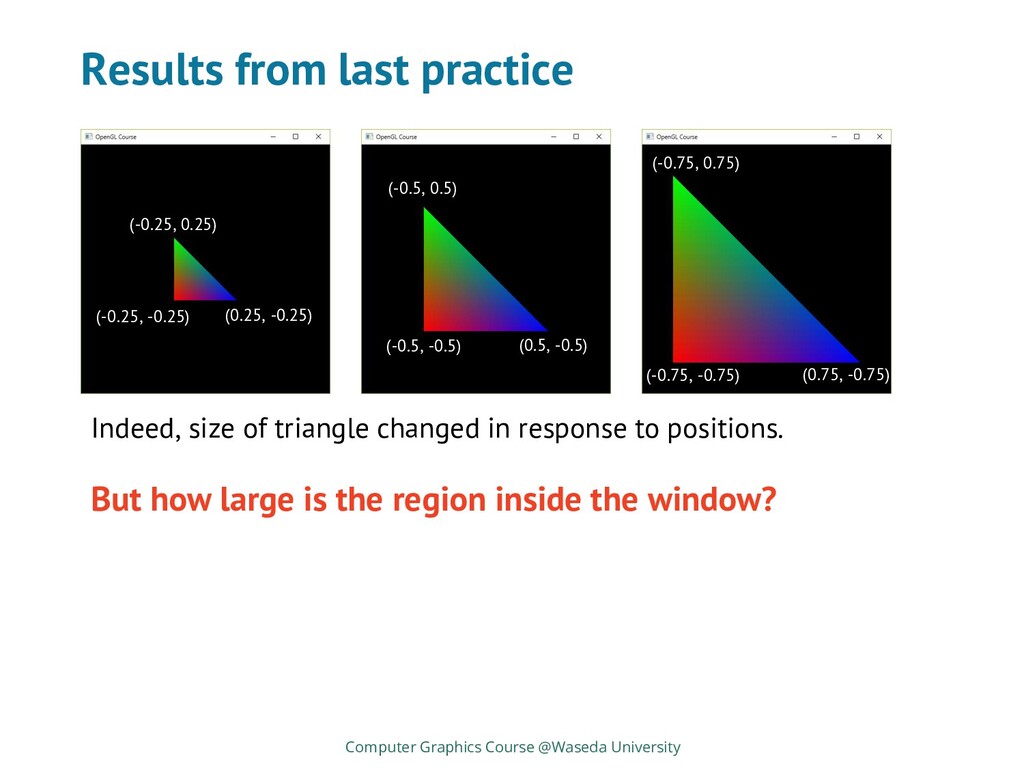
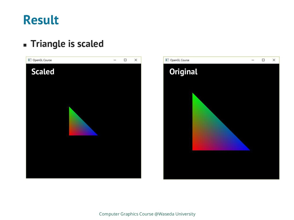
how large is the region inside the window? (-0.25, -0.25) (-0.25, 0.25) (0.25, -0.25) (-0.5, 0.5) (-0.5, -0.5) (0.5, -0.5) (-0.75, 0.75) (-0.75, -0.75) (0.75, -0.75) Indeed, size of triangle changed in response to positions.
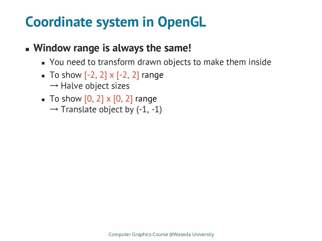
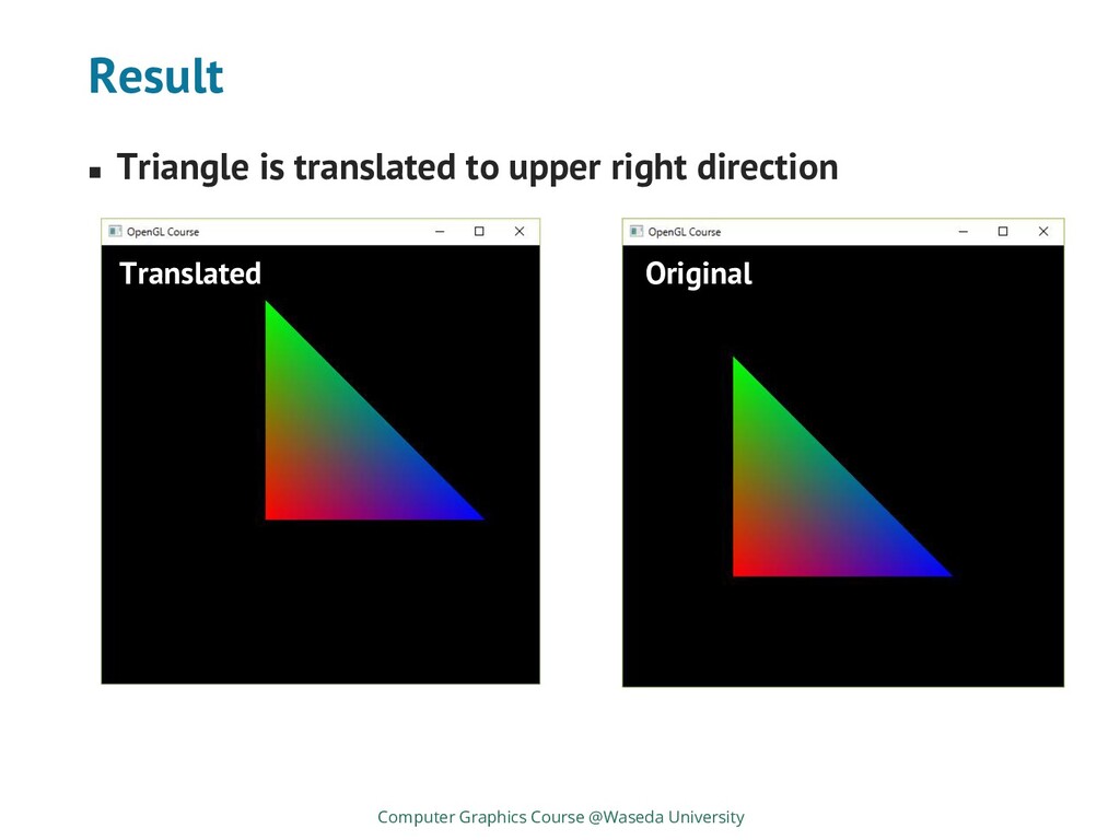
same! ◼ You need to transform drawn objects to make them inside ◼ To show [-2, 2] x [-2, 2] range → Halve object sizes ◼ To show [0, 2] x [0, 2] range → Translate object by (-1, -1) Computer Graphics Course @Waseda University
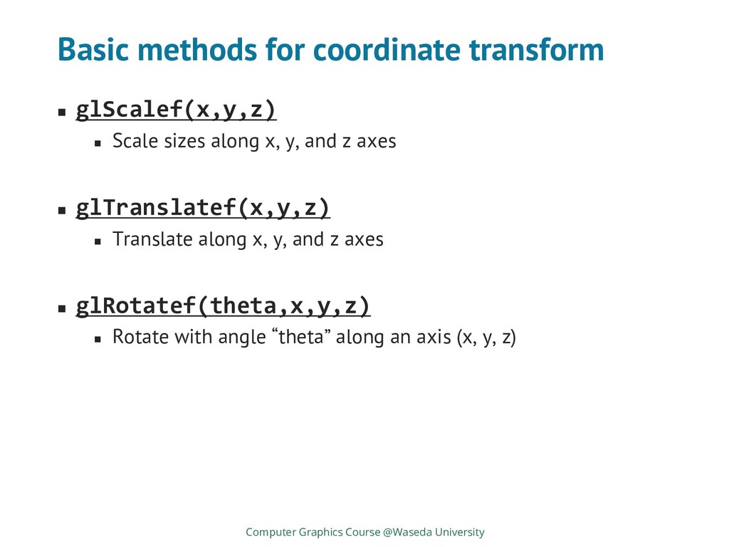
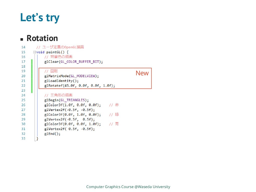
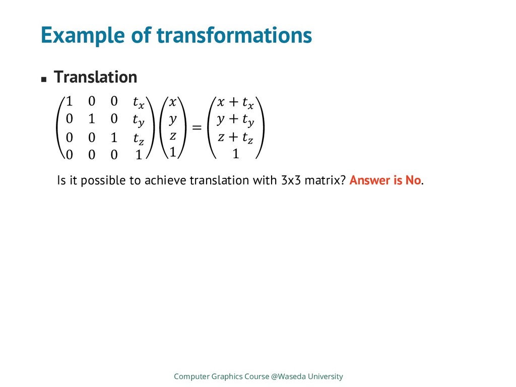
along x, y, and z axes ◼ glTranslatef(x,y,z) ◼ Translate along x, y, and z axes ◼ glRotatef(theta,x,y,z) ◼ Rotate with angle “theta” along an axis (x, y, z) Computer Graphics Course @Waseda University
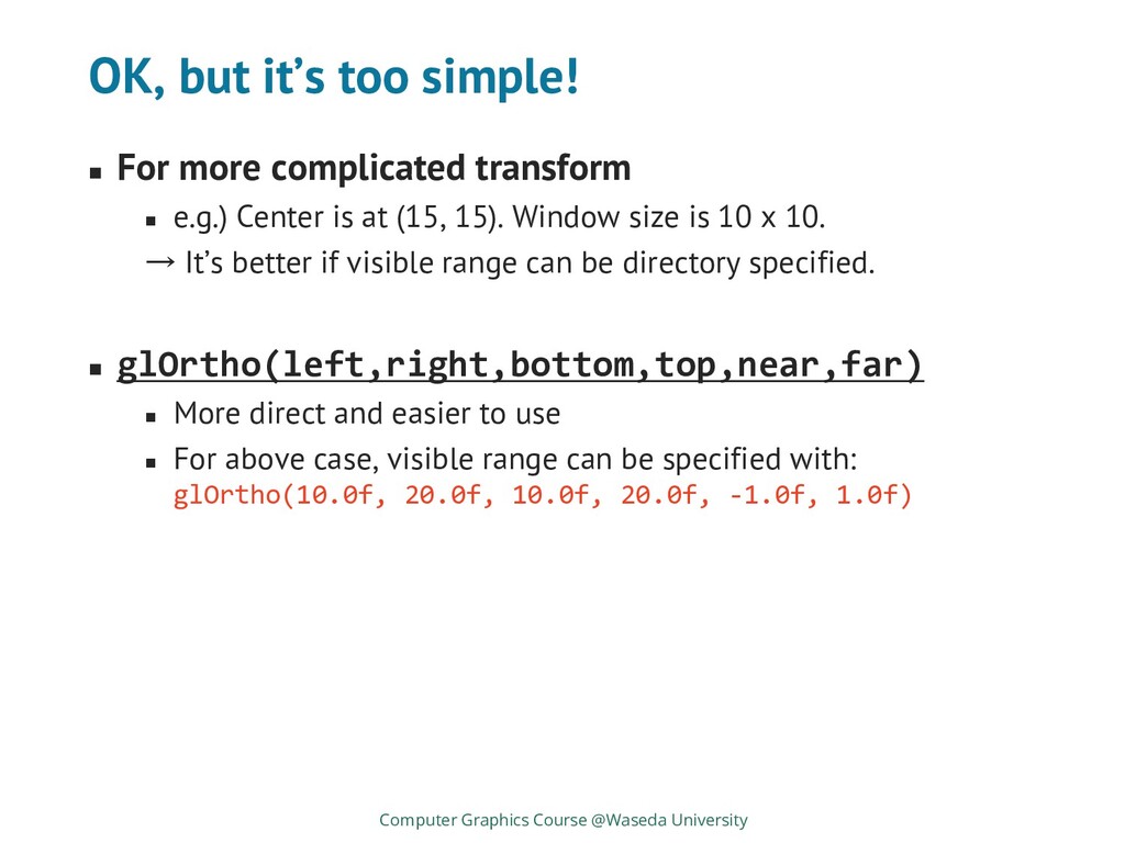
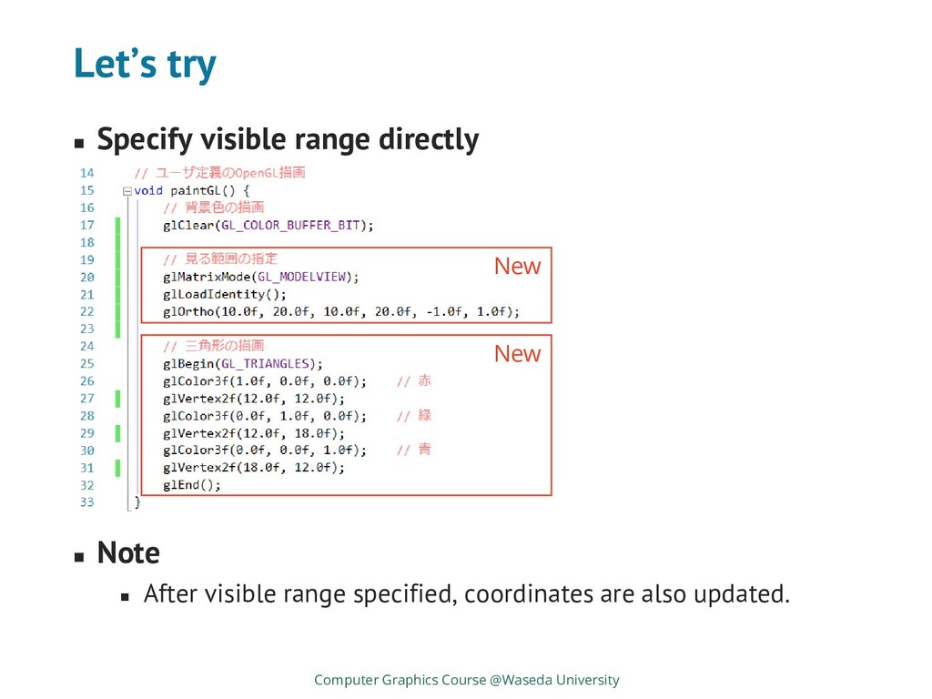
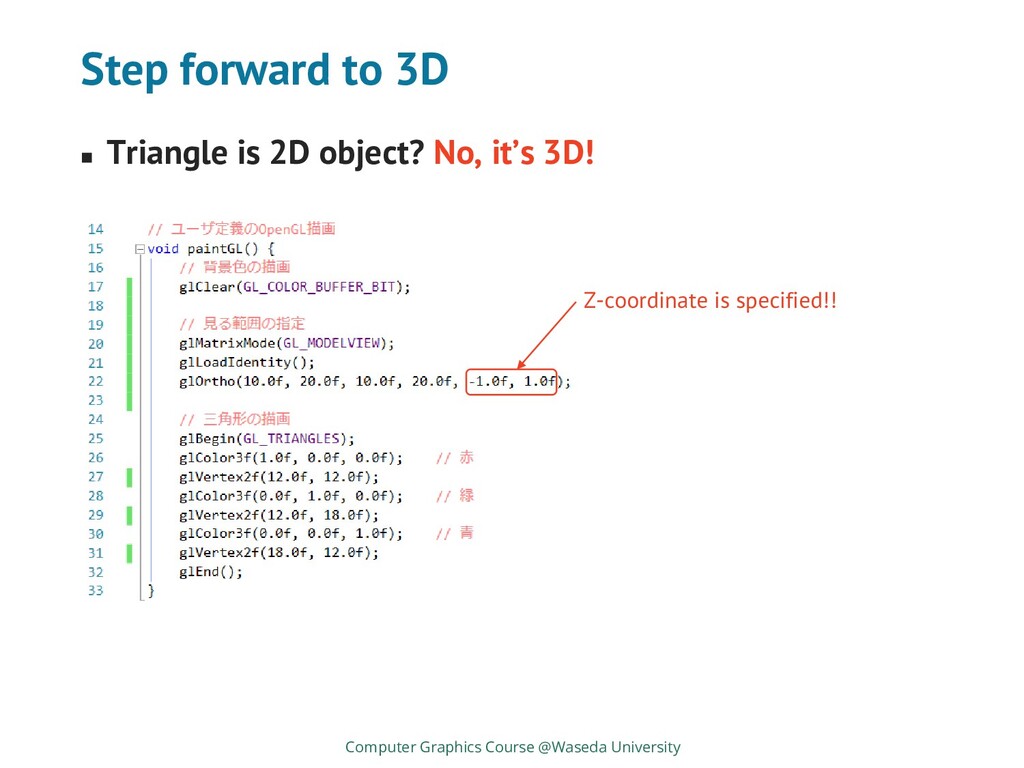
◼ e.g.) Center is at (15, 15). Window size is 10 x 10. → It’s better if visible range can be directory specified. ◼ glOrtho(left,right,bottom,top,near,far) ◼ More direct and easier to use ◼ For above case, visible range can be specified with: glOrtho(10.0f, 20.0f, 10.0f, 20.0f, -1.0f, 1.0f) Computer Graphics Course @Waseda University
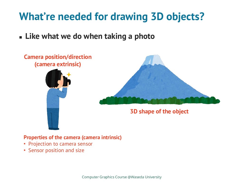
do when taking a photo Computer Graphics Course @Waseda University 3D shape of the object Camera position/direction (camera extrinsic) Properties of the camera (camera intrinsic) • Projection to camera sensor • Sensor position and size
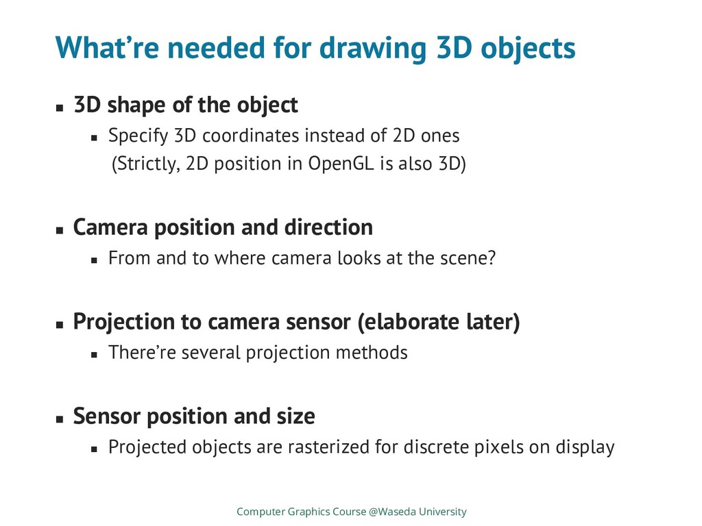
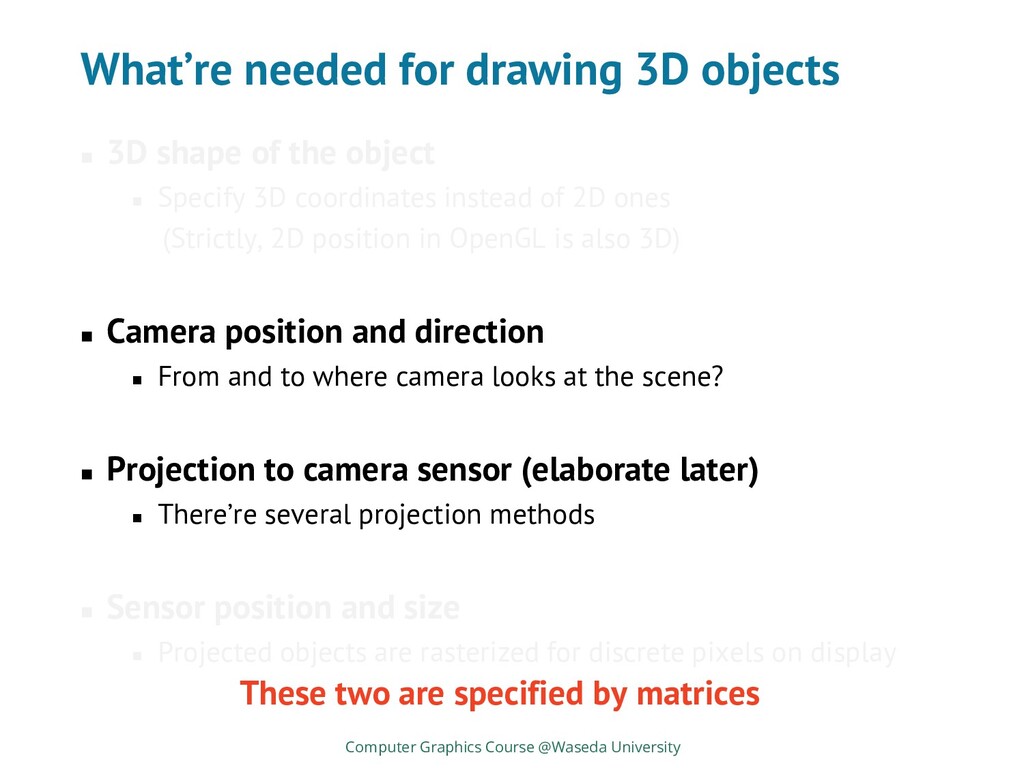
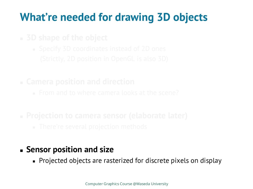
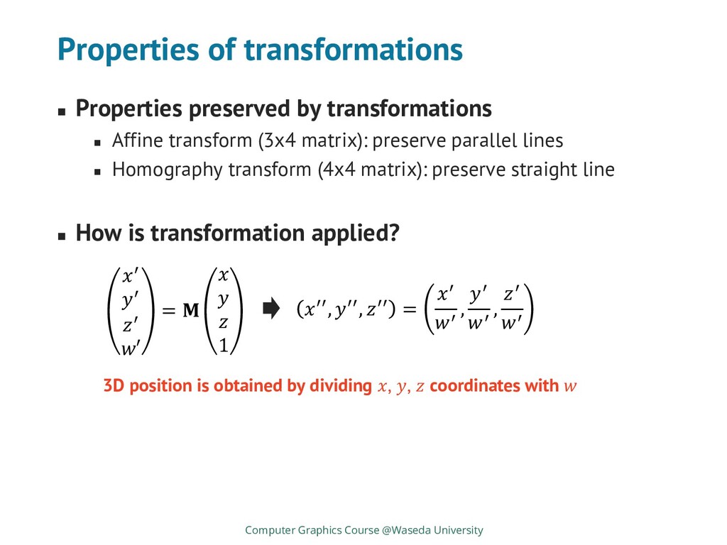
the object ◼ Specify 3D coordinates instead of 2D ones (Strictly, 2D position in OpenGL is also 3D) ◼ Camera position and direction ◼ From and to where camera looks at the scene? ◼ Projection to camera sensor (elaborate later) ◼ There’re several projection methods ◼ Sensor position and size ◼ Projected objects are rasterized for discrete pixels on display Computer Graphics Course @Waseda University
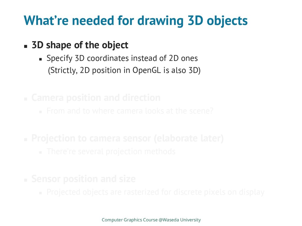
the object ◼ Specify 3D coordinates instead of 2D ones (Strictly, 2D position in OpenGL is also 3D) ◼ Camera position and direction ◼ From and to where camera looks at the scene? ◼ Projection to camera sensor (elaborate later) ◼ There’re several projection methods ◼ Sensor position and size ◼ Projected objects are rasterized for discrete pixels on display Computer Graphics Course @Waseda University
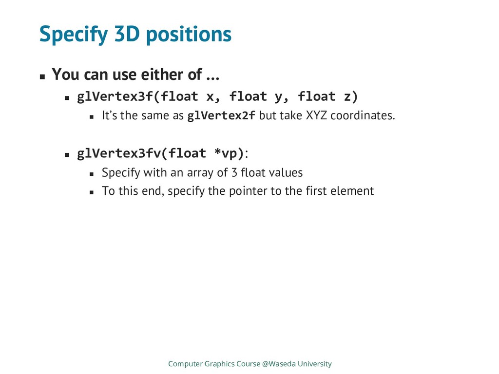
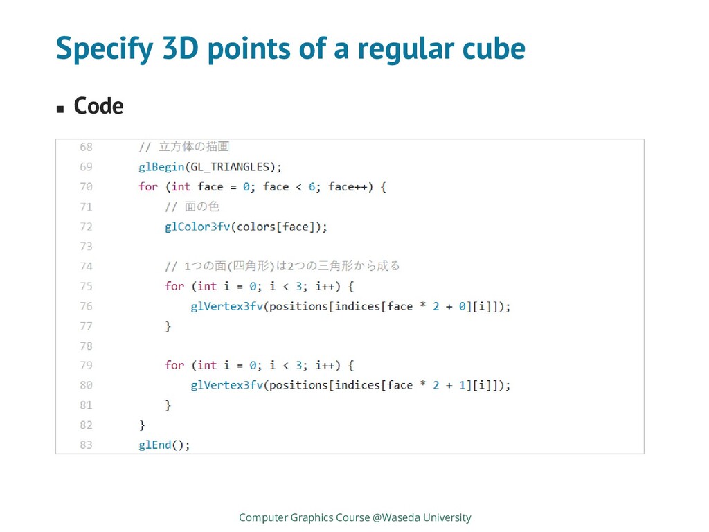
◼ glVertex3f(float x, float y, float z) ◼ It’s the same as glVertex2f but take XYZ coordinates. ◼ glVertex3fv(float *vp): ◼ Specify with an array of 3 float values ◼ To this end, specify the pointer to the first element Computer Graphics Course @Waseda University
the object ◼ Specify 3D coordinates instead of 2D ones (Strictly, 2D position in OpenGL is also 3D) ◼ Camera position and direction ◼ From and to where camera looks at the scene? ◼ Projection to camera sensor (elaborate later) ◼ There’re several projection methods ◼ Sensor position and size ◼ Projected objects are rasterized for discrete pixels on display Computer Graphics Course @Waseda University These two are specified by matrices
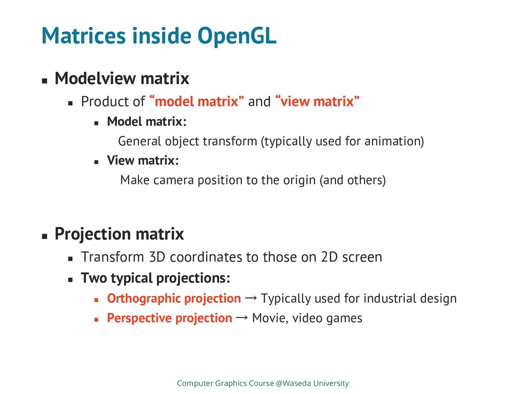
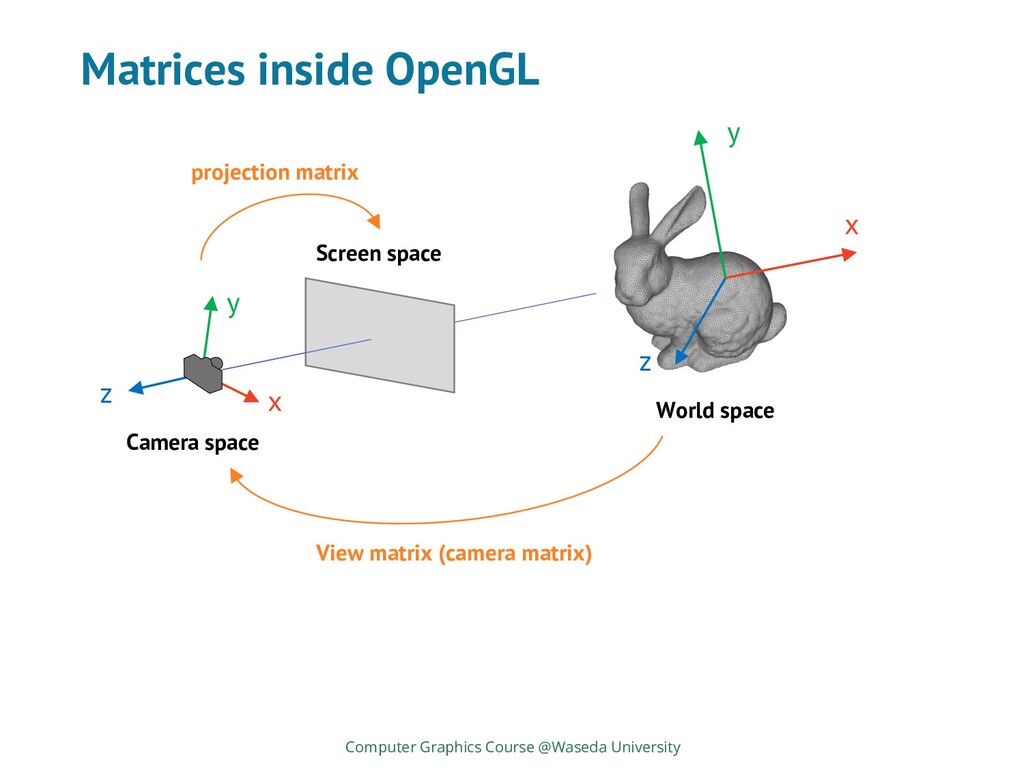
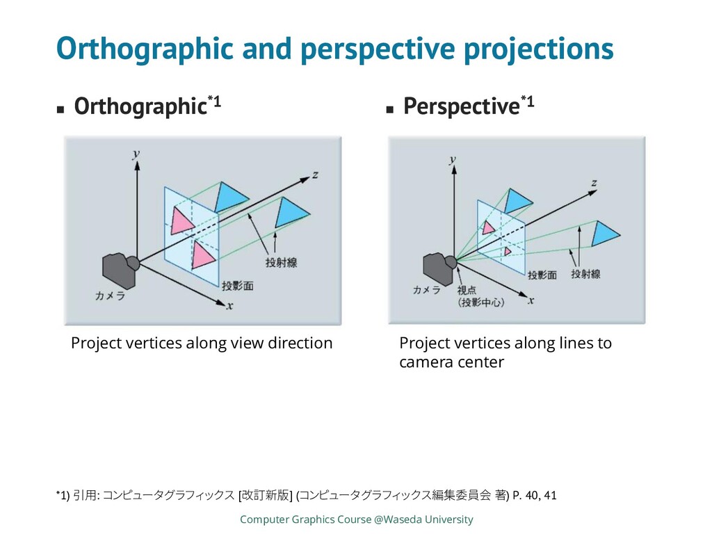
matrix” and “view matrix” ◼ Model matrix: General object transform (typically used for animation) ◼ View matrix: Make camera position to the origin (and others) ◼ Projection matrix ◼ Transform 3D coordinates to those on 2D screen ◼ Two typical projections: ◼ Orthographic projection → Typically used for industrial design ◼ Perspective projection → Movie, video games Computer Graphics Course @Waseda University
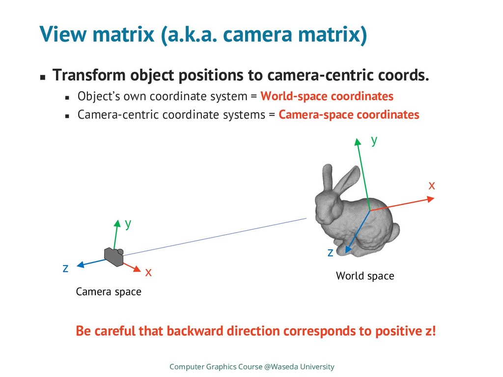
camera-centric coords. ◼ Object’s own coordinate system = World-space coordinates ◼ Camera-centric coordinate systems = Camera-space coordinates Computer Graphics Course @Waseda University x y z x y z Camera space World space Be careful that backward direction corresponds to positive z!
University ◼ Perspective*1 Project vertices along view direction Project vertices along lines to camera center *1) 引用: コンピュータグラフィックス [改訂新版] (コンピュータグラフィックス編集委員会 著) P. 40, 41
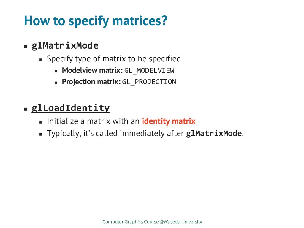
matrix to be specified ◼ Modelview matrix: GL_MODELVIEW ◼ Projection matrix: GL_PROJECTION ◼ glLoadIdentity ◼ Initialize a matrix with an identity matrix ◼ Typically, it’s called immediately after glMatrixMode. Computer Graphics Course @Waseda University
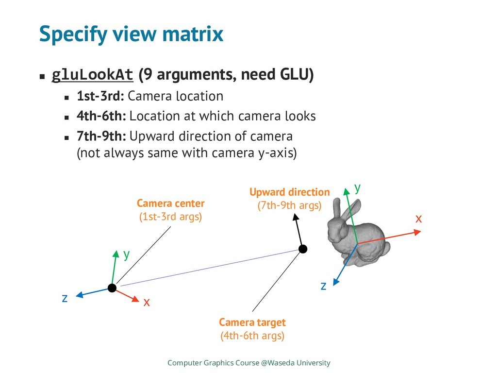
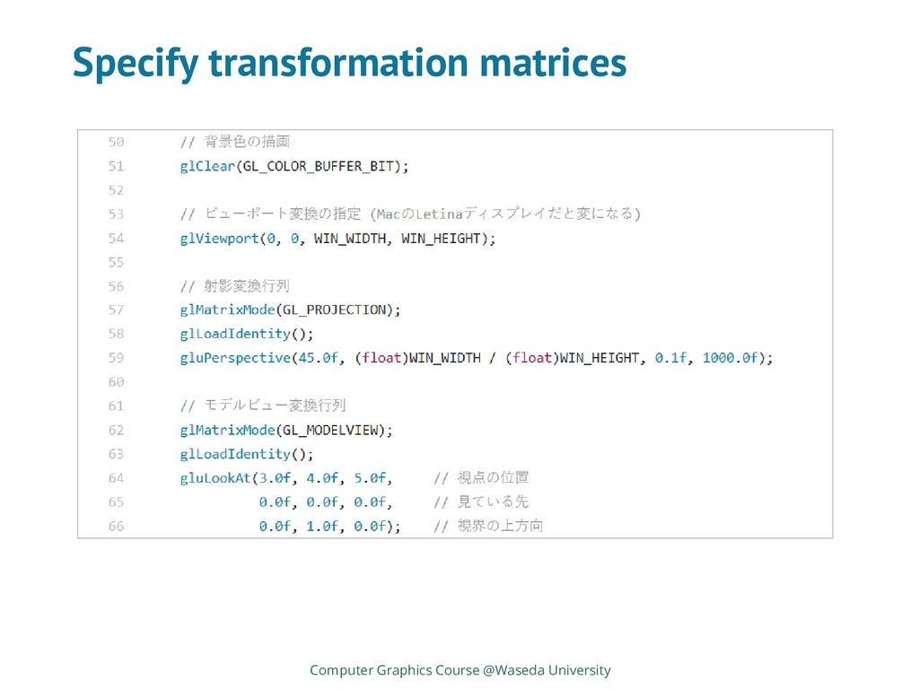
1st-3rd: Camera location ◼ 4th-6th: Location at which camera looks ◼ 7th-9th: Upward direction of camera (not always same with camera y-axis) Computer Graphics Course @Waseda University x y z x y z Camera center (1st-3rd args) Camera target (4th-6th args) Upward direction (7th-9th args)
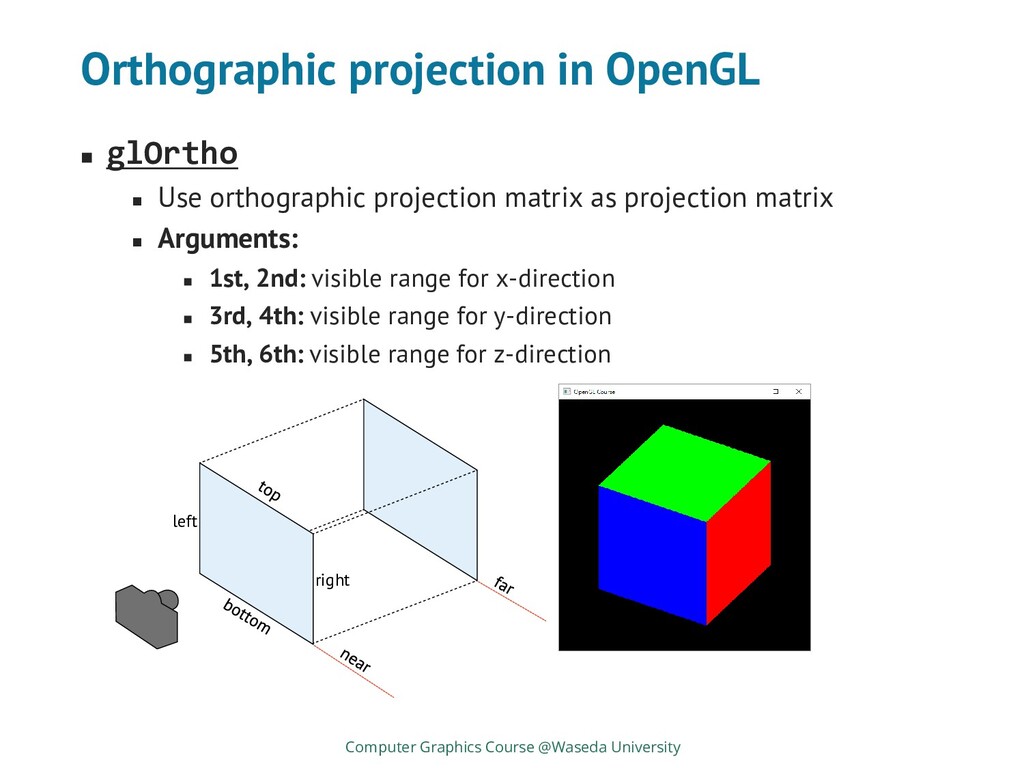
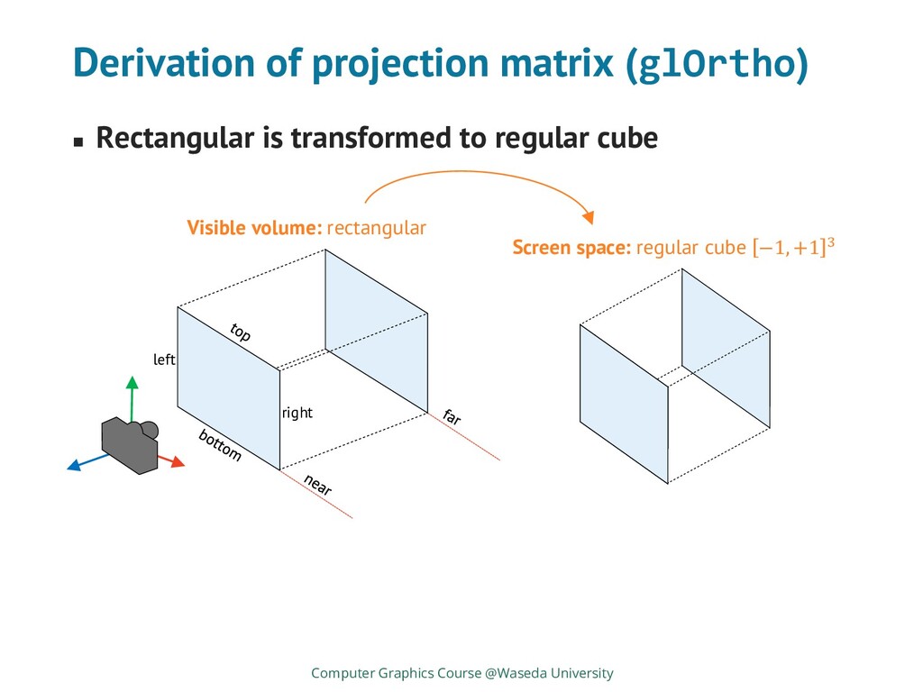
matrix as projection matrix ◼ Arguments: ◼ 1st, 2nd: visible range for x-direction ◼ 3rd, 4th: visible range for y-direction ◼ 5th, 6th: visible range for z-direction Computer Graphics Course @Waseda University left right
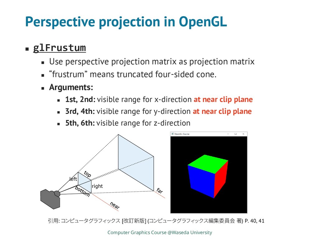
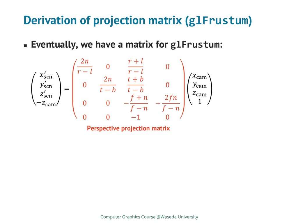
matrix as projection matrix ◼ “frustrum” means truncated four-sided cone. ◼ Arguments: ◼ 1st, 2nd: visible range for x-direction at near clip plane ◼ 3rd, 4th: visible range for y-direction at near clip plane ◼ 5th, 6th: visible range for z-direction Computer Graphics Course @Waseda University 引用: コンピュータグラフィックス [改訂新版] (コンピュータグラフィックス編集委員会 著) P. 40, 41 left right
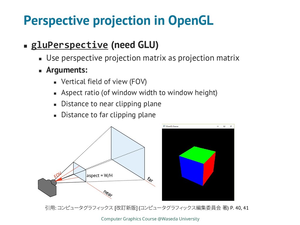
perspective projection matrix as projection matrix ◼ Arguments: ◼ Vertical field of view (FOV) ◼ Aspect ratio (of window width to window height) ◼ Distance to near clipping plane ◼ Distance to far clipping plane Computer Graphics Course @Waseda University 引用: コンピュータグラフィックス [改訂新版] (コンピュータグラフィックス編集委員会 著) P. 40, 41 aspect = W/H
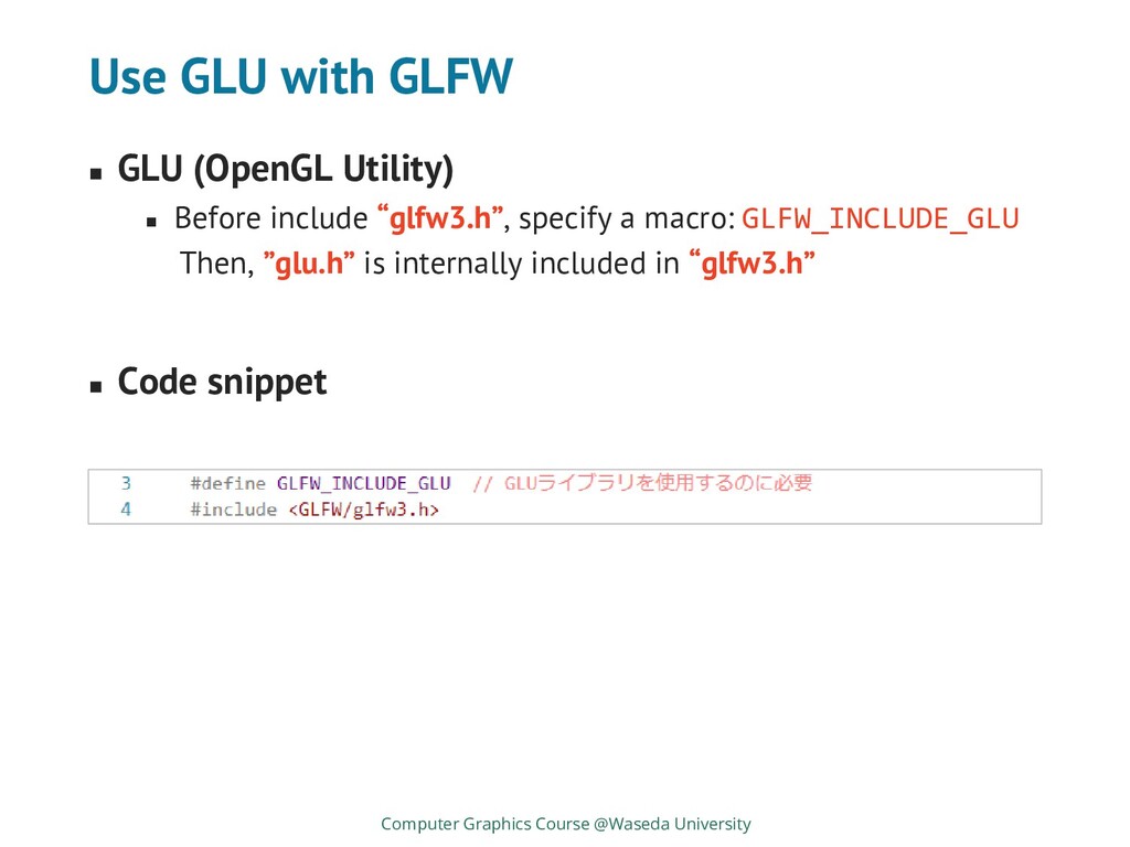
include “glfw3.h”, specify a macro: GLFW_INCLUDE_GLU Then, ”glu.h” is internally included in “glfw3.h” ◼ Code snippet Computer Graphics Course @Waseda University
the object ◼ Specify 3D coordinates instead of 2D ones (Strictly, 2D position in OpenGL is also 3D) ◼ Camera position and direction ◼ From and to where camera looks at the scene? ◼ Projection to camera sensor (elaborate later) ◼ There’re several projection methods ◼ Sensor position and size ◼ Projected objects are rasterized for discrete pixels on display Computer Graphics Course @Waseda University
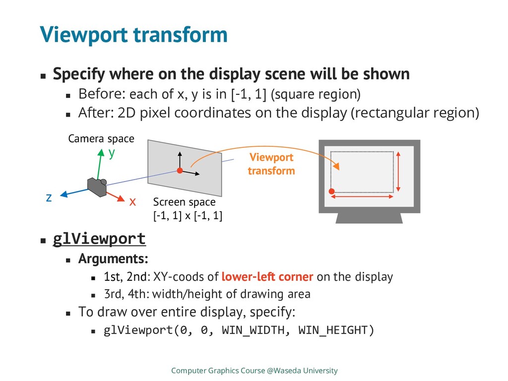
be shown ◼ Before: each of x, y is in [-1, 1] (square region) ◼ After: 2D pixel coordinates on the display (rectangular region) ◼ glViewport ◼ Arguments: ◼ 1st, 2nd: XY-coods of lower-left corner on the display ◼ 3rd, 4th: width/height of drawing area ◼ To draw over entire display, specify: ◼ glViewport(0, 0, WIN_WIDTH, WIN_HEIGHT) Computer Graphics Course @Waseda University x y z Camera space Screen space [-1, 1] x [-1, 1] Viewport transform
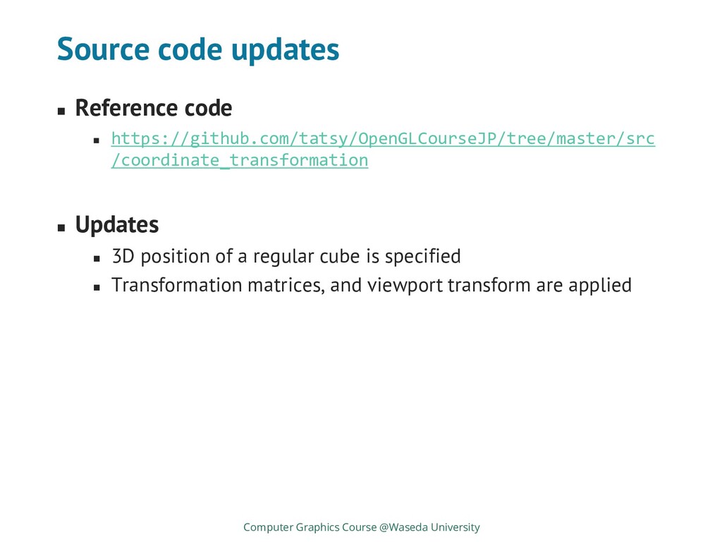
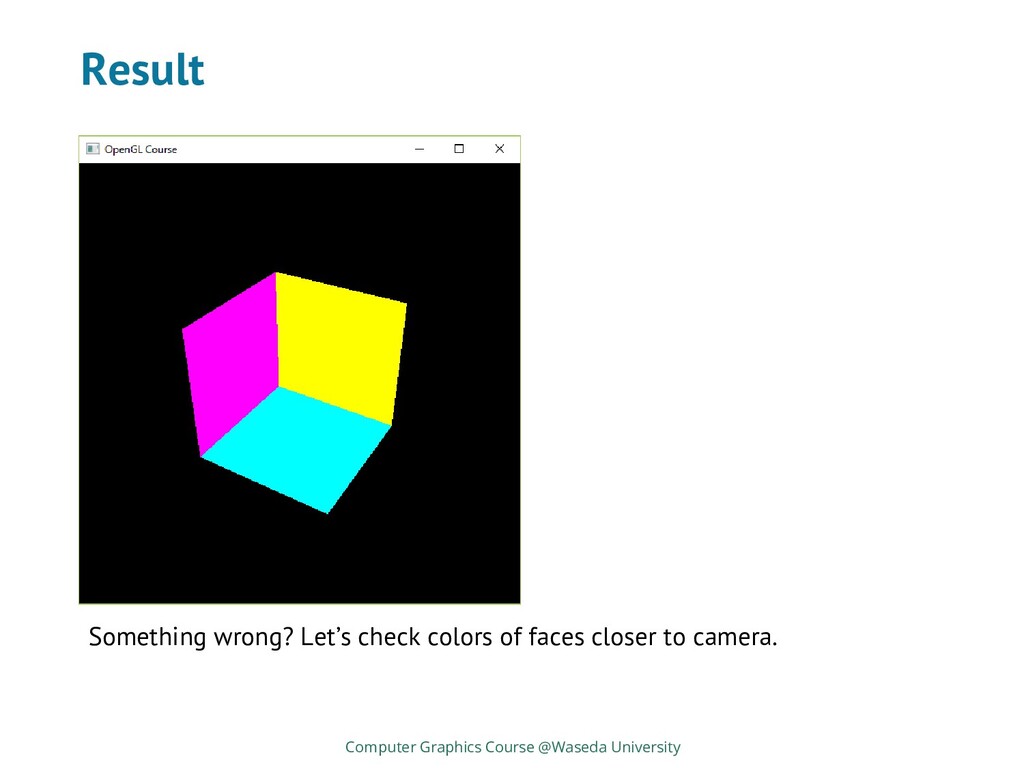
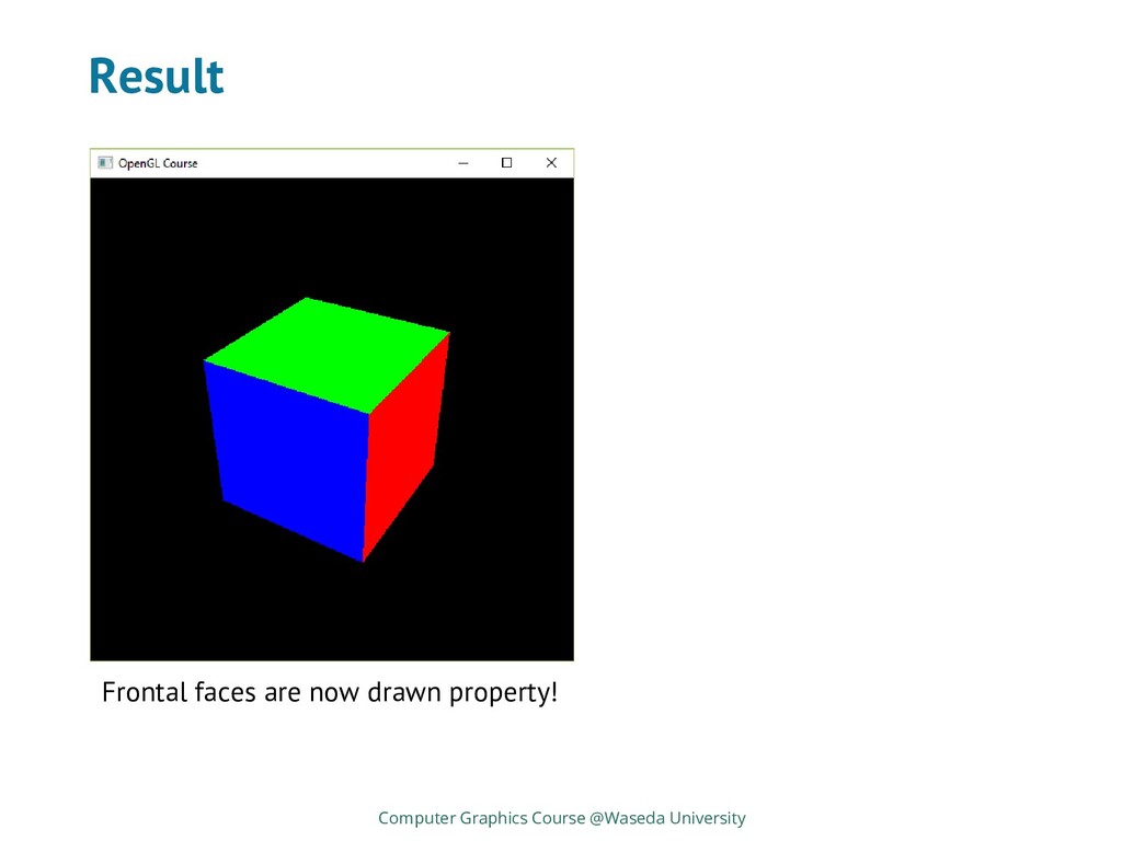
Updates ◼ 3D position of a regular cube is specified ◼ Transformation matrices, and viewport transform are applied Computer Graphics Course @Waseda University
from camera ◼ Algorithms for hidden face removal: ◼ Ray casting ◼ Depth sort method ◼ Scanline method ◼ Z-buffer method ◼ In OpenGL, Z-buffer method is used because: ◼ Its implementation is quite simplicity ◼ It’s easy to be parallelized using GPU Computer Graphics Course @Waseda University
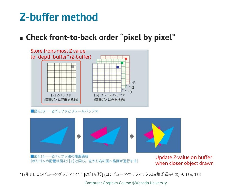
Graphics Course @Waseda University *1) 引用: コンピュータグラフィックス [改訂新版] (コンピュータグラフィックス編集委員会 著) P. 133, 134 Store front-most Z value to “depth buffer” (Z-buffer) Update Z-value on buffer when closer object drawn
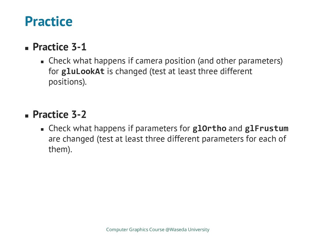
position (and other parameters) for gluLookAt is changed (test at least three different positions). ◼ Practice 3-2 ◼ Check what happens if parameters for glOrtho and glFrustum are changed (test at least three different parameters for each of them). Computer Graphics Course @Waseda University
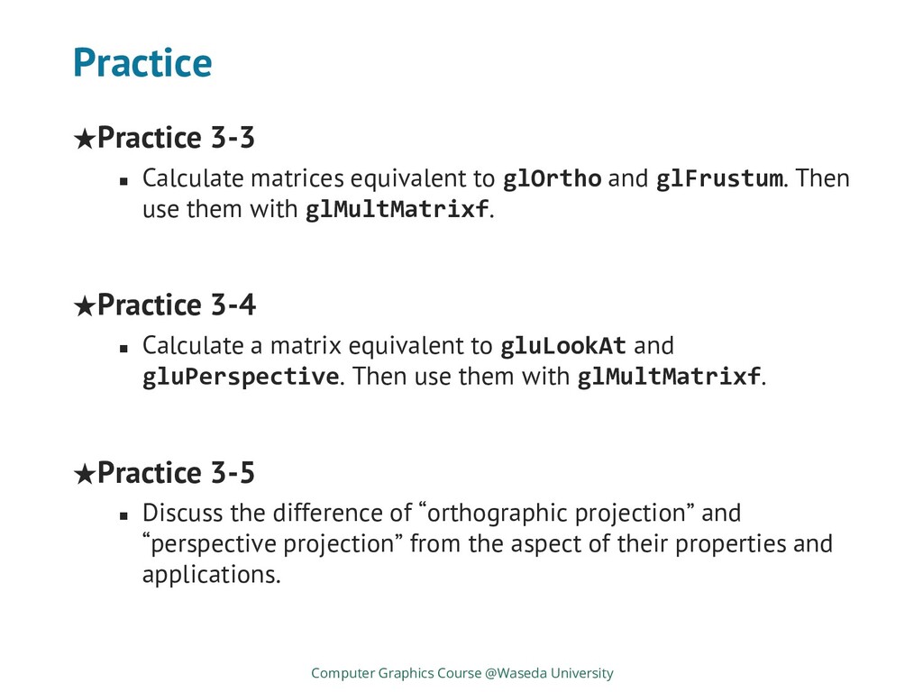
glFrustum. Then use them with glMultMatrixf. ★Practice 3-4 ◼ Calculate a matrix equivalent to gluLookAt and gluPerspective. Then use them with glMultMatrixf. ★Practice 3-5 ◼ Discuss the difference of “orthographic projection” and “perspective projection” from the aspect of their properties and applications. Computer Graphics Course @Waseda University
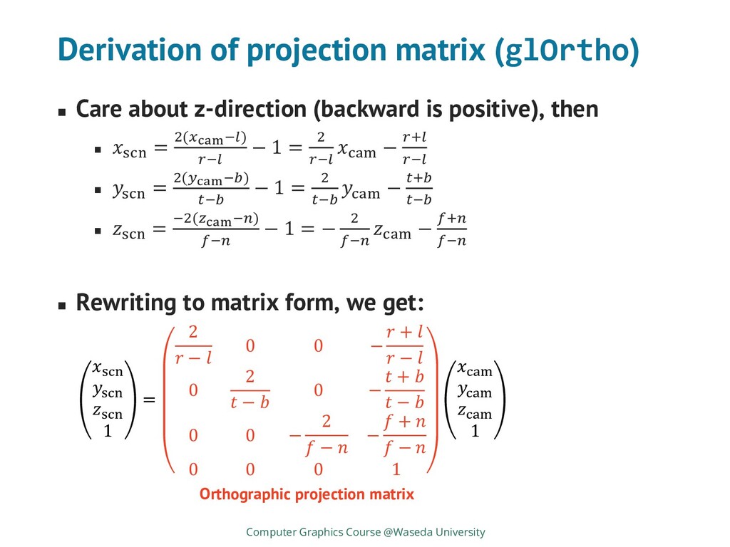
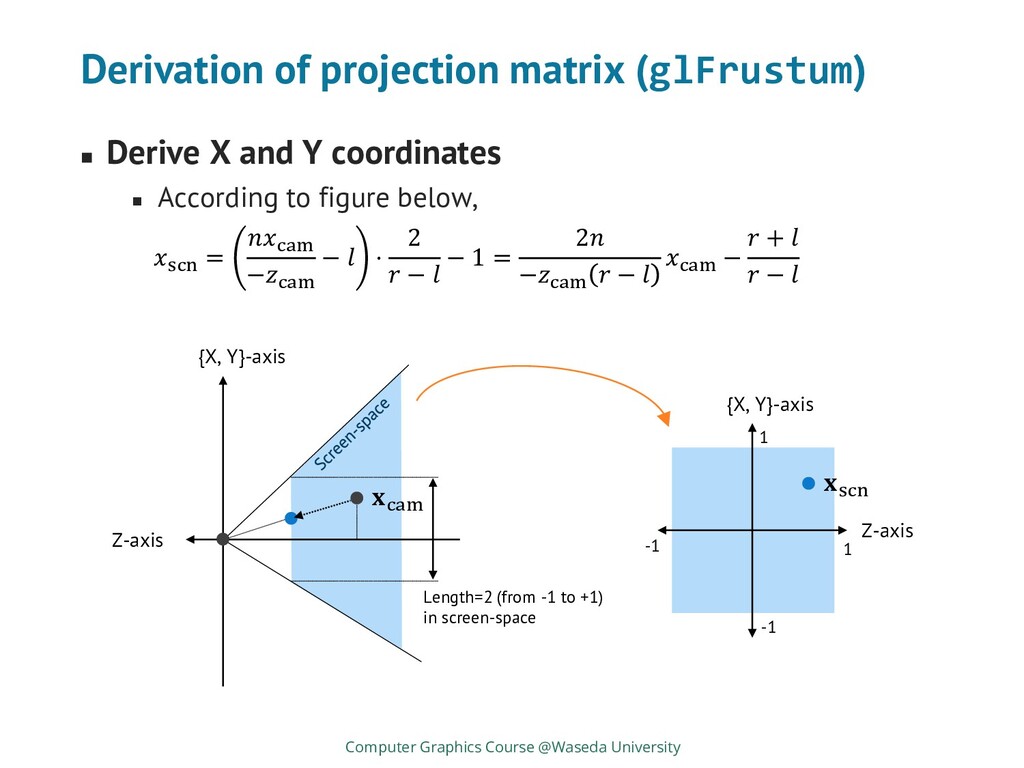
is converted to regular cube ◼ Frustrum in camera-space is converted to regular box Computer Graphics Course @Waseda University Y-axis Z-axis 𝐱cam 𝐱scn 1 1 -1 -1 Camera space: frustum Screen space: regular cube Y-axis Z-axis near far
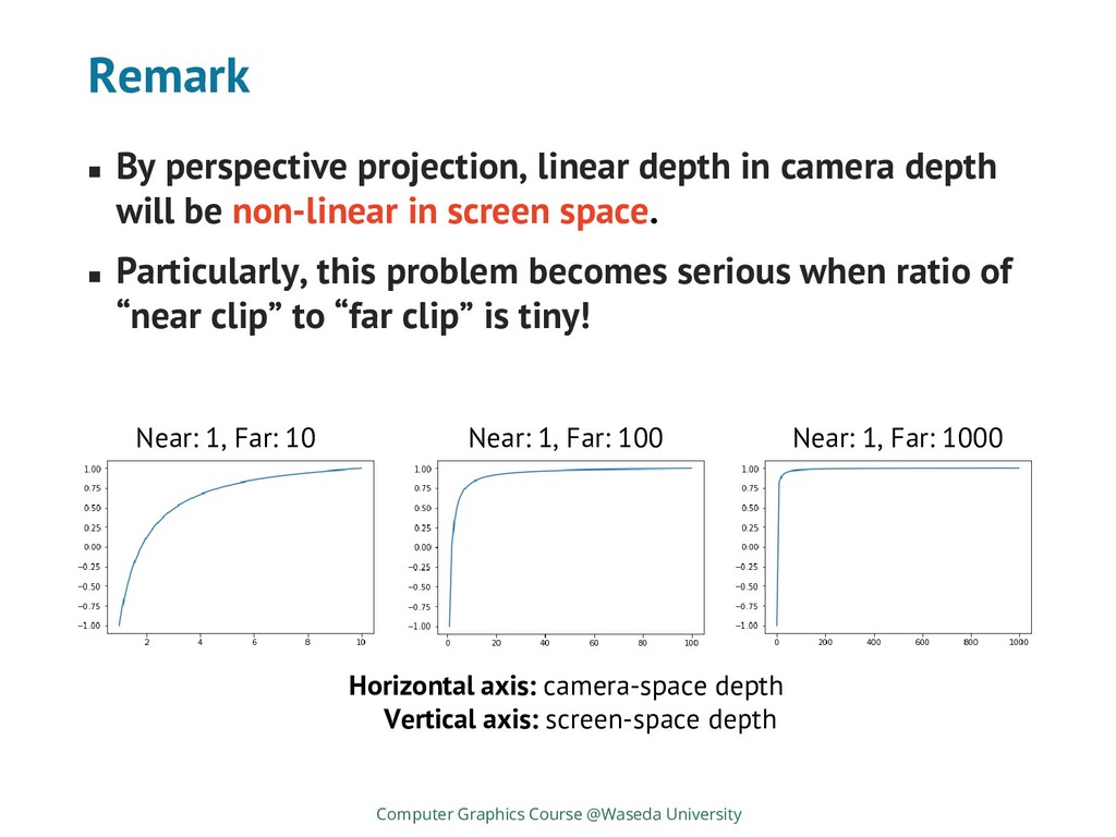
will be non-linear in screen space. ◼ Particularly, this problem becomes serious when ratio of “near clip” to “far clip” is tiny! Computer Graphics Course @Waseda University Horizontal axis: camera-space depth Vertical axis: screen-space depth Near: 1, Far: 10 Near: 1, Far: 100 Near: 1, Far: 1000