Upgrade to Pro — share decks privately, control downloads, hide ads and more …

E716_lec02

 E716_lec02

7th Year, Integrated Technical Education Cluster AlAmeeria‎
lec#2, Mobile Communication Systems

Ahmad El-Banna

October 21, 2014
Tweet

More Decks by Ahmad El-Banna

Other Decks in Education

Transcript

  1. Lecture #2 Basic Concepts of Wireless Transmission (p1) Instructor: Dr.

    Ahmad El-Banna October 2014 E-716-A Mobile Communications Systems Integrated Technical Education Cluster At AlAmeeria‎ © Ahmad El-Banna
  2. Agenda Frequencies for Radio Transmission Signals for conveying Information Analog

    and Digital Data Transmission Signal Propagation 2 E-716-A, Lec#2 , Oct 2014 © Ahmad El-Banna
  3. Frequencies for communication 4 E-716-A, Lec#2 , Oct 2014 ©

    Ahmad El-Banna • VLF = Very Low Frequency UHF = Ultra High Frequency • LF = Low Frequency SHF = Super High Frequency • MF = Medium Frequency EHF = Extra High Frequency • HF = High Frequency UV = Ultraviolet Light • VHF = Very High Frequency • Frequency and wave length •  = c/f • wave length , speed of light c  3x10⁸m/s, frequency f 1 Mm 300 Hz 10 km 30 kHz 100 m 3 MHz 1 m 300 MHz 10 mm 30 GHz 100 m 3 THz 1 m 300 THz visible light VLF LF MF HF VHF UHF SHF EHF infrared UV optical transmission coax cable twisted pair
  4. Example frequencies for mobile communication • VHF-/UHF-ranges for mobile radio

    • simple, small antenna for cars • deterministic propagation characteristics, reliable connections • SHF and higher for directed radio links, satellite communication • small antenna, beam forming • large bandwidth available • Wireless LANs use frequencies in UHF to SHF range • some systems planned up to EHF • limitations due to absorption by water and oxygen molecules • weather dependent fading, signal loss caused by heavy rainfall etc. 5 E-716-A, Lec#2 , Oct 2014 © Ahmad El-Banna
  5. Frequencies and regulations • In general: ITU-R holds auctions for

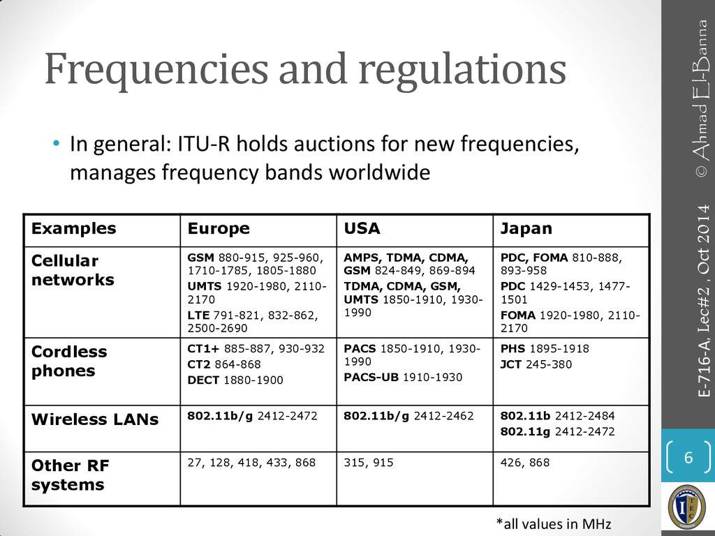
    new frequencies, manages frequency bands worldwide 6 E-716-A, Lec#2 , Oct 2014 © Ahmad El-Banna Examples Europe USA Japan Cellular networks GSM 880-915, 925-960, 1710-1785, 1805-1880 UMTS 1920-1980, 2110- 2170 LTE 791-821, 832-862, 2500-2690 AMPS, TDMA, CDMA, GSM 824-849, 869-894 TDMA, CDMA, GSM, UMTS 1850-1910, 1930- 1990 PDC, FOMA 810-888, 893-958 PDC 1429-1453, 1477- 1501 FOMA 1920-1980, 2110- 2170 Cordless phones CT1+ 885-887, 930-932 CT2 864-868 DECT 1880-1900 PACS 1850-1910, 1930- 1990 PACS-UB 1910-1930 PHS 1895-1918 JCT 245-380 Wireless LANs 802.11b/g 2412-2472 802.11b/g 2412-2462 802.11b 2412-2484 802.11g 2412-2472 Other RF systems 27, 128, 418, 433, 868 315, 915 426, 868 *all values in MHz
  6. Signals • physical representation of data • function of time

    • signal parameters: parameters representing the value of data • Classification: • continuous time/discrete time • continuous values/discrete values • analog signal = continuous time and continuous values • digital signal = discrete time and discrete values 8 E-716-A, Lec#2 , Oct 2014 © Ahmad El-Banna
  7. Time Domain Concepts • Analog signal - signal intensity varies

    in a smooth fashion over time • No breaks or discontinuities in the signal • Digital signal - signal intensity maintains a constant level for some period of time and then changes to another constant level • Periodic signal - analog or digital signal pattern that repeats over time • s(t +T ) = s(t ) -∞< t < +∞ • where T is the period of the signal • Aperiodic signal - analog or digital signal pattern that doesn't repeat over time • Peak amplitude (A) - maximum value or strength of the signal over time; typically measured in volts 9 E-716-A, Lec#2 , Oct 2014 © Ahmad El-Banna
  8. Time Domain Concepts.. • Frequency (f ) • Rate, in

    cycles per second, or Hertz (Hz) at which the signal repeats • Period (T ) - amount of time it takes for one repetition of the signal • T = 1/f • Phase () - measure of the relative position in time within a single period of a signal • Wavelength () - distance occupied by a single cycle of the signal • Or, the distance between two points of corresponding phase of two consecutive cycles 10 E-716-A, Lec#2 , Oct 2014 © Ahmad El-Banna
  9. Fourier representation of periodic signals • Signals can also be

    expressed as a function of frequency • Signal consists of components of different frequencies 11 E-716-A, Lec#2 , Oct 2014 © Ahmad El-Banna ) 2 cos( ) 2 sin( 2 1 ) ( 1 1 nft b nft a c t g n n n n            1 0 1 0 t t ideal periodic signal real composition (based on harmonics)
  10. Frequency Domain Concepts • Fundamental frequency - when all frequency

    components of a signal are integer multiples of one frequency, it’s referred to as the fundamental frequency. • Spectrum - range of frequencies that a signal contains. • Absolute bandwidth - width of the spectrum of a signal. • Effective bandwidth (or just bandwidth) - narrow band of frequencies that most of the signal’s energy is contained in. • Any electromagnetic signal can be shown to consist of a collection of periodic analog signals (sine waves) at different amplitudes, frequencies, and phases. • The period of the total signal is equal to the period of the fundamental frequency. 12 E-716-A, Lec#2 , Oct 2014 © Ahmad El-Banna
  11. Signals representations • Different representations of signals • amplitude (amplitude

    domain) • frequency spectrum (frequency domain) • phase state diagram (amplitude M and phase  in polar coordinates) 13 E-716-A, Lec#2 , Oct 2014 © Ahmad El-Banna f [Hz] A [V]  I= M cos  Q = M sin   A [V] t[s]
  12. Data Communication Terms • Data - entities that convey meaning,

    or information • Signals - electric or electromagnetic representations of data • Transmission - communication of data by the propagation and processing of signals • Examples of Analog/Digital Data: • Analog • Video • Audio • Digital • Text • Integers 15 E-716-A, Lec#2 , Oct 2014 © Ahmad El-Banna
  13. Analog and Digital Signals • A continuously varying electromagnetic wave

    that may be propagated over a variety of media, depending on frequency • Examples of media: • Copper wire media (twisted pair and coaxial cable) • Fiber optic cable • Atmosphere or space propagation • Analog signals can propagate analog and digital data • A sequence of voltage pulses that may be transmitted over a copper wire medium • Generally cheaper than analog signaling • Less susceptible to noise interference • Suffer more from attenuation • Digital signals can propagate analog and digital data 16 E-716-A, Lec#2 , Oct 2014 © Ahmad El-Banna Analog Digital again 
  14. Analog and Digital Signaling of Analog and Digital Data 17

    E-716-A, Lec#2 , Oct 2014 © Ahmad El-Banna
  15. Reasons for Choosing Data and Signal Combinations • Digital data,

    digital signal • Equipment for encoding is less expensive than digital-to-analog equipment • Analog data, digital signal • Conversion permits use of modern digital transmission and switching equipment • Digital data, analog signal • Some transmission media will only propagate analog signals • Examples include optical fiber and satellite • Analog data, analog signal • Analog data easily converted to analog signal 18 E-716-A, Lec#2 , Oct 2014 © Ahmad El-Banna
  16. Analog and Digital Transmission • Transmitting analog signals without regard

    to their content. • will suffer attenuation that limits the length of the transmission link. • To achieve longer distances, include amplifiers that boost the energy in the signal. • But, the amplifier also boosts the noise components. • With amplifiers cascaded to achieve long distance, the signal becomes more and more distorted. • For analog data, small distortion can be tolerated and the data remain intelligible. • But, for digital data transmitted as analog signals, cascaded amplifiers will introduce errors. • is concerned with the content of the signal. • can be propagated only a limited distance before attenuation endangers the integrity of the data. Digital Signal • To achieve greater distances, repeaters are used. • A repeater receives the digital signal, recovers the pattern of ones and zeros, and retransmits a new signal. • Thus, the attenuation is overcome. 19 E-716-A, Lec#2 , Oct 2014 © Ahmad El-Banna Analog Digital
  17. Channel Capacity • Impairments, such as noise, limit data rate

    that can be achieved • For digital data, to what extent do impairments limit data rate? • Channel Capacity – the maximum rate at which data can be transmitted over a given communication path, or channel, under given conditions • Data rate - rate at which data can be communicated (bps) • Bandwidth - the bandwidth of the transmitted signal as constrained by the transmitter and the nature of the transmission medium (Hertz) • Noise - average level of noise over the communications path • Error rate - rate at which errors occur • Error = transmit 1 and receive 0; transmit 0 and receive 1 20 E-716-A, Lec#2 , Oct 2014 © Ahmad El-Banna
  18. Relationship between Data Rate and Bandwidth • There is a

    direct relationship between the information- carrying capacity of a signal and its bandwidth • The greater the bandwidth, the higher the information- carrying capacity • Conclusions • Any digital waveform will have infinite bandwidth • BUT the transmission system will limit the bandwidth that can be transmitted • AND, for any given medium, the greater the bandwidth transmitted, the greater the cost • HOWEVER, limiting the bandwidth creates distortions 21 E-716-A, Lec#2 , Oct 2014 © Ahmad El-Banna
  19. Signal-to-Noise Ratio 22 E-716-A, Lec#2 , Oct 2014 © Ahmad

    El-Banna • Ratio of the power in a signal to the power contained in the noise that’s present at a particular point in the transmission • Typically measured at a receiver • Signal-to-noise ratio (SNR, or S/N) • A high SNR means a high-quality signal, low number of required intermediate repeaters • SNR sets upper bound on achievable data rate power noise power signal log 10 ) ( 10 dB  SNR
  20. Nyquist Bandwidth • if the rate of signal transmission is

    2B, then a signal with frequencies no greater than B is sufficient to carry the signal rate. • Given a bandwidth of B, the highest signal rate that can be carried is 2B. • This limitation is due to the effect of intersymbol interference, such as is produced by delay distortion. • For binary signals (two voltage levels) • C = 2B • With multilevel signaling • C = 2B log2 M • M = number of discrete signal or voltage levels 24 E-716-A, Lec#2 , Oct 2014 © Ahmad El-Banna
  21. Shannon Capacity Formula • Nyquist's formula indicates that, all other

    things being equal, doubling the band- width doubles the data rate. • Now consider the relationship among data rate, noise, and error rate. • Shannon Equation: • Represents theoretical maximum that can be achieved • In practice, only much lower rates achieved • Formula assumes white noise (thermal noise) • Impulse noise is not accounted for • Attenuation distortion or delay distortion not accounted for 25 E-716-A, Lec#2 , Oct 2014 © Ahmad El-Banna   SNR 1 log 2   B C
  22. Signal Propagation Ranges • Transmission range • communication possible •

    low error rate • Detection range • detection of the signal possible • no communication possible • Interference range • signal may not be detected • signal adds to the background noise • Warning: figure misleading – bizarre shaped, time-varying ranges in reality! 27 E-716-A, Lec#2 , Oct 2014 © Ahmad El-Banna distance sender transmission detection interference
  23. Signal Propagation • Propagation in free space always like light

    (straight line) • Receiving power proportional to 1/d² in vacuum – much more in real environments, e.g., d3.5…d4 (d = distance between sender and receiver) • Receiving power additionally influenced by • fading (frequency dependent) • shadowing • reflection at large obstacles • refraction depending on the density of a medium • scattering at small obstacles • diffraction at edges 28 E-716-A, Lec#2 , Oct 2014 © Ahmad El-Banna reflection scattering diffraction shadowing refraction
  24. Real World Examples 29 E-716-A, Lec#2 , Oct 2014 ©

    Ahmad El-Banna www.ihe.kit.edu/index.php
  25. Multipath Propagation • Signal can take many different paths between

    sender and receiver due to reflection, scattering, diffraction • Time dispersion: signal is dispersed over time • interference with “neighbor” symbols, Inter Symbol Interference (ISI) • The signal reaches a receiver directly and phase shifted • distorted signal depending on the phases of the different parts 30 E-716-A, Lec#2 , Oct 2014 © Ahmad El-Banna signal at sender signal at receiver LOS pulses multipath pulses LOS (line-of-sight)
  26. Effects of Mobility • Channel characteristics change over time and

    location • signal paths change • different delay variations of different signal parts • different phases of signal parts •  quick changes in the power received (short term fading) • Additional changes in • distance to sender • obstacles further away •  slow changes in the average power received (long term fading) 31 E-716-A, Lec#2 , Oct 2014 © Ahmad El-Banna short term fading long term fading power t
  27. • For more details, refer to: • Chapter 2, J.

    Chiller, Mobile Communications, 2003. • Chapter 2, W. Stallings, Wireless Communications and Networks, 2005. • The lecture is available onlin e at: • https://speakerdeck.com/ahmad_elbanna • For inquires, send to: • [email protected][email protected] 32 E-716-A, Lec#2 , Oct 2014 © Ahmad El-Banna