Upgrade to Pro
— share decks privately, control downloads, hide ads and more …
Speaker Deck
Features
Speaker Deck
PRO
Sign in
Sign up for free
Search
Search
ECE312_lec03
Search
Ahmad El-Banna
October 22, 2014
Education
1k
1
Share
Embed
Copy iframe code
Copy JS code
Copy link
Start on current slide
ECE312_lec03
3rd Year, Faculty of Eng. at Shoubra
lec#3, Electronic Circuits (A)
Ahmad El-Banna
October 22, 2014
More Decks by Ahmad El-Banna
See All by Ahmad El-Banna
E716_lec12
ahmad_elbanna
0
1.7k
J601_lec12
ahmad_elbanna
1
1k
E716_lec11
ahmad_elbanna
1
650
E716_lec10
ahmad_elbanna
0
600
J601_lec11
ahmad_elbanna
1
1k
J601_lec10
ahmad_elbanna
1
1k
E716_lec09
ahmad_elbanna
0
740
J601_lec09
ahmad_elbanna
0
600
J601_lec08.pdf
ahmad_elbanna
1
1.3k
Other Decks in Education
See All in Education
0526
cbtlibrary
0
190
アラムコSTEAMチャレンジ 実践報告書
codeforeveryone
0
170
Visionary Initiative: Materials-Positive Society — Evolving “Things,” empowering a positive society | Science Tokyo
sciencetokyo
PRO
0
130
2026年度春学期 統計学 第13回 不確かな測定の不確かさを測る ― 不偏分散とt分布 (2026. 6. 25)
akiraasano
PRO
1
110
Interaction - Lecture 10 - Information Visualisation (4019538FNR)
signer
PRO
0
2.7k
[2026前期火5] 論理学(京都大学文学部 前期 第8回)「正規化定理の証明」
yatabe
0
220
Examen de Selectividad. Geografía junio 2026 (Convocatoria Ordinaria). UCLM
juanmartin2026
1
1.9k
[2026前期火5] 論理学(京都大学文学部 前期 第10回)「論理学の哲学——意味とは何か(Tonkと推論主義)」
yatabe
0
190
モブ社員がモブエンジニアを名乗って得られたこと_20260413
masakiokuda
4
550
現場最前線から教えるデータサイエンス1 -ITベンダーにおけるデータサイエンティスト-
hidetoshikawaguchi
0
140
0415
cbtlibrary
0
230
2026年度春学期 統計学 第7回 データの関係を知る(2)ー 回帰と決定係数 (2026. 5. 21)
akiraasano
PRO
0
190
Featured
See All Featured
How Fast Is Fast Enough? [PerfNow 2025]
tammyeverts
3
650
Mozcon NYC 2025: Stop Losing SEO Traffic
samtorres
1
310
Why Our Code Smells
bkeepers
PRO
340
58k
Agile Leadership in an Agile Organization
kimpetersen
PRO
0
190
How People are Using Generative and Agentic AI to Supercharge Their Products, Projects, Services and Value Streams Today
helenjbeal
1
230
The SEO Collaboration Effect
kristinabergwall1
1
500
Tell your own story through comics
letsgokoyo
1
990
Future Trends and Review - Lecture 12 - Web Technologies (1019888BNR)
signer
PRO
0
3.6k
How to build a perfect <img>
jonoalderson
1
5.8k
The Anti-SEO Checklist Checklist. Pubcon Cyber Week
ryanjones
0
180
Ecommerce SEO: The Keys for Success Now & Beyond - #SERPConf2024
aleyda
1
2.1k
Art, The Web, and Tiny UX
lynnandtonic
304
22k
Transcript
Lecture #3 BJT Biasing Circuits Instructor: Dr. Ahmad El-Banna Benha
University Faculty of Engineering at Shoubra October 2014 ECE-312 Electronic Circuits (A) © Ahmad El-Banna
Agenda Operating Point Transistor DC Bias Configurations Design Operations Various
BJT Circuits Troubleshooting Techniques & Bias Stabilization Practical Applications 2 ECE-312 , Lec#3 , Oct 2014 © Ahmad El-Banna
Introduction • Any increase in ac voltage, current, or power
is the result of a transfer of energy from the applied dc supplies. • The analysis or design of any electronic amplifier therefore has two components: a dc and an ac portion. 3 ECE-312 , Lec#3 , Oct 2014 • Basic Relationships/formulas for a transistor: • Biasing means applying of dc voltages to establish a fixed level of current and voltage. >>> Q-Point © Ahmad El-Banna
Operating Point • For transistor amplifiers the resulting dc current
and voltage establish an operating point on the characteristics that define the region that will be employed for amplification of the applied signal. • Because the operating point is a fixed point on the characteristics, it is also called the quiescent point (abbreviated Q-point). 4 ECE-312 , Lec#3 , Oct 2014 Transistor Regions Operation: 1. Linear-region operation: Base–emitter junction forward-biased Base–collector junction reverse-biased 2. Cutoff-region operation: Base–emitter junction reverse-biased Base–collector junction reverse-biased 3.Saturation-region operation: Base–emitter junction forward-biased Base–collector junction forward-biased © Ahmad El-Banna
TRANSISTOR DC BIAS CONFIGURATIONS • Fixed-Bias Configuration • Emitter-Bias Configuration
• Voltage-Divider Bias Configuration • Collector Feedback Configuration • Emitter-Follower Configuration • Common-Base Configuration • Miscellaneous Bias Configurations 5 ECE-312 , Lec#3 , Oct 2014 © Ahmad El-Banna
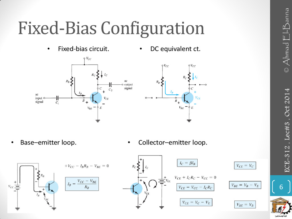
Fixed-Bias Configuration 6 ECE-312 , Lec#3 , Oct 2014 •
Fixed-bias circuit. • DC equivalent ct. • Base–emitter loop. • Collector–emitter loop. © Ahmad El-Banna
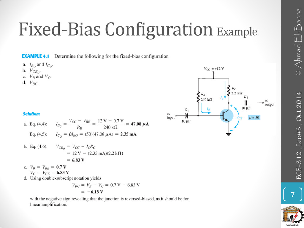
Fixed-Bias Configuration Example 7 ECE-312 , Lec#3 , Oct 2014
© Ahmad El-Banna
Fixed-Bias Configuration ... • Transistor Saturation 8 ECE-312 , Lec#3
, Oct 2014 • Determining ICsat for the fixed-bias configuration. • Determining ICsat • Saturation regions: (a) Actual (b) approximate. © Ahmad El-Banna
Fixed-Bias Configuration ... 9 ECE-312 , Lec#3 , Oct 2014
• Load Line Analysis © Ahmad El-Banna
Emitter-Bias Configuration 10 ECE-312 , Lec#3 , Oct 2014 •
Base-Emitter Loop • DC equivalent ct • BJT bias circuit with emitter resistor. © Ahmad El-Banna
Emitter-Bias Configuration 11 ECE-312 , Lec#3 , Oct 2014 Collector-Emitter
Loop © Ahmad El-Banna
Emitter-Bias Configuration • Improved bias stability (check example 4.5) 12
ECE-312 , Lec#3 , Oct 2014 The addition of the emitter resistor to the dc bias of the BJT provides improved stability, that is, the dc bias currents and voltages remain closer to where they were set by the circuit when outside conditions, such as temperature and transistor beta, change. • Saturation Level • Load Line Analysis © Ahmad El-Banna
Voltage-Divider Configuration 13 ECE-312 , Lec#3 , Oct 2014 •
Exact Analysis • Voltage-divider bias configuration. • DC components of the voltage-divider configuration. © Ahmad El-Banna
Voltage-Divider Configuration 14 ECE-312 , Lec#3 , Oct 2014 •
Approximate Analysis • Transistor Saturation • Load-Line Analysis © Ahmad El-Banna
Voltage-Divider Configuration Example 15 ECE-312 , Lec#3 , Oct 2014
© Ahmad El-Banna
Collector Feedback Configuration 16 ECE-312 , Lec#3 , Oct 2014
• DC bias circuit with voltage feedback. • Base–Emitter Loop • Collector–Emitter Loop © Ahmad El-Banna
Collector Feedback Configuration 17 ECE-312 , Lec#3 , Oct 2014
• Saturation Conditions Using the approximation I’C = IC • Load-Line Analysis Continuing with the approximation I’C = IC results in the same load line defined for the voltage-divider and emitter-biased configurations. The level of IBQ is defined by the chosen bias configuration. © Ahmad El-Banna
Emitter-Follower Configuration 18 ECE-312 , Lec#3 , Oct 2014 i/p
ct o/p ct • dc equivalent ct • Common-collecter (emitter-follower) configuration. © Ahmad El-Banna
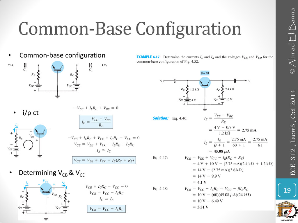
Common-Base Configuration 19 ECE-312 , Lec#3 , Oct 2014 •
i/p ct • Determining VCB & VCE • Common-base configuration © Ahmad El-Banna
MISCELLANEOUS BIAS CONFIGURATIONS 20 ECE-312 , Lec#3 , Oct 2014
© Ahmad El-Banna
Summary Table 21 ECE-312 , Lec#3 , Oct 2014 ©
Ahmad El-Banna
Summary Table.. 22 ECE-312 , Lec#3 , Oct 2014 ©
Ahmad El-Banna
DESIGN OPERATION 23 ECE-312 , Lec#3 , Oct 2014 ©
Ahmad El-Banna
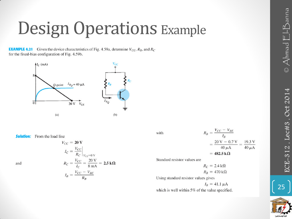
Design Operations 24 ECE-312 , Lec#3 , Oct 2014 •
Discussions thus far have focused on the analysis of existing networks. All the elements are in place, and it is simply a matter of solving for the current and voltage levels of the configuration. • The design process is one where a current and/or voltage may be specified and the elements required to establish the designated levels must be determined. • The design sequence is obviously sensitive to the components that are already specified and the elements to be determined. If the transistor and supplies are specified, the design process will simply determine the required resistors for a particular design. • Once the theoretical values of the resistors are determined, the nearest standard commercial values are normally chosen and any variations due to not using the exact resistance values are accepted as part of the design. © Ahmad El-Banna
Design Operations Example 25 ECE-312 , Lec#3 , Oct 2014
© Ahmad El-Banna
Design Operations Example.. 26 ECE-312 , Lec#3 , Oct 2014
• Design of a Current-Gain-Stabilized (Beta-Independent) Circuit © Ahmad El-Banna
VARIOUS BJT CIRCUITS • MULTIPLE BJT NETWORKS • CURRENT MIRRORS
• CURRENT SOURCE CIRCUITS • Bipolar Transistor Constant-Current Source • Transistor/Zener Constant-Current Source • PNP TRANSISTORS • TRANSISTOR SWITCHING NETWORKS 27 ECE-312 , Lec#3 , Oct 2014 © Ahmad El-Banna
MULTIPLE BJT NETWORKS 28 ECE-312 , Lec#3 , Oct 2014
• R–C coupling • Darlington configuration © Ahmad El-Banna
MULTIPLE BJT NETWORKS.. 29 ECE-312 , Lec#3 , Oct 2014
© Ahmad El-Banna
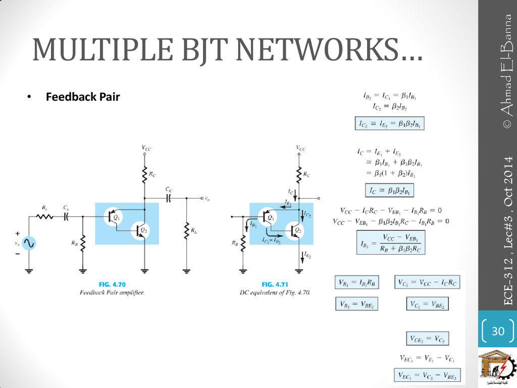
MULTIPLE BJT NETWORKS… 30 ECE-312 , Lec#3 , Oct 2014
• Feedback Pair © Ahmad El-Banna
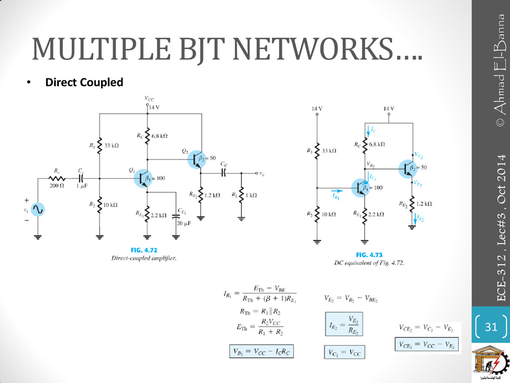
MULTIPLE BJT NETWORKS…. 31 ECE-312 , Lec#3 , Oct 2014
• Direct Coupled © Ahmad El-Banna
CURRENT MIRRORS 32 ECE-312 , Lec#3 , Oct 2014 ©
Ahmad El-Banna
CURRENT SOURCE CIRCUITS 33 ECE-312 , Lec#3 , Oct 2014
• Bipolar Transistor Constant-Current Source • Transistor/Zener Constant-Current Source © Ahmad El-Banna
pnp TRANSISTORS 34 ECE-312 , Lec#3 , Oct 2014 TRANSISTOR
SWITCHING NETWORKS © Ahmad El-Banna
TRANSISTOR SWITCHING NETWORKS.. 35 ECE-312 , Lec#3 , Oct 2014
© Ahmad El-Banna
TROUBLESHOOTING TECHNIQUES 36 ECE-312 , Lec#3 , Oct 2014 ©
Ahmad El-Banna
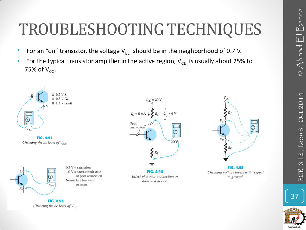
TROUBLESHOOTING TECHNIQUES • For an “on” transistor, the voltage VBE
should be in the neighborhood of 0.7 V. • For the typical transistor amplifier in the active region, VCE is usually about 25% to 75% of VCC . 37 ECE-312 , Lec#3 , Oct 2014 © Ahmad El-Banna
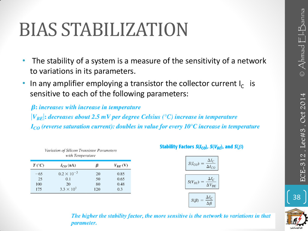
BIAS STABILIZATION • The stability of a system is a
measure of the sensitivity of a network to variations in its parameters. • In any amplifier employing a transistor the collector current IC is sensitive to each of the following parameters: 38 ECE-312 , Lec#3 , Oct 2014 © Ahmad El-Banna
BIAS STABILIZATION .. S(I co ) 39 ECE-312 , Lec#3
, Oct 2014 • fixed-bias configuration the level of IC would continue to rise with temperature, with IB maintaining a fairly constant value—a very unstable situation. • emitter-bias configuration there is a reaction to an increase in IC that will tend to oppose the change in bias conditions. • feedback configuration a stabilizing effect as described for the emitter-bias configuration. • voltage-divider bias The most stable of the configurations © Ahmad El-Banna
BIAS STABILIZATION .. S(V BE )& S(β) 40 ECE-312 ,
Lec#3 , Oct 2014 For fixed-bias © Ahmad El-Banna
PRACTICAL APPLICATION • BJT Diode Usage and Protective Capabilities •
Relay Driver • Light Control • Maintaining a Fixed Load Current • Alarm System with a CCS • Voltage Level Indicator • Logic Gates 41 ECE-312 , Lec#3 , Oct 2014 © Ahmad El-Banna
Practical Application 42 ECE-312 , Lec#3 , Oct 2014 •
BJT Diode Usage and Protective Capabilities • Relay Driver © Ahmad El-Banna
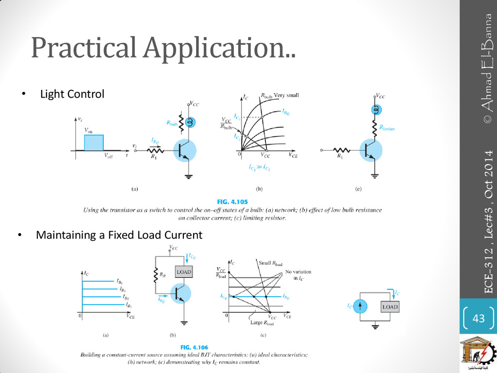
Practical Application.. 43 ECE-312 , Lec#3 , Oct 2014 •
Maintaining a Fixed Load Current • Light Control © Ahmad El-Banna
Practical Application… 44 ECE-312 , Lec#3 , Oct 2014 •
Alarm System with a CCS • Voltage Level Indicator © Ahmad El-Banna
Practical Application…. 45 ECE-312 , Lec#3 , Oct 2014 •
Logic Gates © Ahmad El-Banna
• For more details, refer to: • Chapter 4 at
R. Boylestad, Electronic Devices and Circuit Theory, 11th edition, Prentice Hall. • The lecture is available online at: • https://speakerdeck.com/ahmad_elbanna • For inquires, send to: •
[email protected]
•
[email protected]
46 ECE-312 , Lec#3 , Oct 2014 © Ahmad El-Banna