fiddling around with microelectronics but later developed an interest in telecommunications while debugging a problem. Well, it’s been about 14 years since that incident. • I’m a consultant working with private companies that prefer to keep their networks obscure and safe from the prying eyes of internet predators and paedophiles. • I spend my time researching and testing around Layer 1 to Layer 4 stuffs and fiddling with their security if and when time permits. • Sometimes, I volunteer my time to organisations working on causes I believe in. • I am a student pilot with 16 flying hours logged in a Cessna 172SP. • I have a pet cat who, whenever I say “pspsps,” replies with a “meow.”
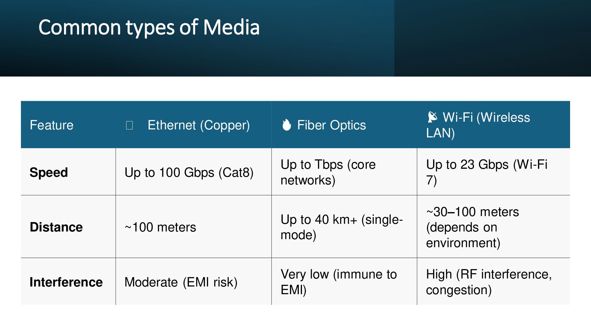
Optics 📡 Wi-Fi (Wireless LAN) Speed Up to 100 Gbps (Cat8) Up to Tbps (core networks) Up to 23 Gbps (Wi-Fi 7) Distance ~100 meters Up to 40 km+ (single- mode) ~30–100 meters (depends on environment) Interference Moderate (EMI risk) Very low (immune to EMI) High (RF interference, congestion)
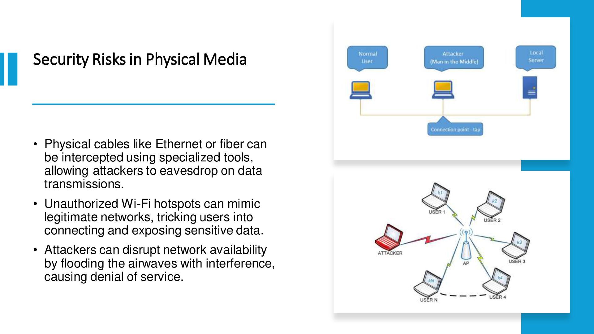
or fiber can be intercepted using specialized tools, allowing attackers to eavesdrop on data transmissions. • Unauthorized Wi-Fi hotspots can mimic legitimate networks, tricking users into connecting and exposing sensitive data. • Attackers can disrupt network availability by flooding the airwaves with interference, causing denial of service.
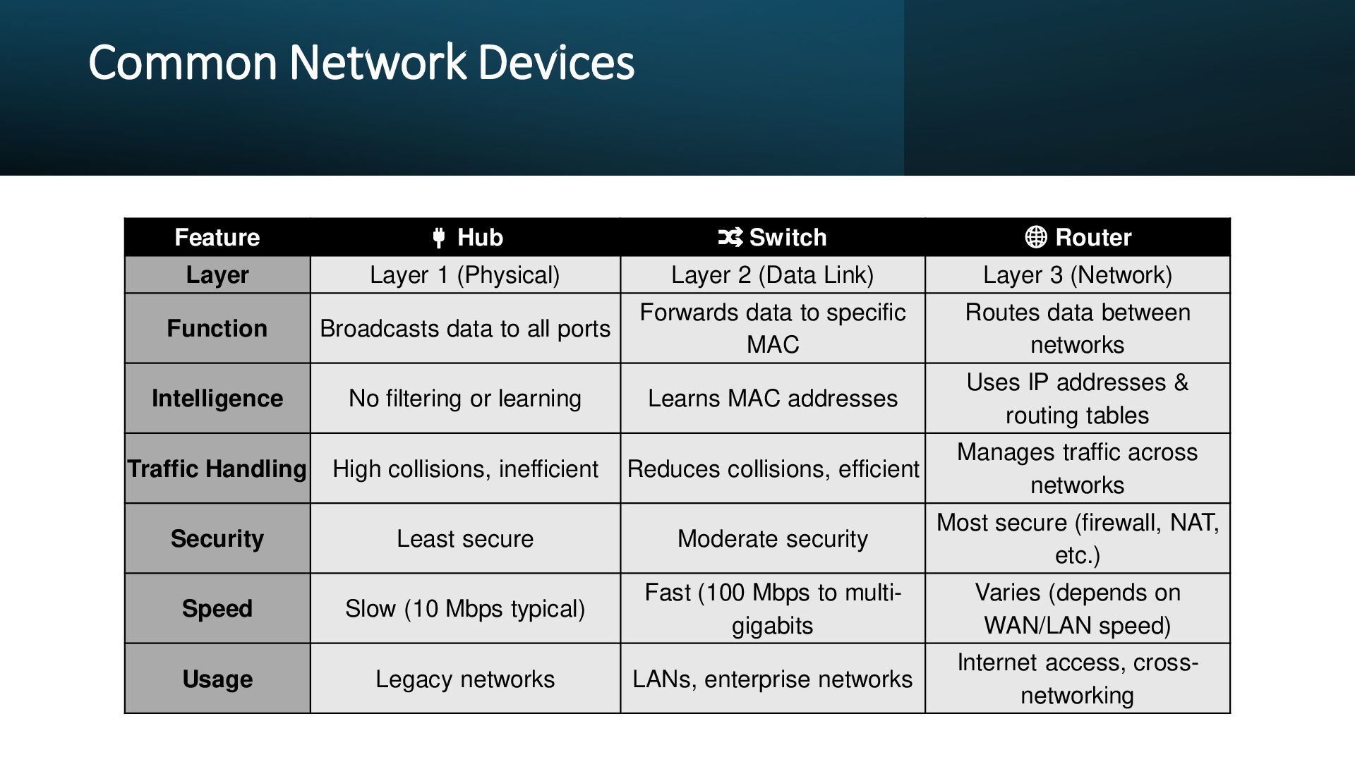
Layer Layer 1 (Physical) Layer 2 (Data Link) Layer 3 (Network) Function Broadcasts data to all ports Forwards data to specific MAC Routes data between networks Intelligence No filtering or learning Learns MAC addresses Uses IP addresses & routing tables Traffic Handling High collisions, inefficient Reduces collisions, efficient Manages traffic across networks Security Least secure Moderate security Most secure (firewall, NAT, etc.) Speed Slow (10 Mbps typical) Fast (100 Mbps to multi- gigabits Varies (depends on WAN/LAN speed) Usage Legacy networks LANs, enterprise networks Internet access, cross- networking
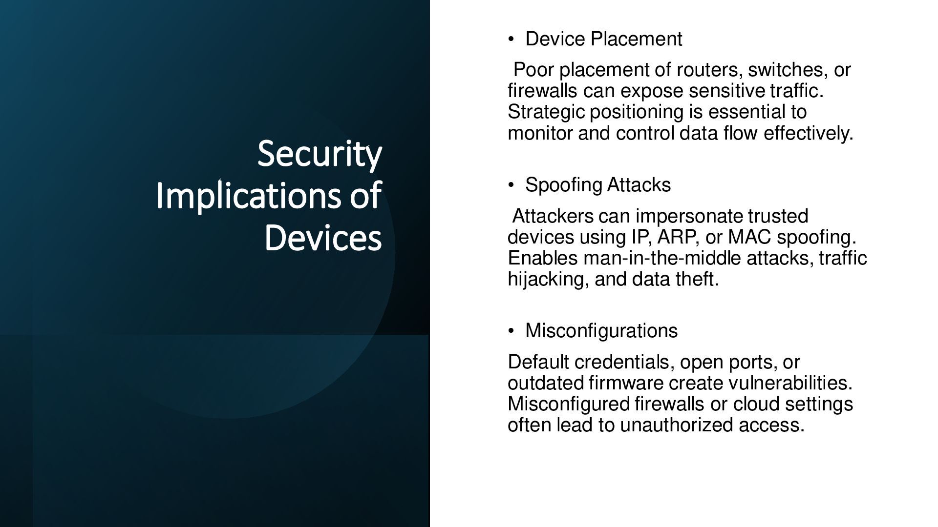
routers, switches, or firewalls can expose sensitive traffic. Strategic positioning is essential to monitor and control data flow effectively. • Spoofing Attacks Attackers can impersonate trusted devices using IP, ARP, or MAC spoofing. Enables man-in-the-middle attacks, traffic hijacking, and data theft. • Misconfigurations Default credentials, open ports, or outdated firmware create vulnerabilities. Misconfigured firewalls or cloud settings often lead to unauthorized access.
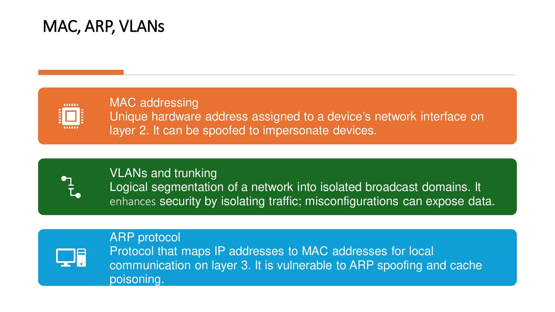
a device’s network interface on layer 2. It can be spoofed to impersonate devices. VLANs and trunking Logical segmentation of a network into isolated broadcast domains. It enhances security by isolating traffic; misconfigurations can expose data. ARP protocol Protocol that maps IP addresses to MAC addresses for local communication on layer 3. It is vulnerable to ARP spoofing and cache poisoning.
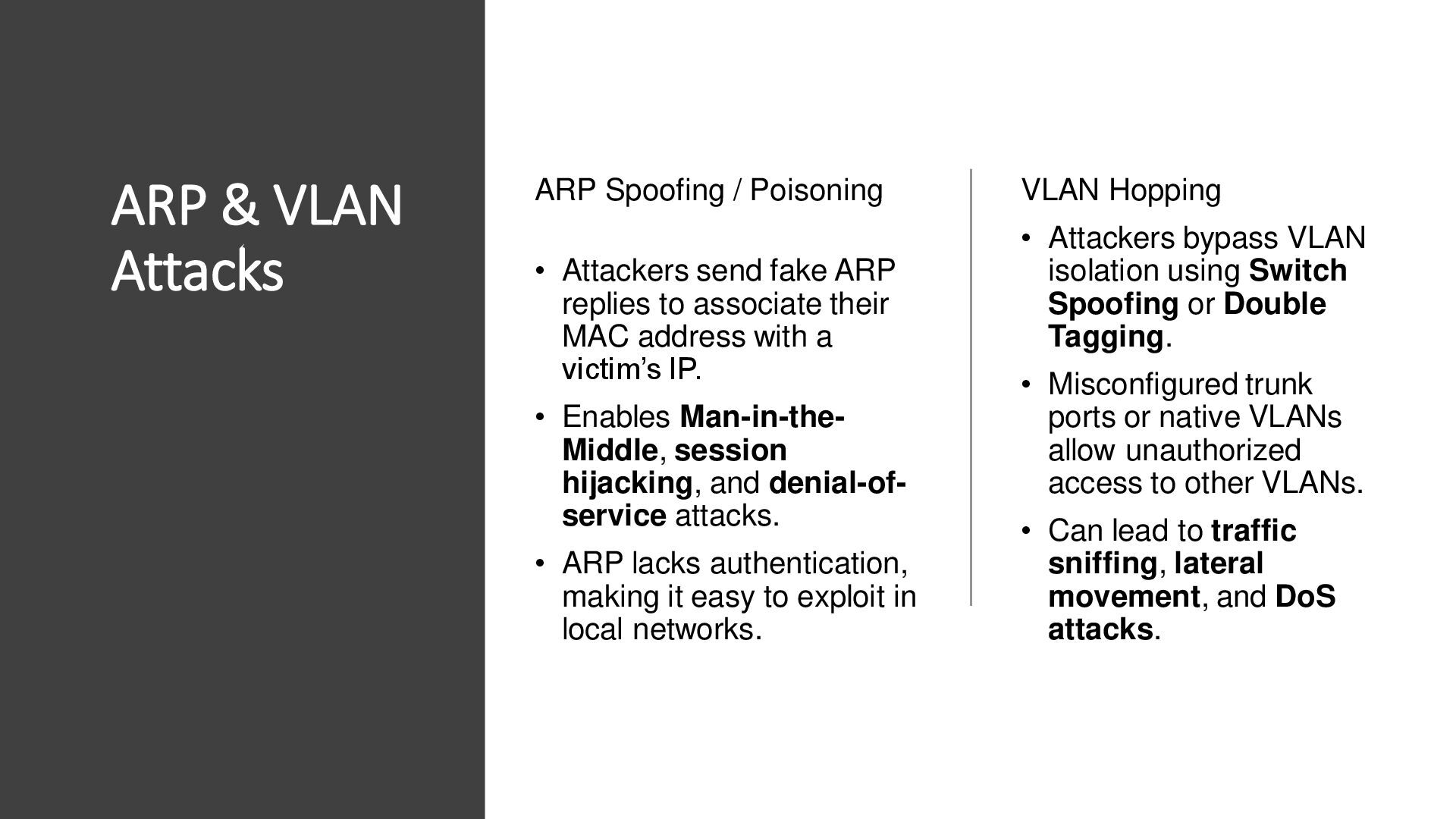
send fake ARP replies to associate their MAC address with a victim’s IP. • Enables Man-in-the- Middle, session hijacking, and denial-of- service attacks. • ARP lacks authentication, making it easy to exploit in local networks. VLAN Hopping • Attackers bypass VLAN isolation using Switch Spoofing or Double Tagging. • Misconfigured trunk ports or native VLANs allow unauthorized access to other VLANs. • Can lead to traffic sniffing, lateral movement, and DoS attacks.
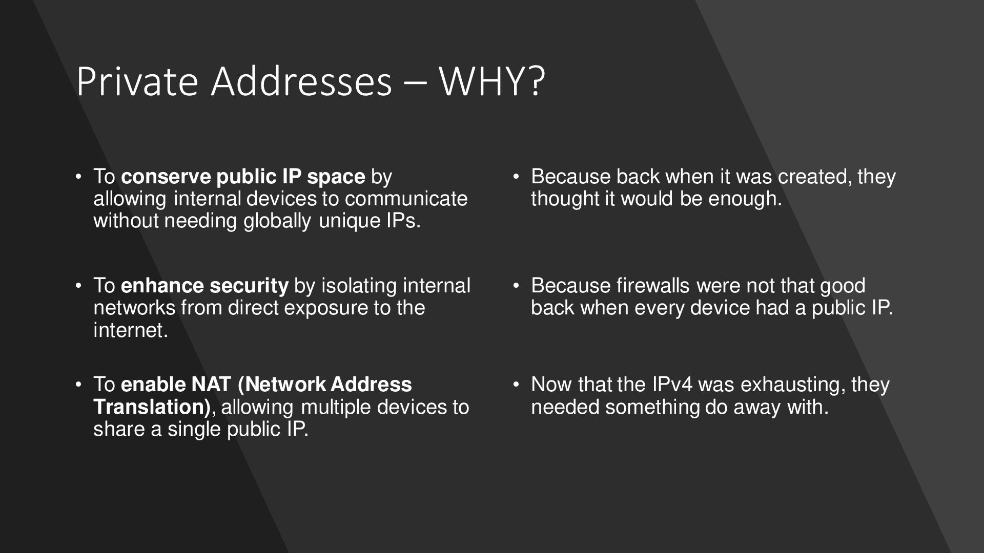
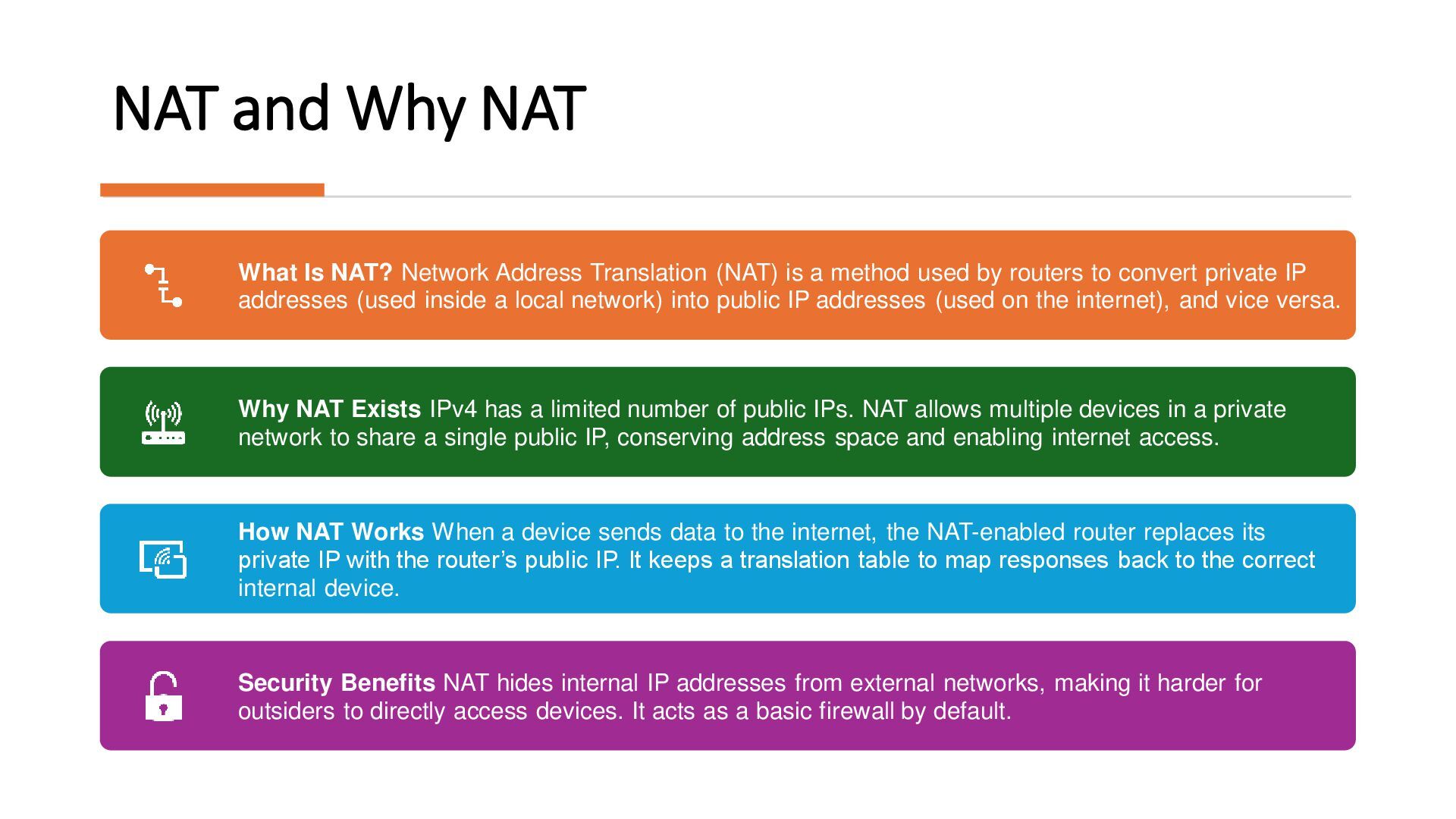
by allowing internal devices to communicate without needing globally unique IPs. • To enhance security by isolating internal networks from direct exposure to the internet. • To enable NAT (Network Address Translation), allowing multiple devices to share a single public IP. • Because back when it was created, they thought it would be enough. • Because firewalls were not that good back when every device had a public IP. • Now that the IPv4 was exhausting, they needed something do away with.
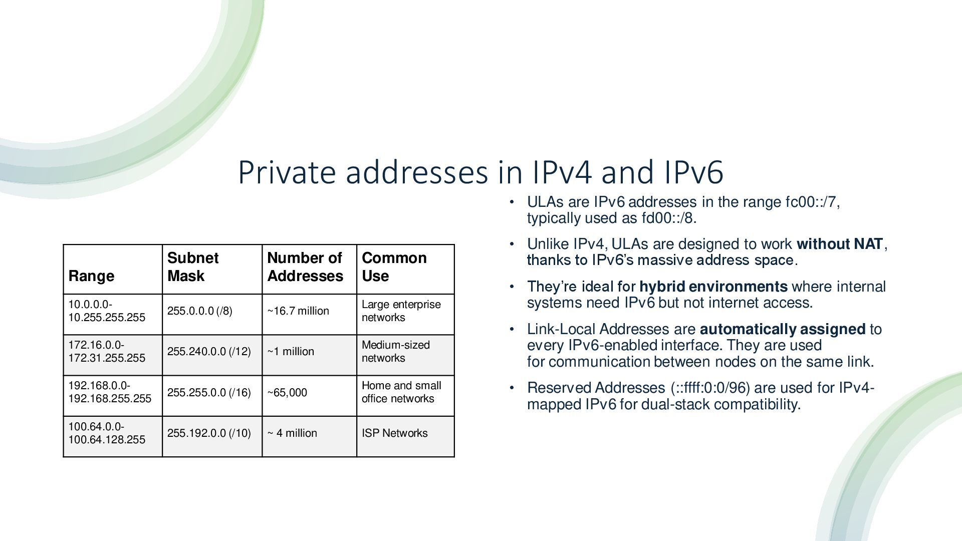
addresses in the range fc00::/7, typically used as fd00::/8. • Unlike IPv4, ULAs are designed to work without NAT, thanks to IPv6’s massive address space. • They’re ideal for hybrid environments where internal systems need IPv6 but not internet access. • Link-Local Addresses are automatically assigned to every IPv6-enabled interface. They are used for communication between nodes on the same link. • Reserved Addresses (::ffff:0:0/96) are used for IPv4- mapped IPv6 for dual-stack compatibility. Range Subnet Mask Number of Addresses Common Use 10.0.0.0- 10.255.255.255 255.0.0.0 (/8) ~16.7 million Large enterprise networks 172.16.0.0- 172.31.255.255 255.240.0.0 (/12) ~1 million Medium-sized networks 192.168.0.0- 192.168.255.255 255.255.0.0 (/16) ~65,000 Home and small office networks 100.64.0.0- 100.64.128.255 255.192.0.0 (/10) ~ 4 million ISP Networks
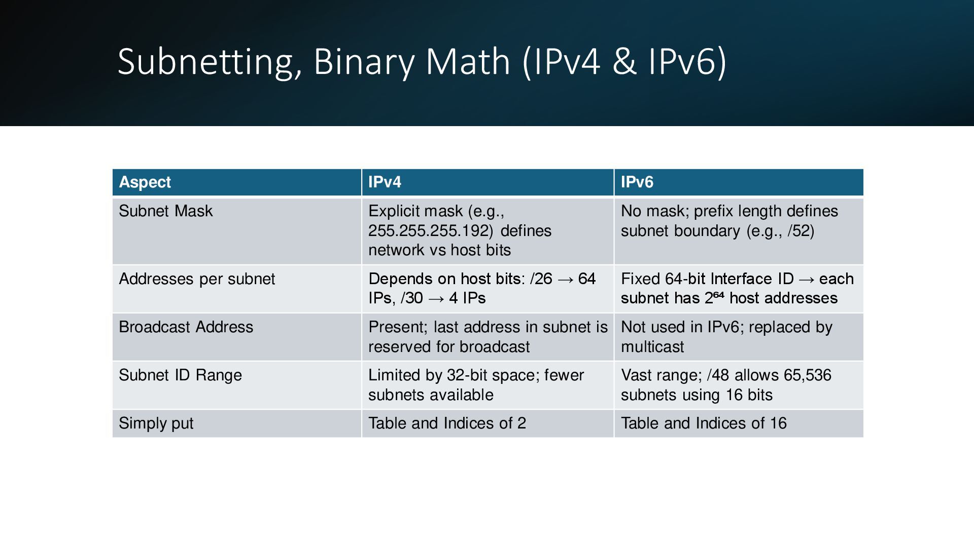
Mask Explicit mask (e.g., 255.255.255.192) defines network vs host bits No mask; prefix length defines subnet boundary (e.g., /52) Addresses per subnet Depends on host bits: /26 → 64 IPs, /30 → 4 IPs Fixed 64-bit Interface ID → each subnet has 2⁶⁴ host addresses Broadcast Address Present; last address in subnet is reserved for broadcast Not used in IPv6; replaced by multicast Subnet ID Range Limited by 32-bit space; fewer subnets available Vast range; /48 allows 65,536 subnets using 16 bits Simply put Table and Indices of 2 Table and Indices of 16
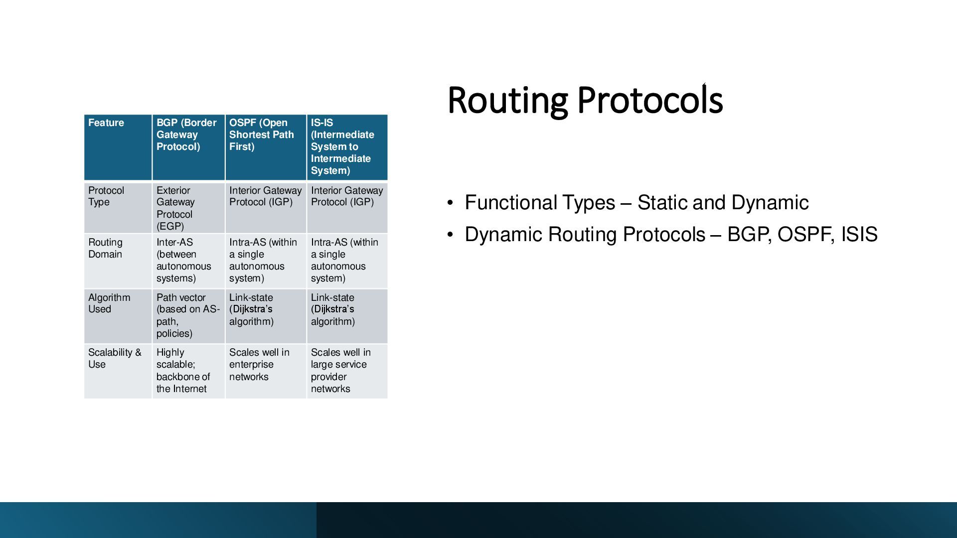
Dynamic Routing Protocols – BGP, OSPF, ISIS Feature BGP (Border Gateway Protocol) OSPF (Open Shortest Path First) IS-IS (Intermediate System to Intermediate System) Protocol Type Exterior Gateway Protocol (EGP) Interior Gateway Protocol (IGP) Interior Gateway Protocol (IGP) Routing Domain Inter-AS (between autonomous systems) Intra-AS (within a single autonomous system) Intra-AS (within a single autonomous system) Algorithm Used Path vector (based on AS- path, policies) Link-state (Dijkstra’s algorithm) Link-state (Dijkstra’s algorithm) Scalability & Use Highly scalable; backbone of the Internet Scales well in enterprise networks Scales well in large service provider networks
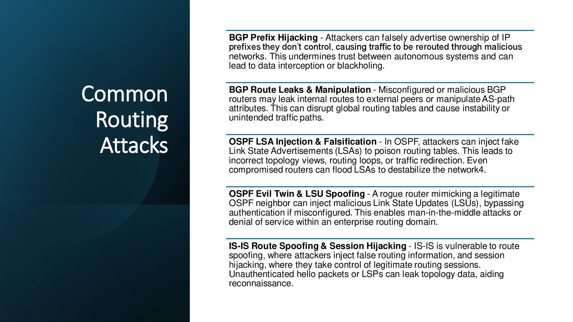
advertise ownership of IP prefixes they don’t control, causing traffic to be rerouted through malicious networks. This undermines trust between autonomous systems and can lead to data interception or blackholing. BGP Route Leaks & Manipulation - Misconfigured or malicious BGP routers may leak internal routes to external peers or manipulate AS-path attributes. This can disrupt global routing tables and cause instability or unintended traffic paths. OSPF LSA Injection & Falsification - In OSPF, attackers can inject fake Link State Advertisements (LSAs) to poison routing tables. This leads to incorrect topology views, routing loops, or traffic redirection. Even compromised routers can flood LSAs to destabilize the network4. OSPF Evil Twin & LSU Spoofing - A rogue router mimicking a legitimate OSPF neighbor can inject malicious Link State Updates (LSUs), bypassing authentication if misconfigured. This enables man-in-the-middle attacks or denial of service within an enterprise routing domain. IS-IS Route Spoofing & Session Hijacking - IS-IS is vulnerable to route spoofing, where attackers inject false routing information, and session hijacking, where they take control of legitimate routing sessions. Unauthenticated hello packets or LSPs can leak topology data, aiding reconnaissance.
(NAT) is a method used by routers to convert private IP addresses (used inside a local network) into public IP addresses (used on the internet), and vice versa. Why NAT Exists IPv4 has a limited number of public IPs. NAT allows multiple devices in a private network to share a single public IP, conserving address space and enabling internet access. How NAT Works When a device sends data to the internet, the NAT-enabled router replaces its private IP with the router’s public IP. It keeps a translation table to map responses back to the correct internal device. Security Benefits NAT hides internal IP addresses from external networks, making it harder for outsiders to directly access devices. It acts as a basic firewall by default.
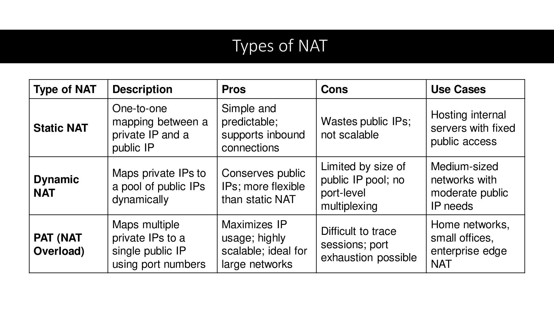
Cases Static NAT One-to-one mapping between a private IP and a public IP Simple and predictable; supports inbound connections Wastes public IPs; not scalable Hosting internal servers with fixed public access Dynamic NAT Maps private IPs to a pool of public IPs dynamically Conserves public IPs; more flexible than static NAT Limited by size of public IP pool; no port-level multiplexing Medium-sized networks with moderate public IP needs PAT (NAT Overload) Maps multiple private IPs to a single public IP using port numbers Maximizes IP usage; highly scalable; ideal for large networks Difficult to trace sessions; port exhaustion possible Home networks, small offices, enterprise edge NAT
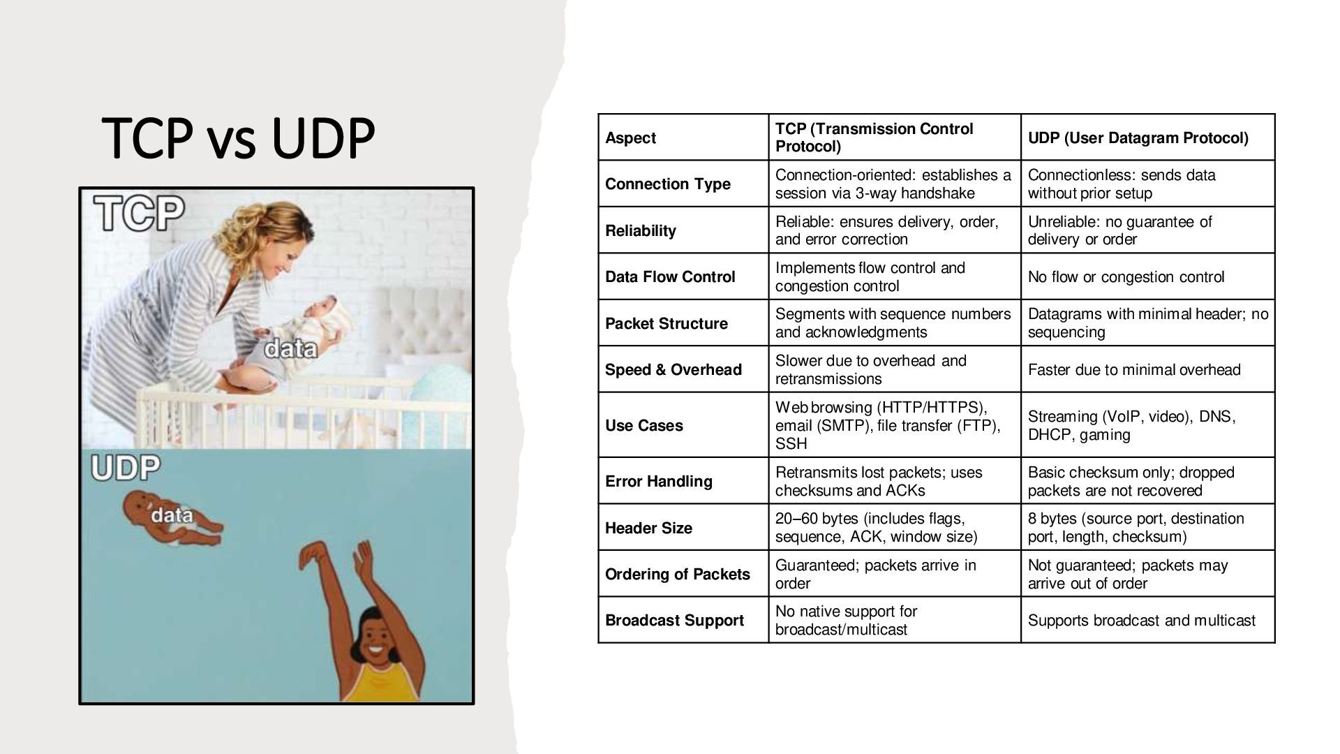
Datagram Protocol) Connection Type Connection-oriented: establishes a session via 3-way handshake Connectionless: sends data without prior setup Reliability Reliable: ensures delivery, order, and error correction Unreliable: no guarantee of delivery or order Data Flow Control Implements flow control and congestion control No flow or congestion control Packet Structure Segments with sequence numbers and acknowledgments Datagrams with minimal header; no sequencing Speed & Overhead Slower due to overhead and retransmissions Faster due to minimal overhead Use Cases Web browsing (HTTP/HTTPS), email (SMTP), file transfer (FTP), SSH Streaming (VoIP, video), DNS, DHCP, gaming Error Handling Retransmits lost packets; uses checksums and ACKs Basic checksum only; dropped packets are not recovered Header Size 20–60 bytes (includes flags, sequence, ACK, window size) 8 bytes (source port, destination port, length, checksum) Ordering of Packets Guaranteed; packets arrive in order Not guaranteed; packets may arrive out of order Broadcast Support No native support for broadcast/multicast Supports broadcast and multicast
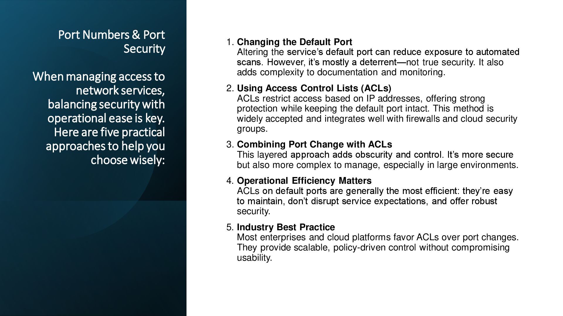
services, balancing security with operational ease is key. Here are five practical approaches to help you choose wisely: 1. Changing the Default Port Altering the service’s default port can reduce exposure to automated scans. However, it’s mostly a deterrent—not true security. It also adds complexity to documentation and monitoring. 2. Using Access Control Lists (ACLs) ACLs restrict access based on IP addresses, offering strong protection while keeping the default port intact. This method is widely accepted and integrates well with firewalls and cloud security groups. 3. Combining Port Change with ACLs This layered approach adds obscurity and control. It’s more secure but also more complex to manage, especially in large environments. 4. Operational Efficiency Matters ACLs on default ports are generally the most efficient: they’re easy to maintain, don’t disrupt service expectations, and offer robust security. 5. Industry Best Practice Most enterprises and cloud platforms favor ACLs over port changes. They provide scalable, policy-driven control without compromising usability.
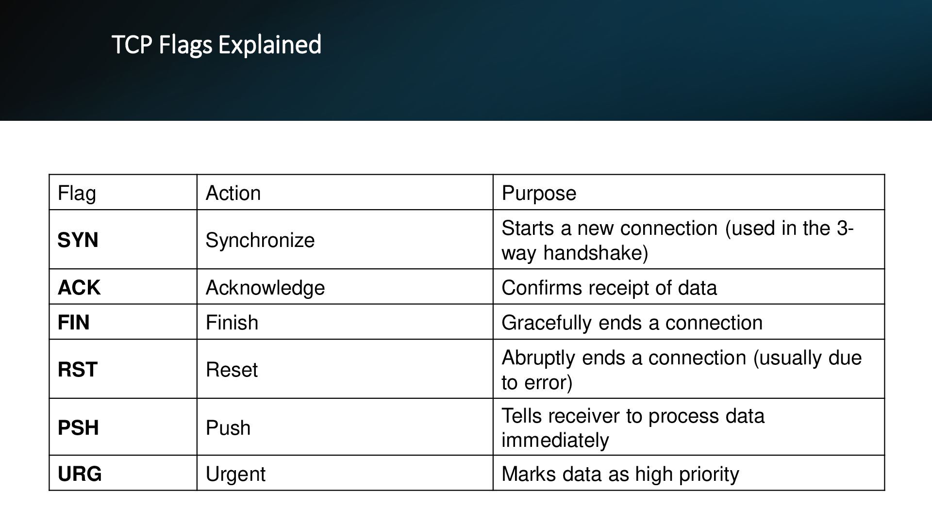
new connection (used in the 3- way handshake) ACK Acknowledge Confirms receipt of data FIN Finish Gracefully ends a connection RST Reset Abruptly ends a connection (usually due to error) PSH Push Tells receiver to process data immediately URG Urgent Marks data as high priority
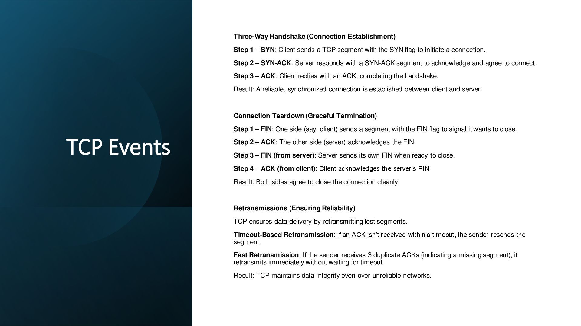
Client sends a TCP segment with the SYN flag to initiate a connection. Step 2 – SYN-ACK: Server responds with a SYN-ACK segment to acknowledge and agree to connect. Step 3 – ACK: Client replies with an ACK, completing the handshake. Result: A reliable, synchronized connection is established between client and server. Connection Teardown (Graceful Termination) Step 1 – FIN: One side (say, client) sends a segment with the FIN flag to signal it wants to close. Step 2 – ACK: The other side (server) acknowledges the FIN. Step 3 – FIN (from server): Server sends its own FIN when ready to close. Step 4 – ACK (from client): Client acknowledges the server’s FIN. Result: Both sides agree to close the connection cleanly. Retransmissions (Ensuring Reliability) TCP ensures data delivery by retransmitting lost segments. Timeout-Based Retransmission: If an ACK isn’t received within a timeout, the sender resends the segment. Fast Retransmission: If the sender receives 3 duplicate ACKs (indicating a missing segment), it retransmits immediately without waiting for timeout. Result: TCP maintains data integrity even over unreliable networks.
a connection before sending data. It simply sends packets (called datagrams) without checking if the receiver is ready or even available. There’s no handshake, no session tracking, and no acknowledgment. 2. No Reliability Mechanisms Unlike TCP, UDP does not guarantee delivery, order, or error correction. If packets are lost, duplicated, or arrive out of order, UDP won’t fix it. The application must handle any recovery or reordering if needed. 3. Minimal Overhead UDP has a very small header (8 bytes) compared to TCP’s 20–60 bytes. This makes it faster and more efficient for time-sensitive tasks, especially where speed matters more than reliability. 4. Key Differences from TCP • TCP is connection-oriented, reliable, and ensures ordered delivery. • UDP is connectionless, faster, and suitable for real-time communication. • TCP is like a phone call; UDP is like sending a postcard—no confirmation, just fire and forget.
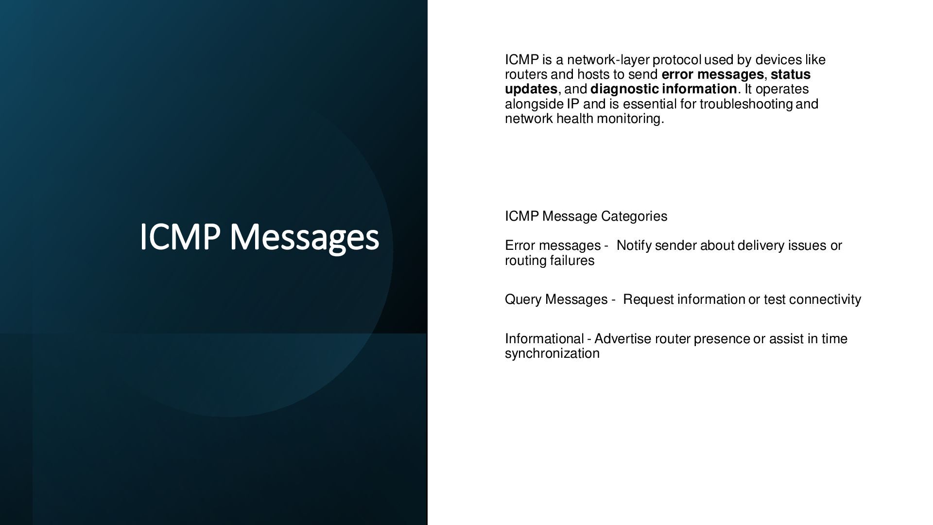
like routers and hosts to send error messages, status updates, and diagnostic information. It operates alongside IP and is essential for troubleshooting and network health monitoring. ICMP Message Categories Error messages - Notify sender about delivery issues or routing failures Query Messages - Request information or test connectivity Informational - Advertise router presence or assist in time synchronization
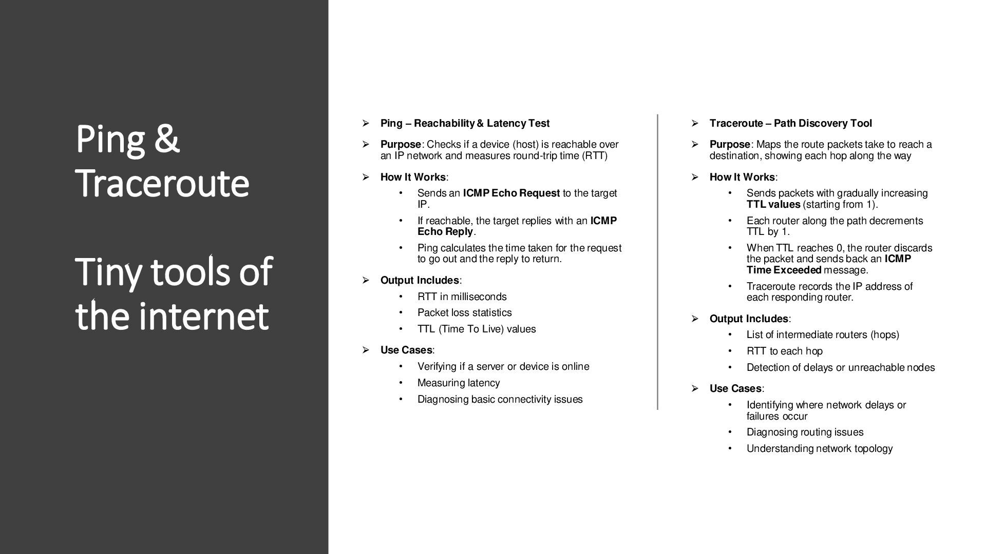
– Reachability & Latency Test Purpose: Checks if a device (host) is reachable over an IP network and measures round-trip time (RTT) How It Works: • Sends an ICMP Echo Request to the target IP. • If reachable, the target replies with an ICMP Echo Reply. • Ping calculates the time taken for the request to go out and the reply to return. Output Includes: • RTT in milliseconds • Packet loss statistics • TTL (Time To Live) values Use Cases: • Verifying if a server or device is online • Measuring latency • Diagnosing basic connectivity issues Traceroute – Path Discovery Tool Purpose: Maps the route packets take to reach a destination, showing each hop along the way How It Works: • Sends packets with gradually increasing TTL values (starting from 1). • Each router along the path decrements TTL by 1. • When TTL reaches 0, the router discards the packet and sends back an ICMP Time Exceeded message. • Traceroute records the IP address of each responding router. Output Includes: • List of intermediate routers (hops) • RTT to each hop • Detection of delays or unreachable nodes Use Cases: • Identifying where network delays or failures occur • Diagnosing routing issues • Understanding network topology
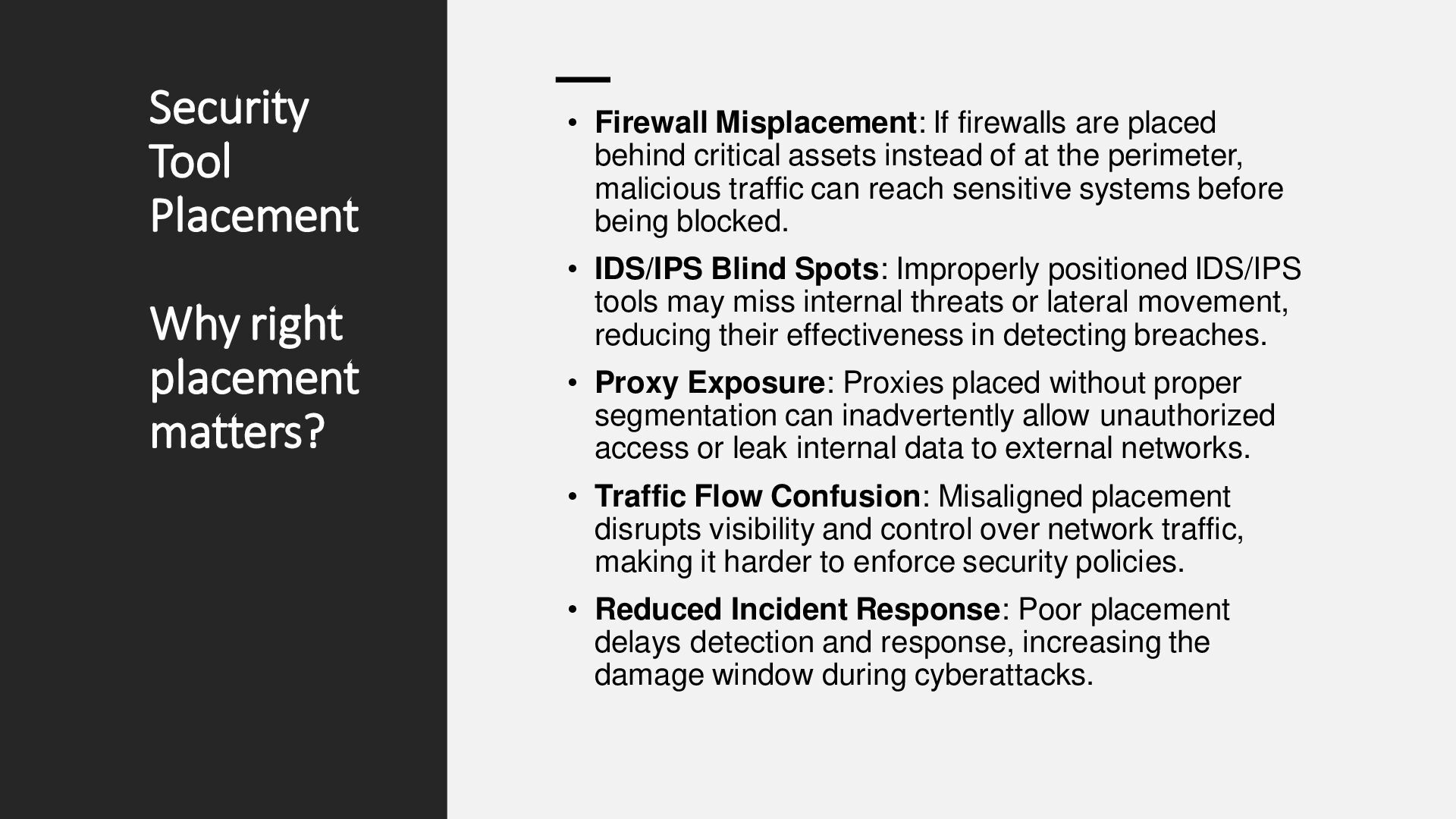
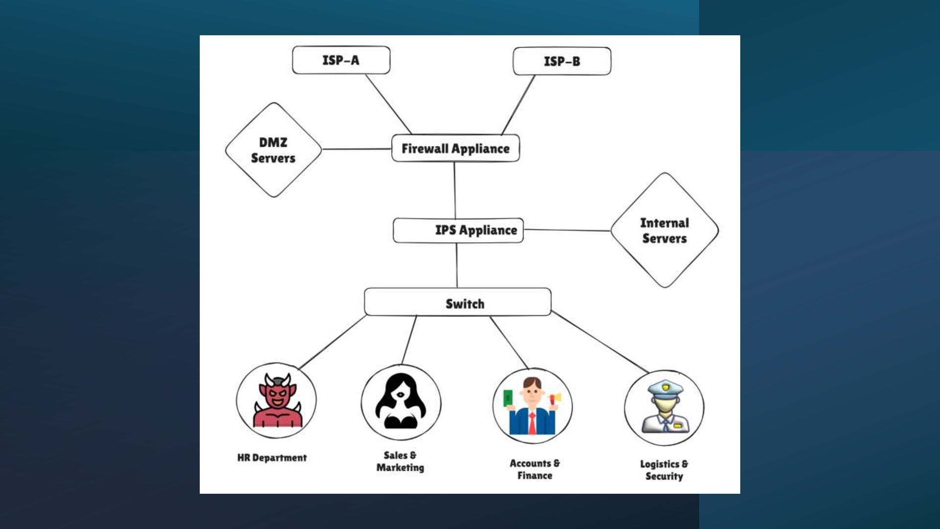
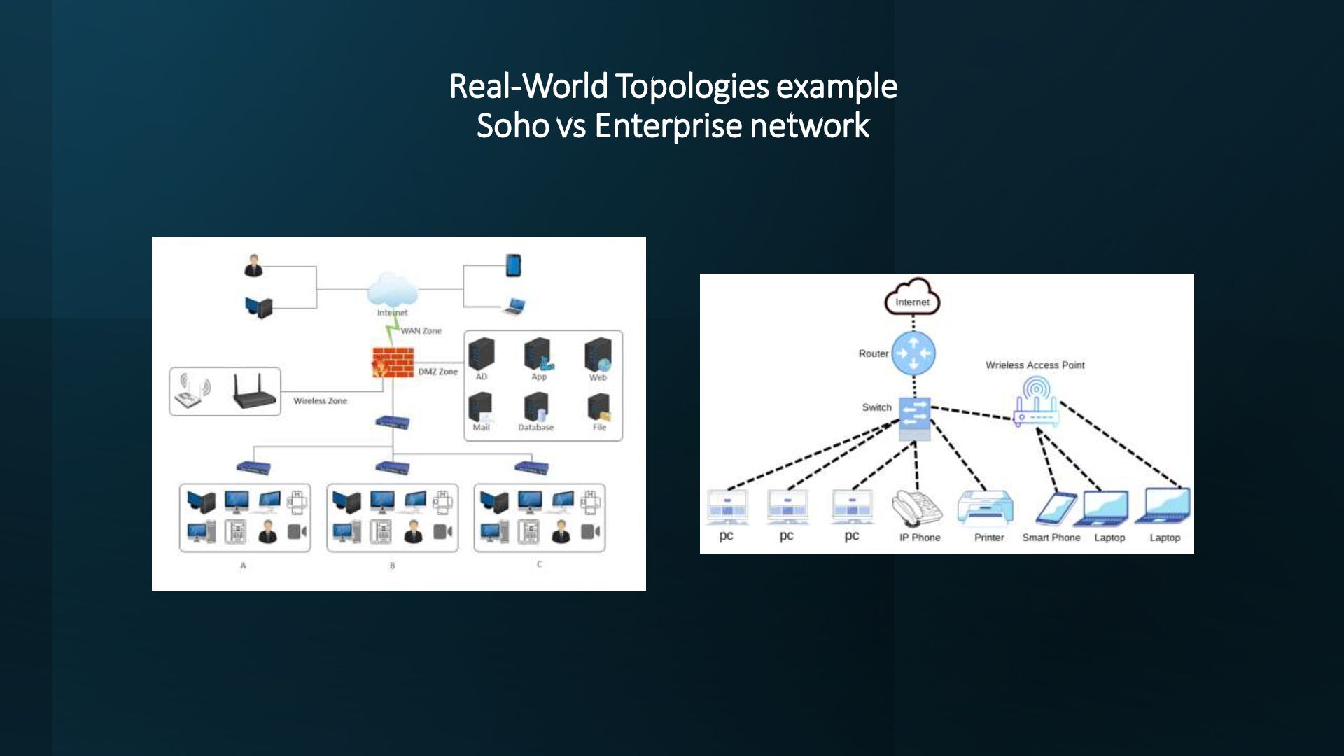
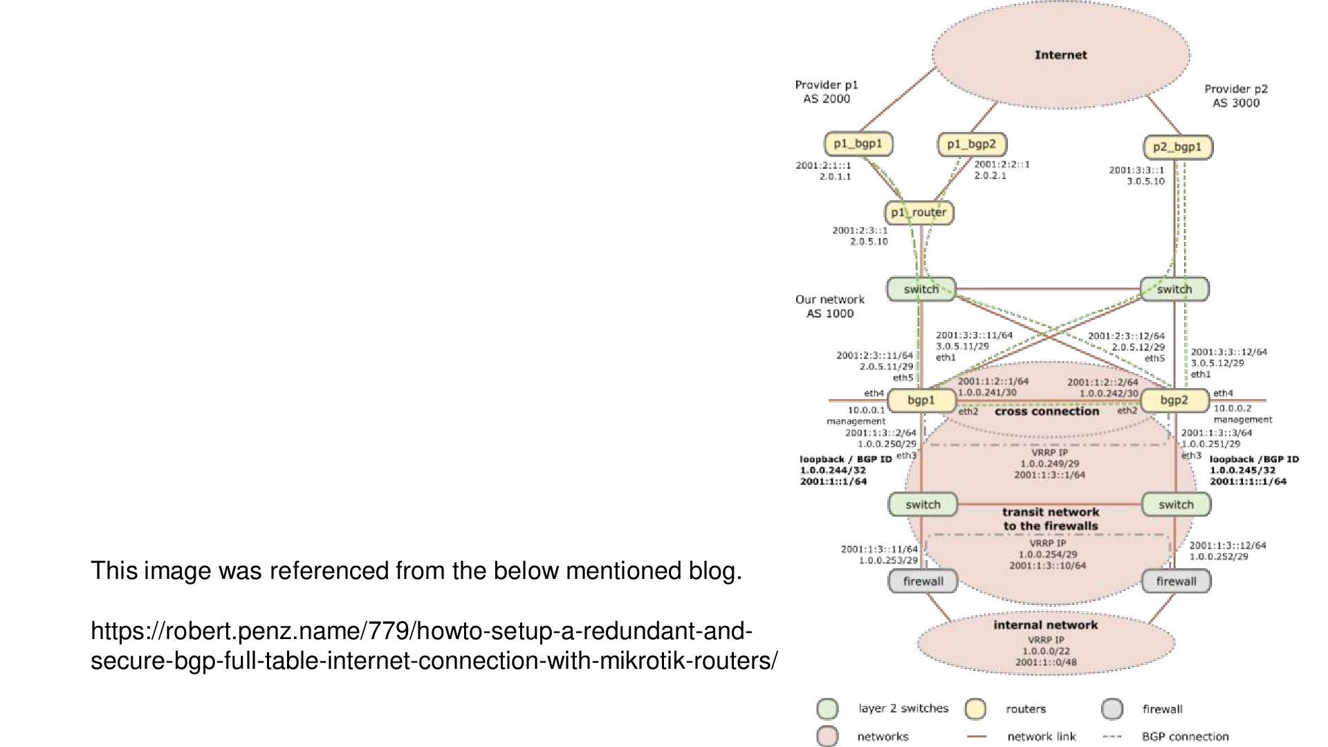
If firewalls are placed behind critical assets instead of at the perimeter, malicious traffic can reach sensitive systems before being blocked. • IDS/IPS Blind Spots: Improperly positioned IDS/IPS tools may miss internal threats or lateral movement, reducing their effectiveness in detecting breaches. • Proxy Exposure: Proxies placed without proper segmentation can inadvertently allow unauthorized access or leak internal data to external networks. • Traffic Flow Confusion: Misaligned placement disrupts visibility and control over network traffic, making it harder to enforce security policies. • Reduced Incident Response: Poor placement delays detection and response, increasing the damage window during cyberattacks.
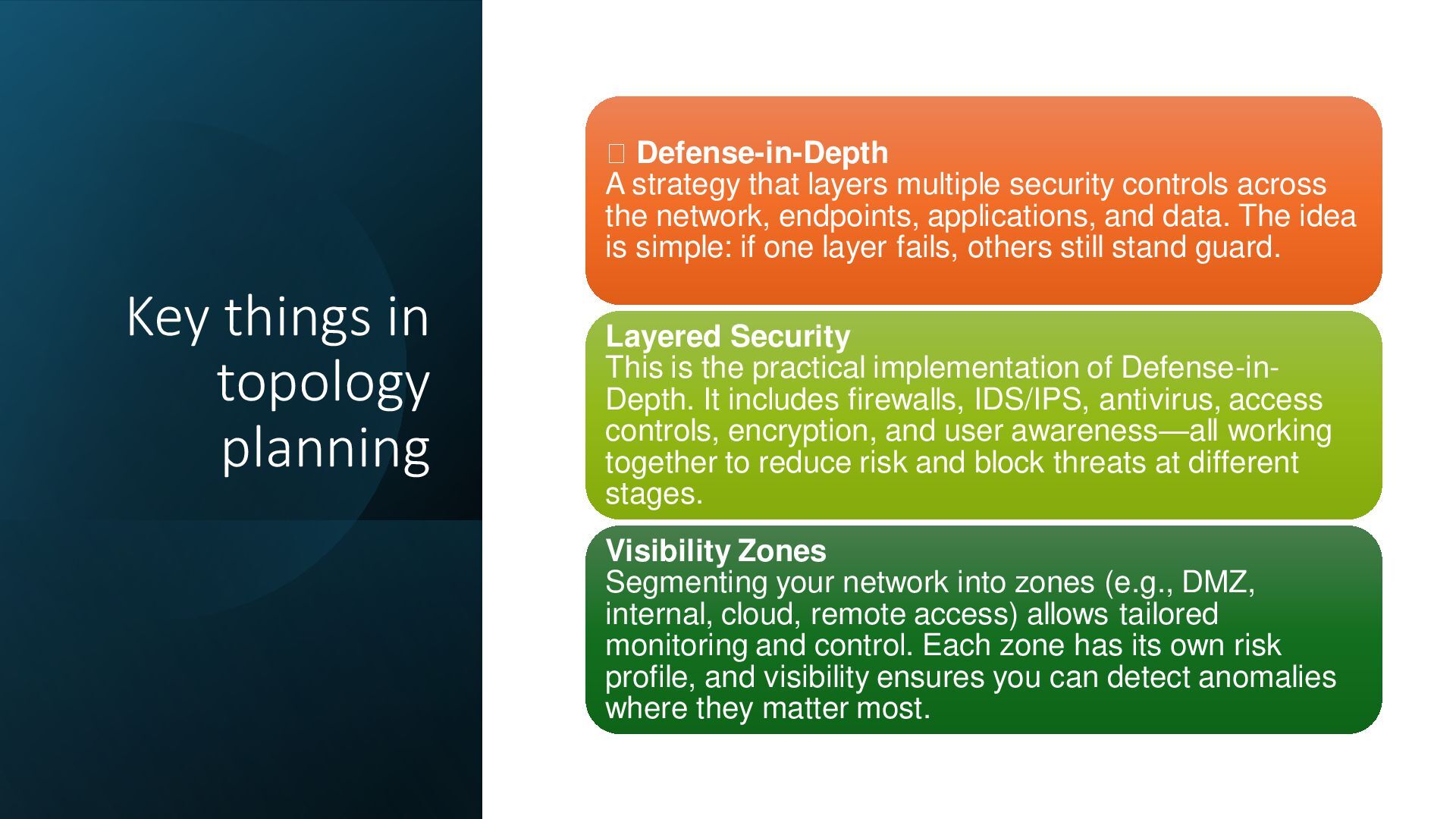
layers multiple security controls across the network, endpoints, applications, and data. The idea is simple: if one layer fails, others still stand guard. Layered Security This is the practical implementation of Defense-in- Depth. It includes firewalls, IDS/IPS, antivirus, access controls, encryption, and user awareness—all working together to reduce risk and block threats at different stages. Visibility Zones Segmenting your network into zones (e.g., DMZ, internal, cloud, remote access) allows tailored monitoring and control. Each zone has its own risk profile, and visibility ensures you can detect anomalies where they matter most.