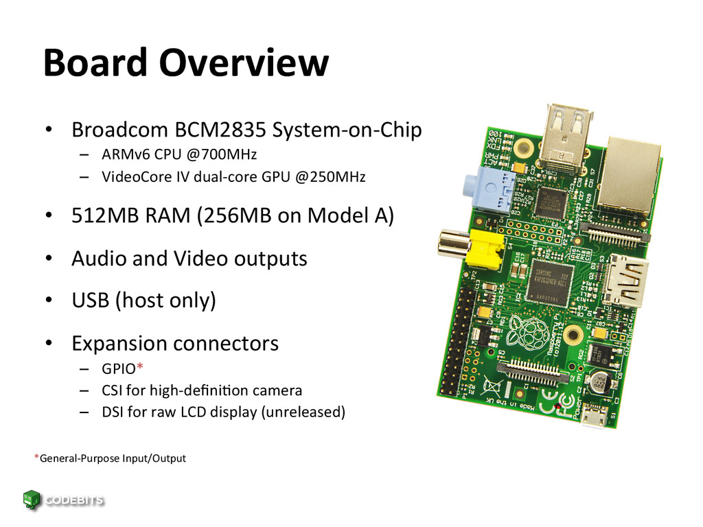
CPU @700MHz – VideoCore IV dual-‐core GPU @250MHz • 512MB RAM (256MB on Model A) • Audio and Video outputs • USB (host only) • Expansion connectors – GPIO* – CSI for high-‐definiFon camera – DSI for raw LCD display (unreleased) *General-‐Purpose Input/Output
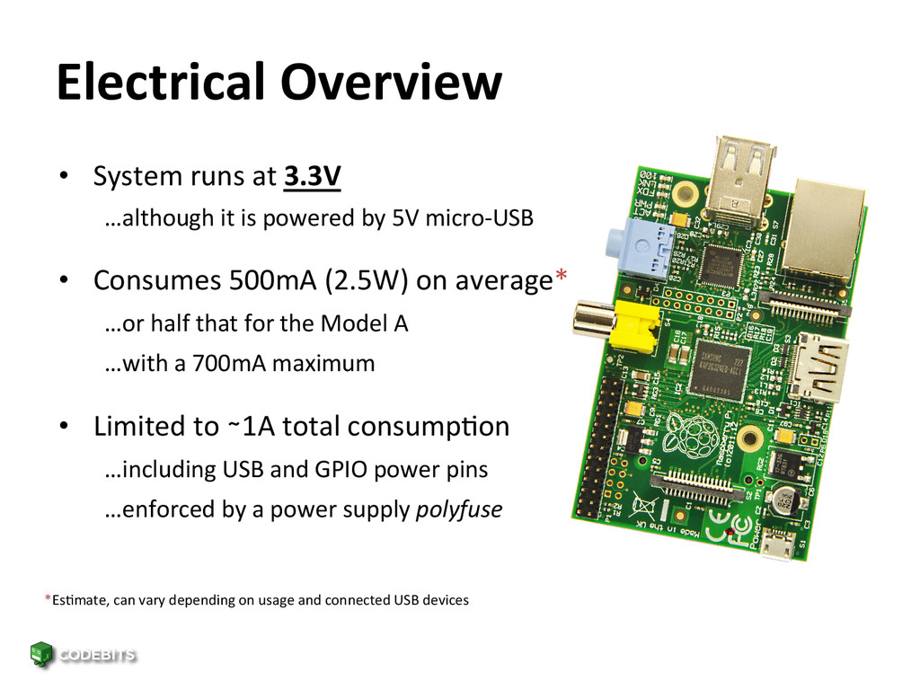
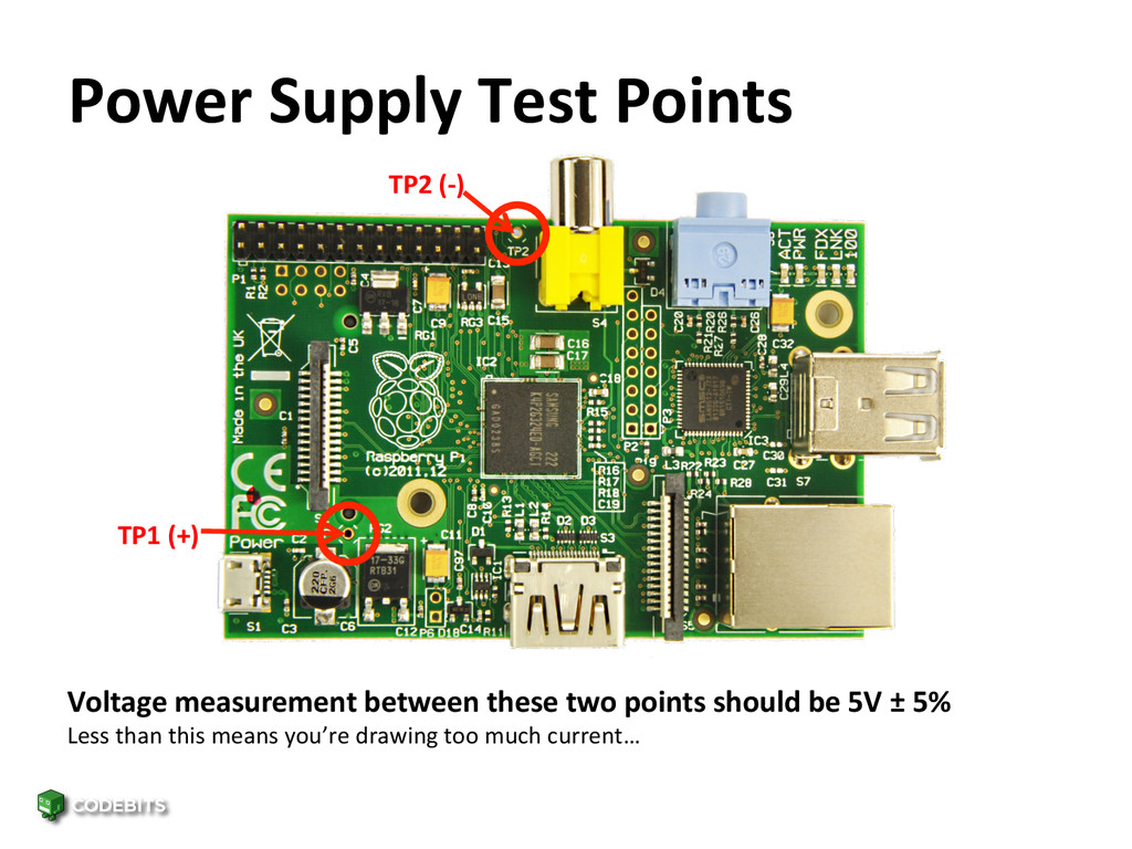
it is powered by 5V micro-‐USB • Consumes 500mA (2.5W) on average* …or half that for the Model A …with a 700mA maximum • Limited to ∼1A total consumpFon …including USB and GPIO power pins …enforced by a power supply polyfuse *EsFmate, can vary depending on usage and connected USB devices
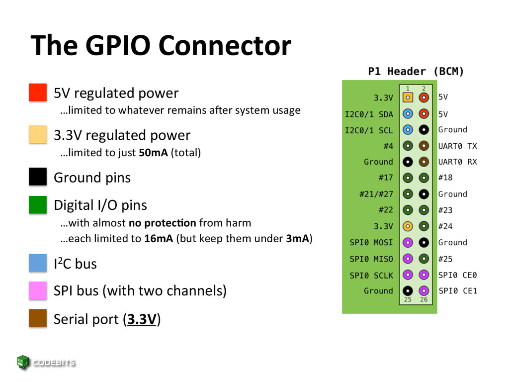
to whatever remains a_er system usage • 3.3V regulated power …limited to just 50mA (total) • Ground pins • Digital I/O pins …with almost no protec&on from harm …each limited to 16mA (but keep them under 3mA) • I2C bus • SPI bus (with two channels) • Serial port (3.3V)
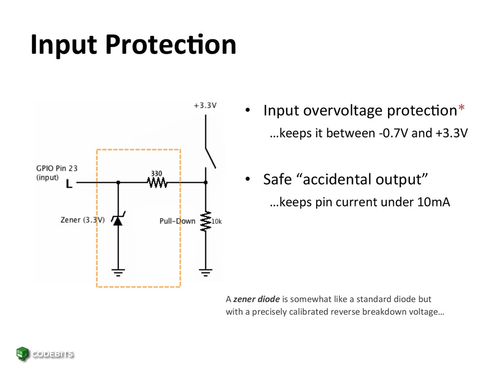
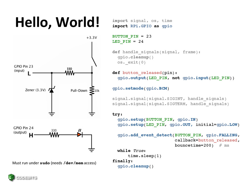
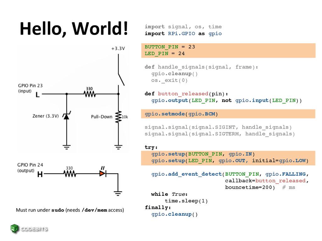
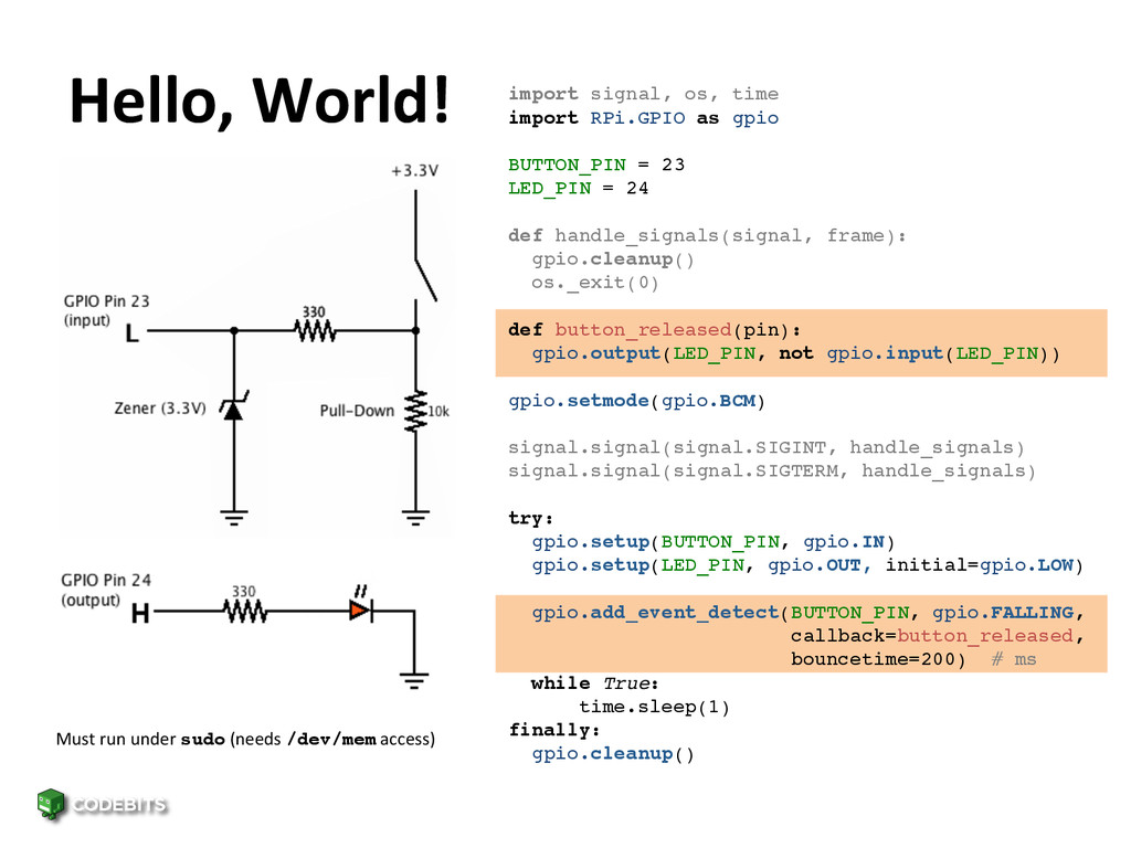
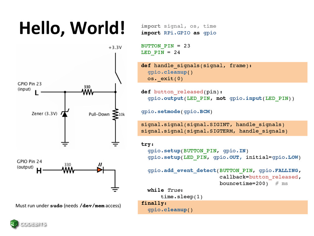
between -‐0.7V and +3.3V • Safe “accidental output” …keeps pin current under 10mA A zener diode is somewhat like a standard diode but with a precisely calibrated reverse breakdown voltage…
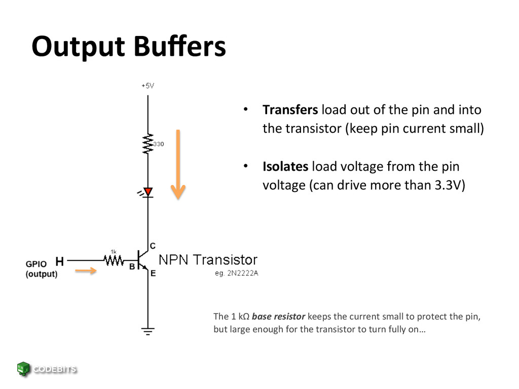
and into the transistor (keep pin current small) • Isolates load voltage from the pin voltage (can drive more than 3.3V) The 1 kΩ base resistor keeps the current small to protect the pin, but large enough for the transistor to turn fully on…
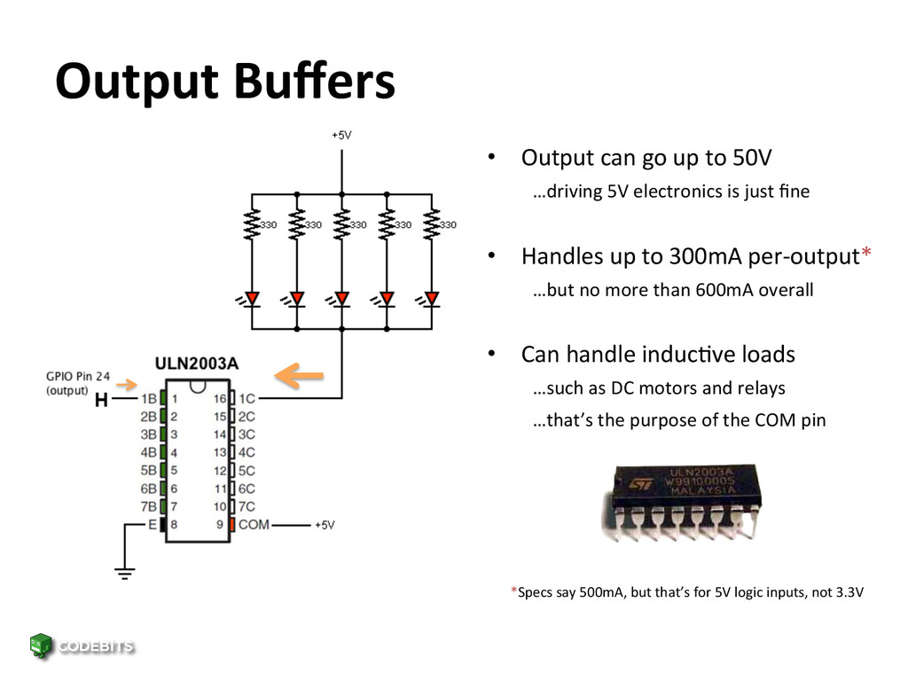
…driving 5V electronics is just fine • Handles up to 300mA per-‐output* …but no more than 600mA overall • Can handle inducFve loads …such as DC motors and relays …that’s the purpose of the COM pin *Specs say 500mA, but that’s for 5V logic inputs, not 3.3V !
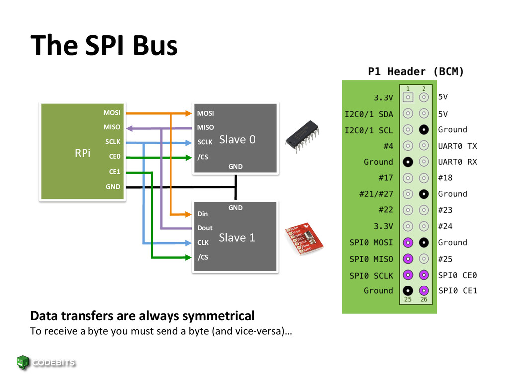
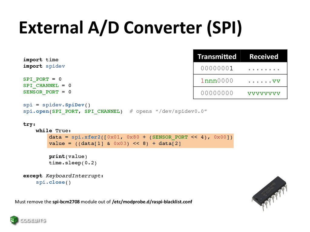
1 MOSI MISO SCLK CE0 CE1 MOSI MISO SCLK /CS Din Dout CLK /CS GND GND GND Data transfers are always symmetrical To receive a byte you must send a byte (and vice-‐versa)…
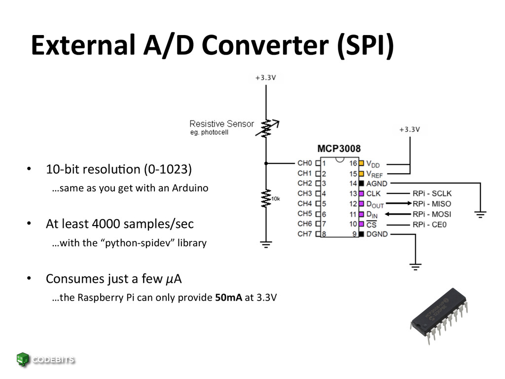
…same as you get with an Arduino • At least 4000 samples/sec …with the “python-‐spidev” library • Consumes just a few μA …the Raspberry Pi can only provide 50mA at 3.3V
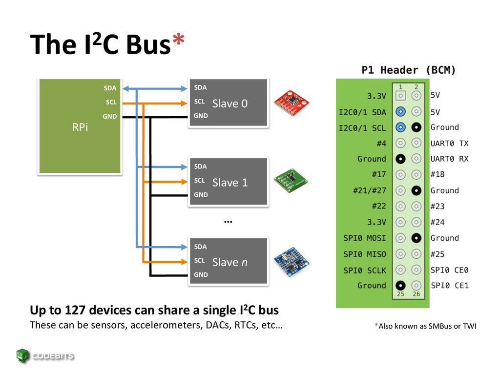
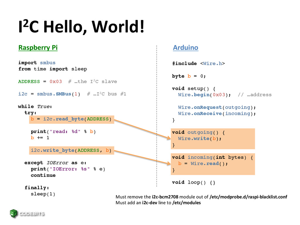
GND Slave 0 SDA SCL GND Slave 1 SDA SCL GND Slave n SDA SCL GND … Up to 127 devices can share a single I2C bus These can be sensors, accelerometers, DACs, RTCs, etc… *Also known as SMBus or TWI!
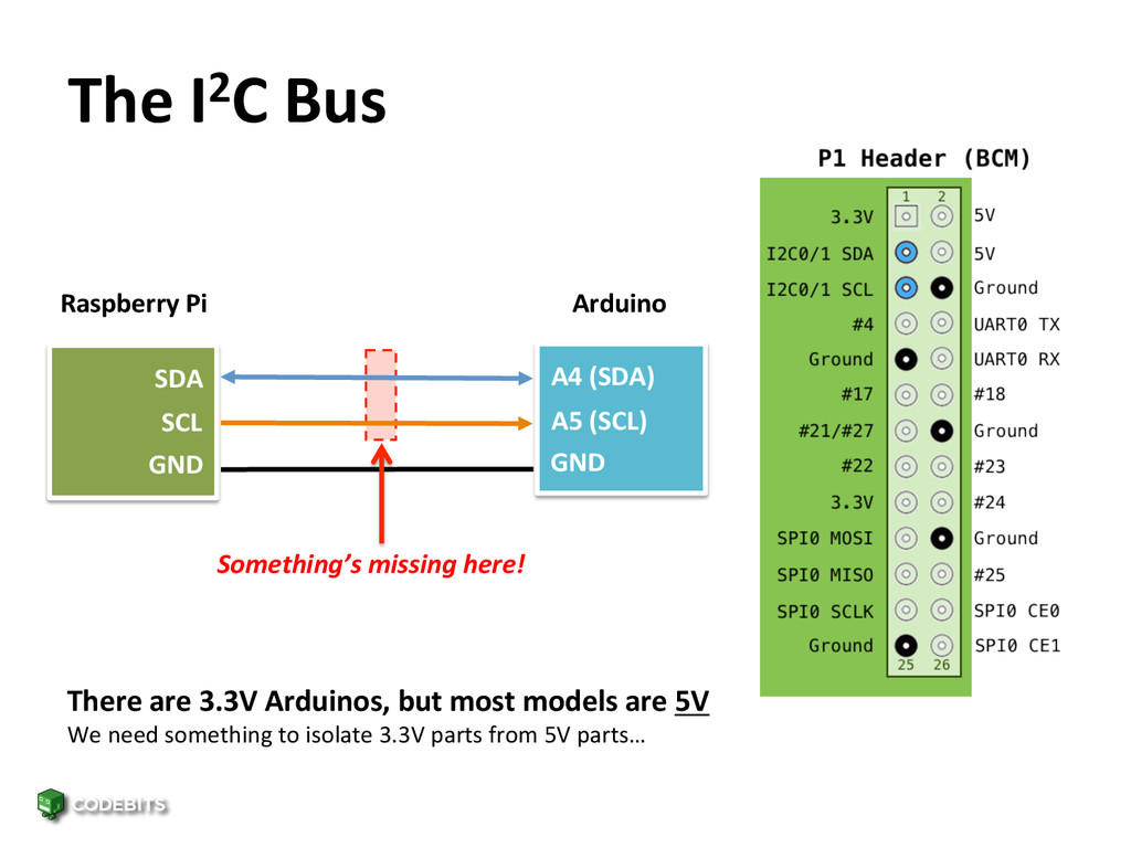
A5 (SCL) Something’s missing here! Arduino Raspberry Pi GND GND There are 3.3V Arduinos, but most models are 5V We need something to isolate 3.3V parts from 5V parts…
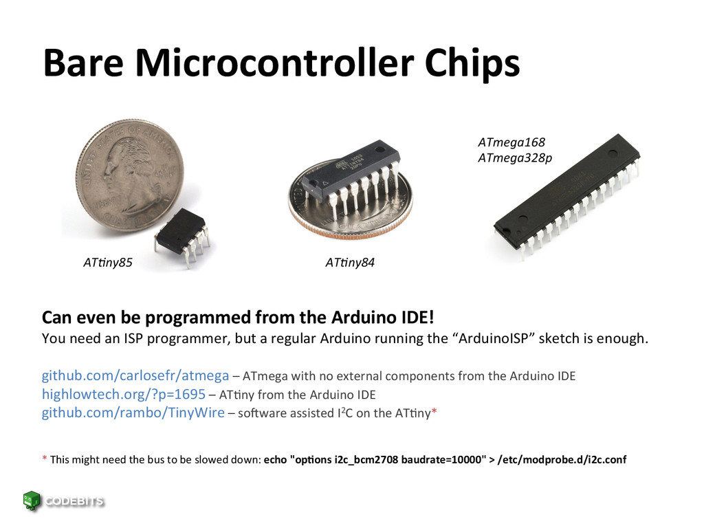
be programmed from the Arduino IDE! You need an ISP programmer, but a regular Arduino running the “ArduinoISP” sketch is enough. github.com/carlosefr/atmega – ATmega with no external components from the Arduino IDE highlowtech.org/?p=1695 – ATFny from the Arduino IDE github.com/rambo/TinyWire – so_ware assisted I2C on the ATFny* ATmega168 ATmega328p * This might need the bus to be slowed down: echo "op&ons i2c_bcm2708 baudrate=10000" > /etc/modprobe.d/i2c.conf
![Thanks for Listening! Carlos Rodrigues [email protected]](https://files.speakerdeck.com/presentations/d1c5ab00c9ae013177961a6d5d688b8e/slide_28.jpg)